


Composite ARF Mig29


 01-08-2019, 08:21 AM
#553
Martin, I am doing the build for the owner who acquired it pretty much in the state it is already in, so those were already in place when I got it. I suspect that was the case, and that may be why the extra ply is installed just behind the cylinder to add strength back to the rails for the turbine mounts.
01-09-2019, 01:32 AM
#556

A couple of recommendations, based on experience with my Mig, which I am working on now.
Stab. After the stab fluttered on its last flight, I have reinforced the tubes in the stab. with 1/8 carbon plates glued to the top and bottom of the tubes. These plates now capture the bolts which transmit torque to the stab.
After the flutter there is no sign of structural damage to the servo mount or the servo, JR6301 HV.
Servos. I have replaced the JR. With the Futaba HPS A700, superb servo, ultra powerful, tightest gears, perfect for the job( Despite an earlier suggestion, on another thread that these servos will only be used in a few specialist applications, the A 700 was RC. Japan,s top selling Futaba servo in the last half year ! )
During this work I discovered that some fuselage skin had seperated from the structure near the inboard ends of the lower tunnel, where the rear jet pipes plug in. This was fixed by gluing a 1/8 th glass board to the flange of the rear fuselage tunnels and this piece now extends down( or up) onto the fusekage structure and even onto the rear wing tube. It goes almost to the top of the center fuselage flange and is tge width of the flange. Vastly stronger.
Perhaps I could also add that I injected a considerable amount if Hysol into the area of the fin rods, to prevent the cracking I found earlier.This was done by drilling small holes alongside the rods allowing injection of the Hysol.
Seems to have worked, no more cracking and no effect from the flutter incident.
DG.
My fuel tanks are from Turbine Connection, long defunct. The company that is, not the tanks !
OK, the Futabas are in. Another tip. I did mount the Futabas with the screws iriginall used for the JR. I found they are a few thou. thinner than the screws supplied with the Futabas. Swapped over the screws and it further stiifened the servo mounting.
I also wedged the servos in place so any flutter force is unable to move the servo longitudinally. Every little helps to combat flutter !
Last edited by David Gladwin; 01-09-2019 at 07:00 AM.
01-09-2019, 06:44 AM
#557
David, I recall reading of your stab flutter and repair - did you by chance take any photos of that repair? I presume you actually cut the stabs open from the bottom to remove the tube and add your carbon plate, is that right?
The kit I have seems unusually light compared to the 50-55lbs I've been reading about - fully loaded before I stripped it I weighed it at 46.5lbs (21kg) - so I'm not afraid to add more reinforcement where needed. Plus I will be saving another 2+ lbs in the tail, as that weight was with older P120s and it will be getting a pair of Rabbits in their place.
The kit I have seems unusually light compared to the 50-55lbs I've been reading about - fully loaded before I stripped it I weighed it at 46.5lbs (21kg) - so I'm not afraid to add more reinforcement where needed. Plus I will be saving another 2+ lbs in the tail, as that weight was with older P120s and it will be getting a pair of Rabbits in their place.
01-09-2019, 06:56 AM
#558
Sorry no photos and now nothing to see ! No, I did not cut the tube, just removed the skin, both sides of tube, which was replaced by the plates.After sanding a slight flat on both sides of the tube the plate was Hysoled to it.
Slight surface refinish and paint touchch up and job done .
Ithink it worthwhile doing as it gives a much more secure torque transfer to the stabs.
D
Slight surface refinish and paint touchch up and job done .
Ithink it worthwhile doing as it gives a much more secure torque transfer to the stabs.
D
Last edited by David Gladwin; 01-09-2019 at 06:59 AM.
 01-09-2019, 08:57 PM
#560

Hi Chris,
the right stab pivot tube is at the wrong angle. I split mine, chiselled it out and glued in a realigned tube.
I also turned up aircraft grade Ali pivot rods which I tapped for the retaining bolts. On the lower surface I cut away the skin, glued in 3mm Ali plate, drilled through that and the pivot rods and tapped the pivot rods for the retaining bolts. I then covered the Ali plate and skin with a large bidirectional carbon cloth patch prior to refinishing.
Stab servo amounts were structurally tied to the pivot rod tubes (photos earlier in this thread). That I think is very important as there is a bit of flex in the structure when you load test the stabs functionally. My mods took a lot of slop out of the stab mechanism.
I made wooden formers to support the fin rods and I flooded the surrounds of the fin rods with hysol. The fuse in that area needs some stiffening to minimise flexing of the fins
01-10-2019, 01:53 AM
#562
Sorry no photos and now nothing to see ! No, I did not cut the tube, just removed the skin, both sides of tube, which was replaced by the plates.After sanding a slight flat on both sides of the tube the plate was Hysoled to it.
Slight surface refinish and paint touchch up and job done .
Ithink it worthwhile doing as it gives a much more secure torque transfer to the stabs.
D
Slight surface refinish and paint touchch up and job done .
Ithink it worthwhile doing as it gives a much more secure torque transfer to the stabs.
D
01-11-2019, 05:42 AM
#563
Been working on my Mig this week:
Strongly recommend that extra structure at the rear inboard end of center tunnels. Its adds considerable strength to a rather weak area.
Futaba A700 servos are in, tightly wedged, greatly increase stiffness and reduces play in stab.
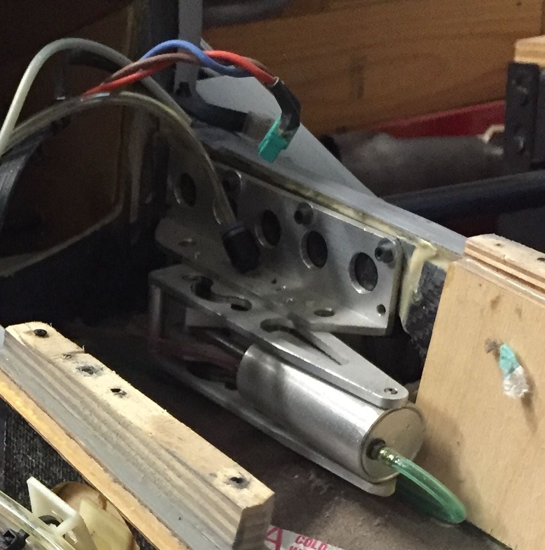
Great news: My downlocks were provided by servo actuated Festo valves, controlled by the Jetronics sequncer.
For initial testst, on the noseleg, I have disconnected that valve and installed a Festo pilot valve, as discussed in an earlier post. It works beautifully AND can shorten the retraction time as we no longer need the 1 second for the locking valves to open before retraction begins. Downlock is perfect, completely solid. 20 perfect cycles this morning, no leaks no problems, airworthy !
After taxi trials I will install these pilot valves on the main gear, but at the moment they seem perfect.
So after all these years I can start on the cockpit and some scale details !
David
Strongly recommend that extra structure at the rear inboard end of center tunnels. Its adds considerable strength to a rather weak area.
Futaba A700 servos are in, tightly wedged, greatly increase stiffness and reduces play in stab.
Great news: My downlocks were provided by servo actuated Festo valves, controlled by the Jetronics sequncer.
For initial testst, on the noseleg, I have disconnected that valve and installed a Festo pilot valve, as discussed in an earlier post. It works beautifully AND can shorten the retraction time as we no longer need the 1 second for the locking valves to open before retraction begins. Downlock is perfect, completely solid. 20 perfect cycles this morning, no leaks no problems, airworthy !
After taxi trials I will install these pilot valves on the main gear, but at the moment they seem perfect.
So after all these years I can start on the cockpit and some scale details !
David
Last edited by David Gladwin; 01-11-2019 at 05:50 AM.
01-11-2019, 11:58 AM
#564
Great to hear David. I�ve been running those festo pilot check valves for a few years on the Mig. One on each leg. Over 20 flights with no issues. I�m sure you�ve got it covered but the only thing is to make sure the hydraulic line between the pilot valve and the hydraulic ram is able to withstand high pressure, as with these valves all of the load is transferred to that line between ram and check valve. I had one blister during early taxi testing. On the nose gear I�ve got the pilot valve mounted at the top of the 45 deg ram with a brass tube between the two.
Cheers
Levi
Cheers
Levi
01-11-2019, 01:30 PM
#565
Thanks Levi. Indeed I have it covered as ALL plastic, flexible, lines are high pressure Festo tubing. No probs after a dozen flights
Grateful to Aussie Bart for the advice and Craig for the Futaba 700
servo.
Looking forward to detailing the jet now, cockpit etc !
BRG
David.
01-16-2019, 07:23 AM
#567
Well I think I might be on the right track with getting my gear aligned, waiting on my Robart wheels now to confirm fitment and solidify the mounts. Once they're in I'll finalize the air systems (see next item as well), then I will start looking at the stab alignment and strength.
Question for the guys flying these, how are you utilizing the speed brakes? I was surprised to learn the full scale MiG-29 does not use them for landing at all, in fact I think they're disabled with gear down entirely. So for our models they seem like a neat feature for slow fly-bys, but otherwise no real benefit or need from a flight performance standpoint, is that about right? Especially a bummer that I can't enable my LEF, not sure it's worth plumbing the speed brakes either.
Also just because I'm curious, how do you guys use the intake covers/upper vents? Just on a switch/slider that you activate after landing for a cool looking taxi back to the pits? I imagine I'd build in a mix to open the intakes when throttle advances above half in case I ever forget otherwise, but wondering what others had done.
01-18-2019, 10:24 AM
#568
More work on the Mig today:
Following Levi’s experience I have fitted the Festo pilot valves to the main legs. Downlock is solid, wish I had know about these years ago. Thanks Levi and Shane!
The Futaba A700 servos are in. The control circuit has virtually zero slop and the bolts are captured in the plates I fitted to the tubes very securely. The free movement of the stabs. Is now better but still too much, almost 1/4 inch at the stab. TE.
The only source of this slop HAD to be in the holes for the bolts in the stab. Pivot and so it proved.
The bolts could “rock” just a degree or so as the holes were just a few thou. too large. Even a tiny amount of free play in these bolt holes are magnified many times at the stab. TE. That oversize has been , hopefully, eliminated by putting a wipe of Hysol inside the holes. When dry I will retap. aiming for a totall slop free fit which should lead to minimal slop in the stab.
Cockpit detail well on the way, but need to spend some time cleaning up the mouldings but the abs sidewalls and floor mouldings fit quite well.
Hope this helps you guys.
As for speedbrakes, mine are locked (as are intake doors, open) shut at the moment. The real Mig probably does not use them as the lower blade might contact the runway on landing. The Hawk and Hunter similarly dont use them for landing, loud scraping noises otherwise !
David.
Last edited by David Gladwin; 01-18-2019 at 10:30 AM.
01-19-2019, 09:44 AM
#569
Well, it worked. After the Hysol set, I retapped the shaft holes to make the bolts a perfect fit. They also now engage perfectly in the carbon plates glued to the Stab. Tubes. Result : ZERO slop !
Last edited by David Gladwin; 01-19-2019 at 09:50 AM.
01-21-2019, 01:52 AM
#571
Sorry, there�s now nothing to see. Getting zero slop was all about closing up tolerances on the holes for the bolts in the shaft and the carbon plates glued to both sides of the stab. tubes. as I described !
Even 1 degree of play in the bolt holes results in a free movement, slop, of the stab. te of 5 mm, 1/ 5 th of an inch. as the TE of the stab. Is 12 inches aft of the pivot, so a secure, precise fitting of the bolts both in the shafts and stabs. yields great benefit.
David.
Even 1 degree of play in the bolt holes results in a free movement, slop, of the stab. te of 5 mm, 1/ 5 th of an inch. as the TE of the stab. Is 12 inches aft of the pivot, so a secure, precise fitting of the bolts both in the shafts and stabs. yields great benefit.
David.
Last edited by David Gladwin; 01-21-2019 at 01:59 AM.
01-21-2019, 05:23 AM
#572
Hi David,
I did did the same on my P47 but also mixed some milled glass fibre in as well for extra strength... it worked well. I think I will do the same with my stab bolt holes also. With a tiny bit of play I expect the trim of the model might be different every time I take her out and put the stabs on. Massive cantilever on the mig stabs.
I did did the same on my P47 but also mixed some milled glass fibre in as well for extra strength... it worked well. I think I will do the same with my stab bolt holes also. With a tiny bit of play I expect the trim of the model might be different every time I take her out and put the stabs on. Massive cantilever on the mig stabs.
02-11-2019, 09:03 AM
#573
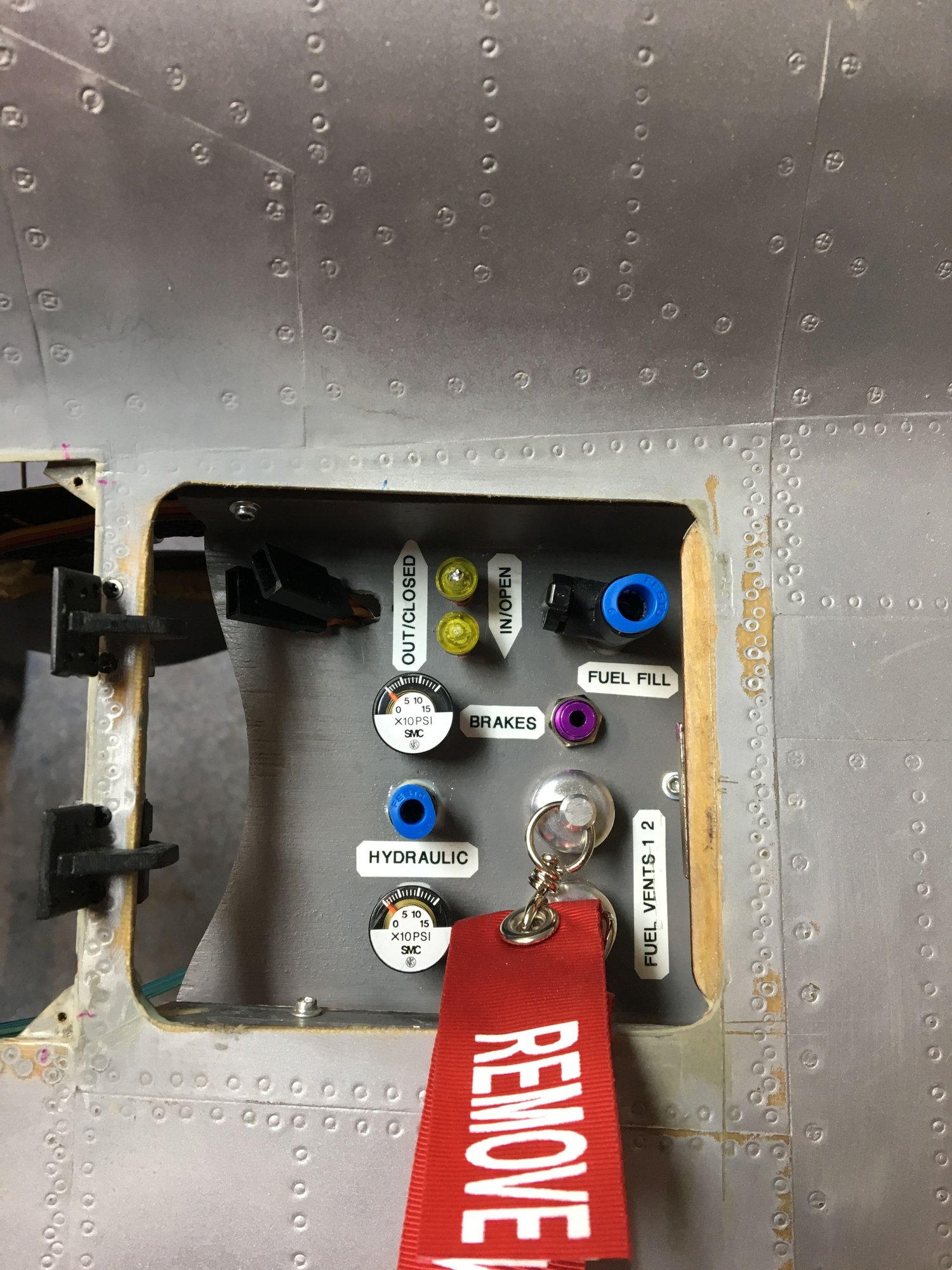
Hey Nick, what method did you go with to latch that access panel? I ended up opening up one side and have it hinged in the front just like yours with a small magnet at the back - seems to hold okay, plus the airflow will not try to open it anyway so should be fine.
I was able to fit my fuel shutoffs and GSUs inside of that hatch, air and fueling access along with charging will all be handled via the nose cone. Using all LiFe batteries so I can charge them in the airplane, so the leads will be accessible even if the batteries aren't. I expect all batteries to be somewhere in the vicinity of the nose, but waiting for my wheels still to set up the Xicoy balancer and load everything up where I expect it all to be. I'll be shooting for CG 20mm forward of the spar like Levi has shown in pics.
In the meantime I pulled the stab servos only to find that the screws were barely finger tight and the 1/8" light ply was mushy and split, so I'm backing it with 1/4" ply blocks and will run in some longer #6 wood screws. Once those blocks are finished I also have a pair of Futaba A700s ready to go in when my SWB arms for them show up. Would it kill Futaba to include a decent aluminum horn or two with a $250 servo?
The good news is I can't detect any angle problems with the stabs, so they were either ok on this kit or a previous owner/builder already corrected them.
Last edited by Auburn02; 02-11-2019 at 09:05 AM.
02-11-2019, 08:59 PM
#574
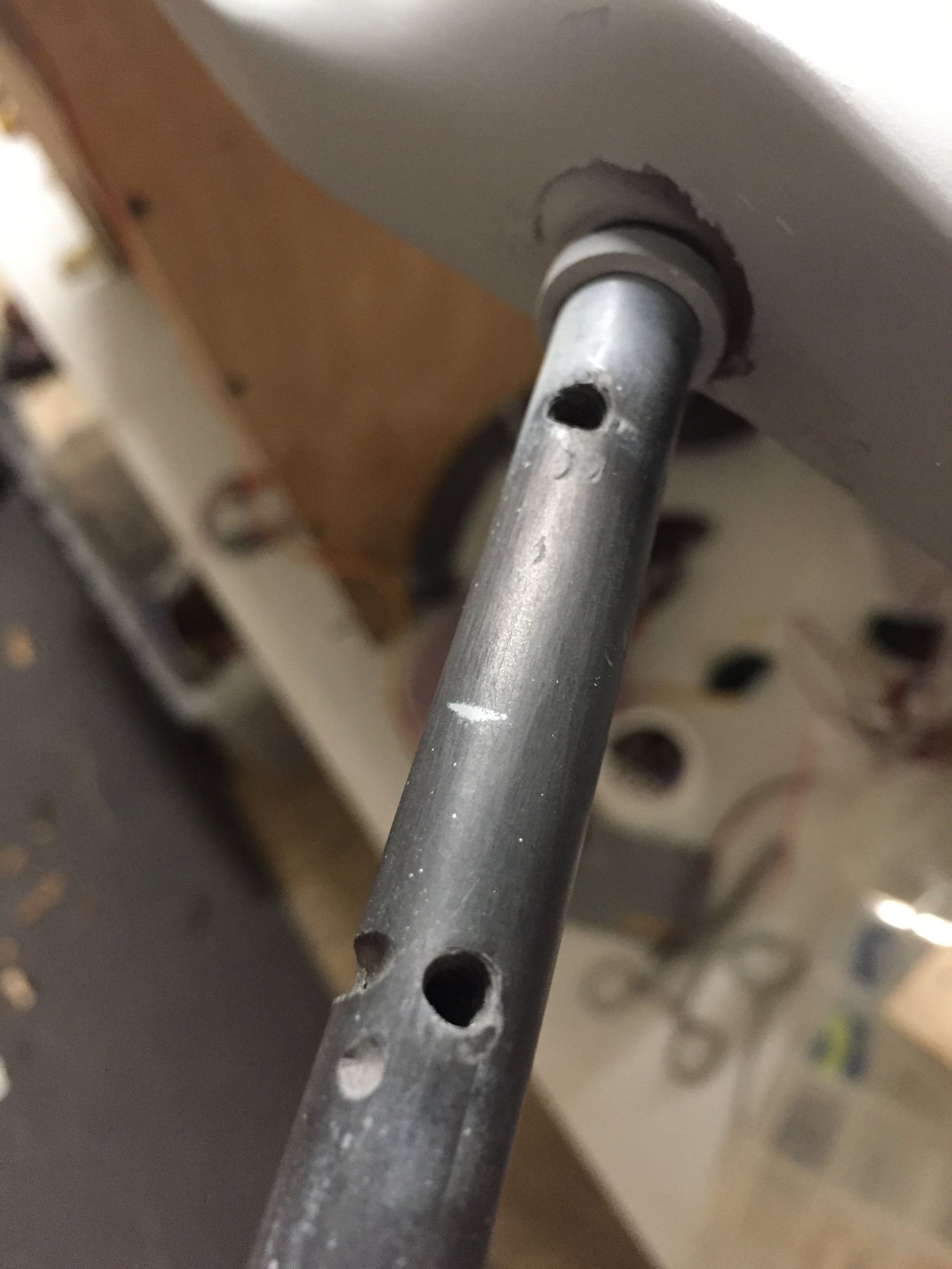
Alright, need some input from you other builders, or anyone with expertise about carbon fiber and its properties. First, the stab rods - for starters the holes for the stabs themselves are all kinds of off kilter, looks like there was a misfired drilling that went through the edge of the rod even. Also further out towards the end of each rod are two more unidentified holes. Should I be worried about the integrity of these?
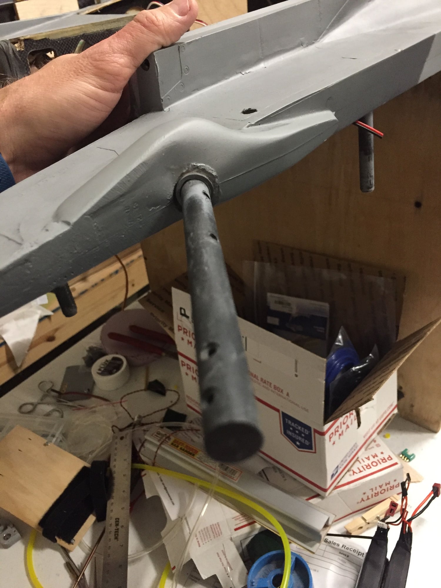
Next, with the wing spars are only the fronts bolted in place? And would you be concerned about the bolts being off center like these? This would be easy enough I think to drill new holes about 1/2” closer to the fuse and get them centered, but a) I don’t know where or if there are blocks in the wings to tighten down bolts and b) these are really more like pins just to keep the wings from sliding out so maybe it’s fine as is. Thoughts?
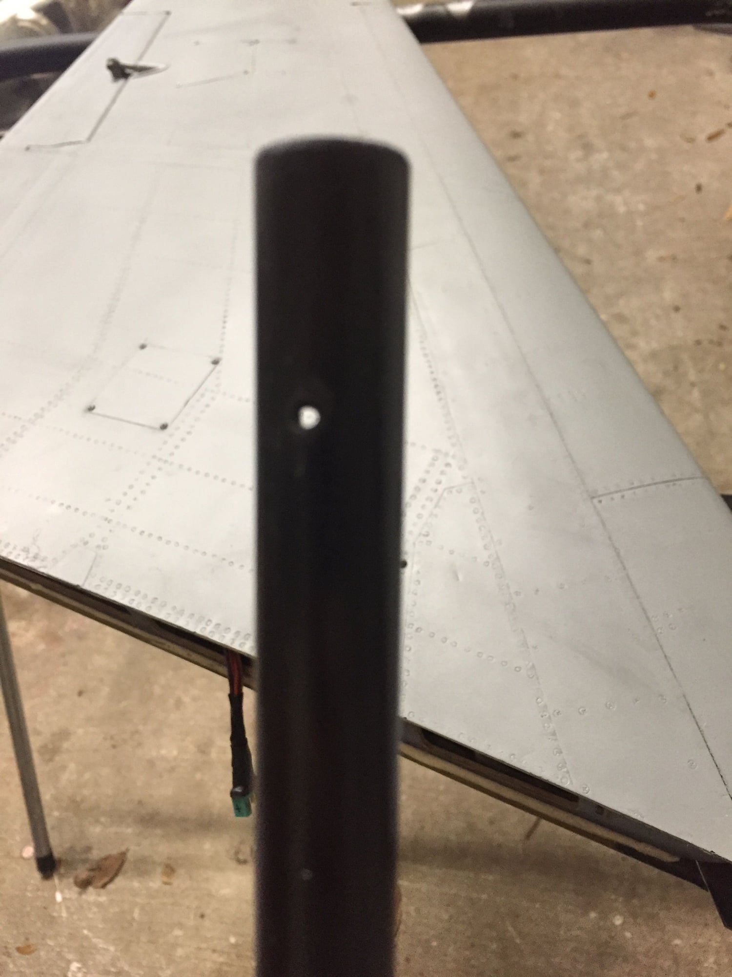

Next, with the wing spars are only the fronts bolted in place? And would you be concerned about the bolts being off center like these? This would be easy enough I think to drill new holes about 1/2” closer to the fuse and get them centered, but a) I don’t know where or if there are blocks in the wings to tighten down bolts and b) these are really more like pins just to keep the wings from sliding out so maybe it’s fine as is. Thoughts?
Last edited by Auburn02; 02-11-2019 at 09:01 PM.
02-11-2019, 09:55 PM
#575
Uh! Replace the elevator rods! (Because of the inner possible crack point)
Wing with no centre bore is no big problem, because it only holds the wing to the fuse.
regards Martin
Wing with no centre bore is no big problem, because it only holds the wing to the fuse.
regards Martin