


Composite ARF Mig29
 02-12-2019, 01:35 AM
#576

I would certainly replace the stab. Shafts as the inboard holes you show are near the bending point. Failure of these pultruded rods is unlikely in normal use, but in a flutter sutuation as I encountered, who knows ?
Replacement would be my remedy.
I changed the wing retention method. There is a blind nut mounted inside wing root rib, with a bolt inserted from the wheel well. One in each wing. It works and is easier than fiddling around finding the holes in the wing rods !
My Mig is airworthy, just waiting for some warmer weather to do some paint refinishing etc. The scale cockpit is done, just needs painting
David.
 02-12-2019, 06:19 AM
#577

Thanks fellas, that's kind of what I was thinking too but wasn't sure if I was overthinking it.
David, can you clarify what you mean about they are near the bending point?
How far out on the stab are others mounted? I'll search this thread for any more pics of other setups.
Now, where to get 12mm pultruded CF rod and quick...
How far out on the stab are others mounted? I'll search this thread for any more pics of other setups.
Now, where to get 12mm pultruded CF rod and quick...
Last edited by Auburn02; 02-12-2019 at 06:30 AM.
02-12-2019, 09:27 AM
#578
Well no luck on any photos of stab undersides in this thread. If anyone can share a pic or two of their stab/tube setup to show how far out the bolts are installed, that'd be great. Likewise, any more info on the wing mounting would be appreciated - i.e. did you use a blind nut in the root rib like David, one bolt through the forward spar a bolt through each spar, what size bolts, etc.
Wish I had a dang manual for this bird.
Wish I had a dang manual for this bird.
02-12-2019, 09:30 AM
#579


the manual wasnt much help when it came to any of that stuff. I glued and bolted the stab spars into the stab and machined control horns that fit over the inboard end of the shaft to connect to the ball link and used one large servo. The suggested method of connecting servos in the manual is one of the most ghetto methods I have ever seen.
 02-12-2019, 09:34 AM
#580
the manual wasnt much help when it came to any of that stuff. I glued and bolted the stab spars into the stab and machined control horns that fit over the inboard end of the shaft to connect to the ball link and used one large servo. The suggested method of connecting servos in the manual is one of the most ghetto methods I have ever seen.
Thanks Jeremy!
02-12-2019, 12:50 PM
#581
You know, I had thought about just gluing them into the stabs. I'm not sure what the original connection method was for connecting servos, but this plane does have a machined horn that slips over the inboard end of the pivot rod and secured by a bolt, ball link connecting that horn to a single servo. I really don't plan to remove the stabs for transport, so having to open up the nacelles to do it on the rare occasion I need to pull them wouldn't be the end of the world. I think you just helped make that decision for me. Still need to order some new undrilled rods though.
Thanks Jeremy!
Thanks Jeremy!
02-12-2019, 12:52 PM
#582
Wow, that does sound awful.
I went back to your build thread and the one I'm finishing now has a very similar setup to what you made. I'll get some pics up as I work through this one. Do you recall your wing attachment method, anything crazy there?
I went back to your build thread and the one I'm finishing now has a very similar setup to what you made. I'll get some pics up as I work through this one. Do you recall your wing attachment method, anything crazy there?
02-12-2019, 12:57 PM
#583
There is a picture in this post of the control horns I made up for the stabs. There were 2 aluminum horns welded to an aluminum spacer between them that spacer was drilled and tapped and the carbon shaft drilled and tapped so when the bolt went through it locked everything into place. The horn was positioned up against the stab spar socket to keep the stabs from moving in and out as well.
http://www.rcuniverse.com/forum/10715312-post89.html
http://www.rcuniverse.com/forum/10715312-post89.html
02-13-2019, 01:48 AM
#585
02-13-2019, 01:58 AM
#586
Thanks fellas, that's kind of what I was thinking too but wasn't sure if I was overthinking it.
David, can you clarify what you mean about they are near the bending point?
How far out on the stab are others mounted? I'll search this thread for any more pics of other setups.
Now, where to get 12mm pultruded CF rod and quick...
David, can you clarify what you mean about they are near the bending point?
How far out on the stab are others mounted? I'll search this thread for any more pics of other setups.
Now, where to get 12mm pultruded CF rod and quick...
Probability is the rod wont actually bend ( pultruded CF is very resistant to bending) but could merely snap.
Unlikely but.......
D.
02-13-2019, 05:24 AM
#587
Join Date: May 2002
Location: Washington,
MI
Posts: 221
Likes: 0
Received 0 Likes
on
0 Posts
Thanks David for the quick response.
I�m still waiting for my pump and valve from HP Tech but i have another question about the hydraulic system. The old system used a controller to operate the pump. Does the HP Tech pump us a controller as well. If so is it the one that came with the kit. Mine is the original unit
thanks
John
I�m still waiting for my pump and valve from HP Tech but i have another question about the hydraulic system. The old system used a controller to operate the pump. Does the HP Tech pump us a controller as well. If so is it the one that came with the kit. Mine is the original unit
thanks
John
02-13-2019, 05:37 AM
#588
My HP pump came with an electronic controller with a small pressure sensor vessel, which has an air precharge of max 10 bar.
I believe the new units are all integrated, its a complete unit and uses a brushless motor. I have had one on order for months.
I have been working on my Mig this morning. The Festo valves have held the gear totally solid with the model stood on the bench, and the air precharge , filled before Christmas is still instantly producing 10 bar as soon as it is switched on !
David.
Last edited by David Gladwin; 02-13-2019 at 05:40 AM.
02-13-2019, 06:25 AM
#589
The shaft is supprted in the stab by the tube. Inside the fuse it is also supported by another tube. At the junctioin of the tubes is where the stress from vertical flexing, /loading, of the stab. Is concentrated. As your shafts have holes drilled near here they have weakened it where it needs to be strongest.
Probability is the rod wont actually bend ( pultruded CF is very resistant to bending) but could merely snap.
Unlikely but.......
D.
02-14-2019, 06:35 AM
#591
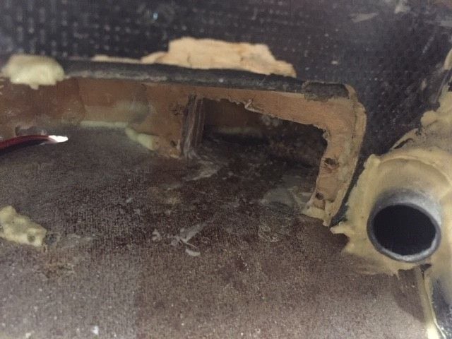
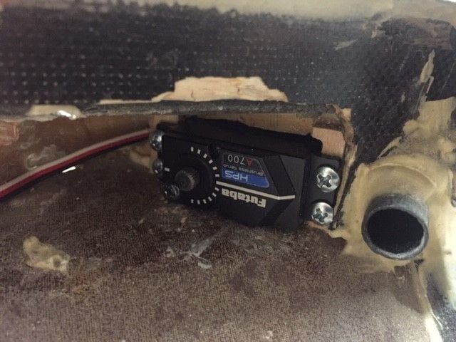
When I pulled the stab servos, they were mounted into this 1/8" layer of ply that was quite gnarled up and appears to have had the screws run in and out of it a couple hundred times as there was almost no bite left. First I added some 1/4" ply blocks to the backside of that 1/8" ply:
After that I realized that those original servos were pretty well bottomed out against the fuselage side. The new A700s were a hair taller plus I don't use the rubber grommets as the old servos had, so these will sit deeper in the mounts. Had to add an additional 1/8" ply to the front of the mounts, then mounted with #6 x 1/2" screws. The fuselage will fail around the mounts before the mounts fail.
Mocked up with the stab rod horn to verify alignment - new rods are on order from ACP Composites.
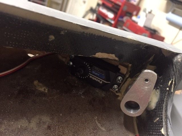
02-28-2019, 06:56 AM
#592
the manual wasnt much help when it came to any of that stuff. I glued and bolted the stab spars into the stab and machined control horns that fit over the inboard end of the shaft to connect to the ball link and used one large servo. The suggested method of connecting servos in the manual is one of the most ghetto methods I have ever seen.
 10-26-2019, 11:22 AM
#594
My Feedback: (44)

Join Date: Sep 2004
Location: Wilmette,
IL
Posts: 439
Likes: 0
Received 0 Likes
on
0 Posts
Finally we Jim Hiller and I flew the Mig 29 I was scared in the beginning but after I took over it seems like it flies like a trainer very stable aircraft I�m still having couple issues with the hydraulic system but I will try to fix it here�s a link.
10-27-2019, 03:38 PM
#598
My Feedback: (44)
Join Date: Sep 2004
Location: Wilmette,
IL
Posts: 439
Likes: 0
Received 0 Likes
on
0 Posts
Thank you Craig,
it�s the left leg it does not wanna retract as quick as that ride one so I incorporated a spring between the clevis and the cylinder to give a little bit more boost but it still does not go up in flight. The only way that it goes up,is by keeping it in an alpha position and then while I drop it down with a nose I retract the gear and that sometimes it works but I also believe that the plastic tubing 4 mm that I�m using is too soft and maybe I�m losing some pressure I run the system at 120 psi. What do you think the problem is?
it�s the left leg it does not wanna retract as quick as that ride one so I incorporated a spring between the clevis and the cylinder to give a little bit more boost but it still does not go up in flight. The only way that it goes up,is by keeping it in an alpha position and then while I drop it down with a nose I retract the gear and that sometimes it works but I also believe that the plastic tubing 4 mm that I�m using is too soft and maybe I�m losing some pressure I run the system at 120 psi. What do you think the problem is?
10-27-2019, 04:01 PM
#599

The geometry at the end of the retraction is unfavourable so you really need to run max Psi on the Hausl system (I assume you are running that system). I think it is rated to operate at 10 Bar. I think Levi said he relies on the doors to give the wheels a last little shove on his. I was thinking about using an auxiliary air ram in some way to assist with the last bit of the retraction cycle if necessary.
The only other solution would be to use a larger bore main gear cylinder for more force but space may preclude that due to the location of the rear wing spar. If only we could run 3000 Psi!
What did you use on your nose gear? Levi and I have 2 cylinders, one in the scale location and one at the top of the nose gear yolk as per the later version of the gear from CARF.
10-27-2019, 07:19 PM
#600
My Feedback: (44)
Join Date: Sep 2004
Location: Wilmette,
IL
Posts: 439
Likes: 0
Received 0 Likes
on
0 Posts
I also use the two cylinders for the nose gear from Hauls I got that fixed but the only one that I have a problem with is on the left main gear I think I will try a pull spring just to give her a little bit of a boost thank you I will see how it will do and I will let you know. At this moment I have stored it way the weather changed we will have snow Thursday the winter season is coming soon