


1/7th F-14D Scratch build thread *building started*
 09-19-2014, 11:58 AM
#1476

This printer is pretty open source. It uses and Arduino for the control board and everything is pretty easily changed/upgraded due to that. Things i'm planning to do to it are really just to make it
1. More accurate
2. Faster
3. Taller prints
Alot of the tweaks I have already done, but the best was buying a GOOD 3D printing software. The difference in print quality between the free open source and the $140 program was night and day difference (the $140 program is faster with higher quality to!).
The biggest thing i have noticed as of lately is that at the top of the print area on tall parts the print quality suffers. The reason for this is they use a regular 5/16-18 threaded rod to control the Z axis (height) and these wobble due to being bent. Since there is only 1 Z smooth rod for the system to travel up on the, the threaded rods allow the extruder to move ever so slightly. To fix this, i'm going to convert to Dual z smooth rods (doubling the current amount) and replace the threaded rods with a lead screw (i would like to use a ball screw, but at $180/each its not worth it). The next big mod will be getting rid of the stepper motor for the filament drive from the moving gantry and running it externally to eliminate weight and allow higher speeds. about $300-400 in upgrades all together on top of the $1200-1300 i've already spent on the printer.. but i'm still getting awesome prints for an FDM machine considering its less than half the price of a printer with a similar build volume.
 09-20-2014, 03:24 PM
#1477
After about a 80% redesign of the main landing gear, im beginning to fine tune the design to minimize cost. Here is the 3D printed main landing gear strut mount. This will be machined from a solid chunk of aluminum (no bolt on parts other than the cylinder mount) with press fit bronze bushings for the rotation pins. I am designing this gear to be absolutely bullet proof as the Complexity of the model is already large enough, i dont want to have to deal with sloppy landing gear that only works 1/2 the time.
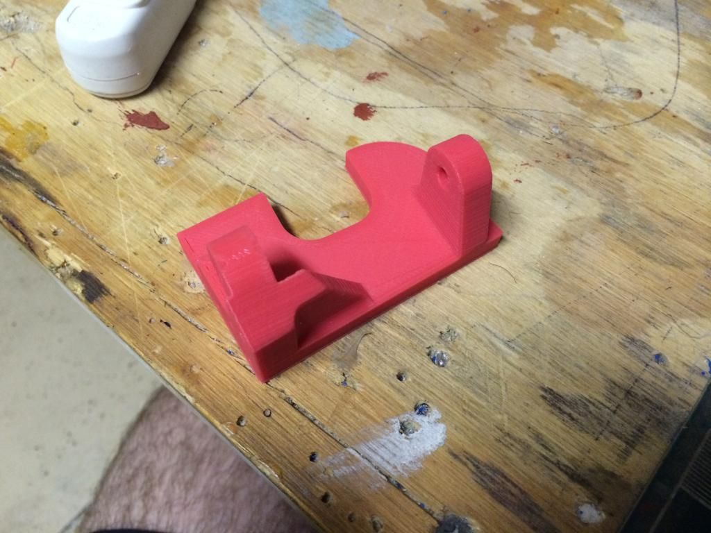


 and it is big !!
 09-21-2014, 03:18 PM
#1481
The main design for the main landing gear is done and all but two parts have been printed in their final form. All i have left to do from this point is mirror the parts for the left side and draw up all the steel hinge pins and either source air cylinder for the retraction and down lock, or design and draw my own.
Here's some photos:
Here's some photos:


 10-01-2014, 06:22 PM
#1485
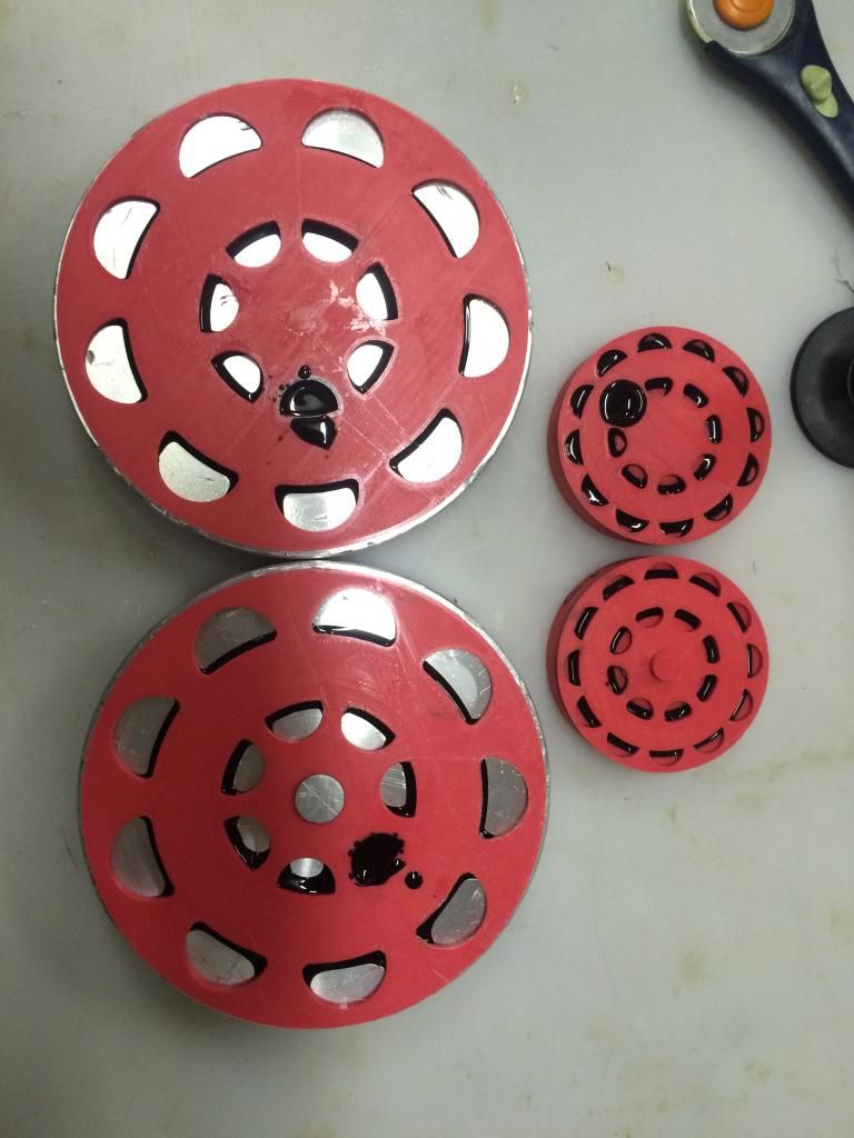
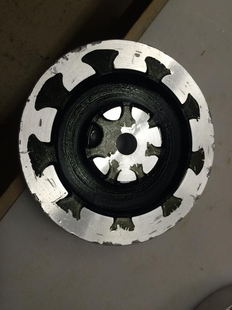
I poured the first prototype tiresa today. The main tires are utilizing a machined aluminum tire mold with a 3D printed cavity plug. The plug is used to decrease material useage and reduce weight. The tire has a slightly thicker area newr the tread and thinner walls in the side. My hope is the hollow nature of the tire will allow a scale squish to the tire but the hardness of the rubber will allow it to spring back to shape.
The nose tire is using a 3D printed mold and cavity tool. This is more of a test to see what kind of quality i can get out of the tire with a $6 mold compared to a $500 mold.
Molds and cavities assembled and material poured:
main tire with the cavity plug removed prior to clamping the two halves together:
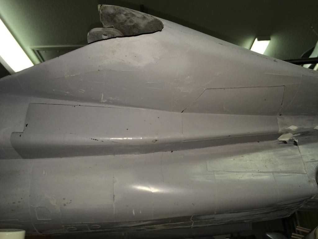
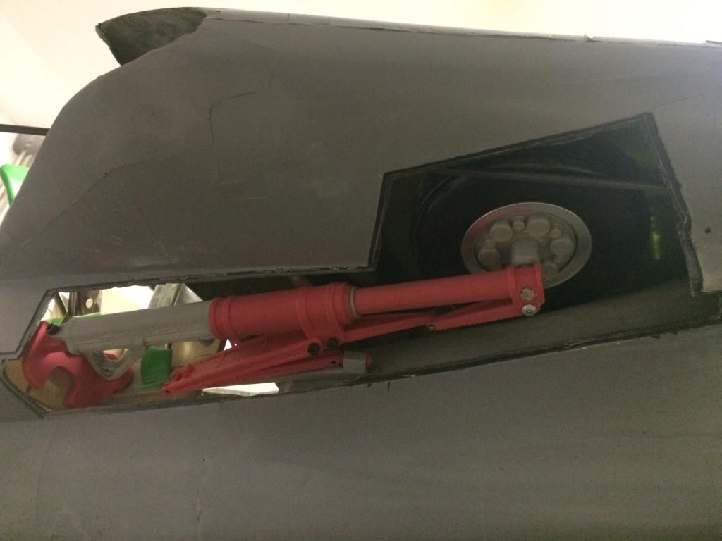
i also trimmed the right gear door molding to fit so i have it to help get the main gear fit properly. That is nearly done, im just making some final adjustments to get a bit more clearance between the strut and the doors.
The nose tire is using a 3D printed mold and cavity tool. This is more of a test to see what kind of quality i can get out of the tire with a $6 mold compared to a $500 mold.
Molds and cavities assembled and material poured:

main tire with the cavity plug removed prior to clamping the two halves together:

i also trimmed the right gear door molding to fit so i have it to help get the main gear fit properly. That is nearly done, im just making some final adjustments to get a bit more clearance between the strut and the doors.

 10-02-2014, 01:07 AM
#1487
 10-02-2014, 08:21 AM
#1488
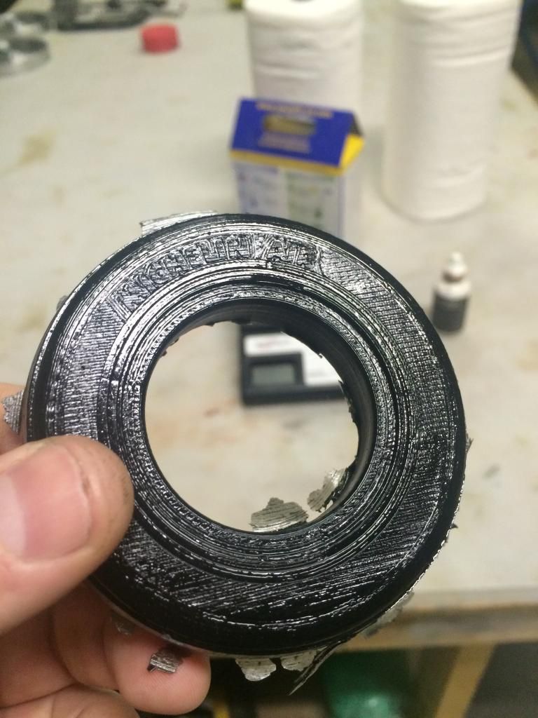
Here is the main gear tire. I waited a little to long (about 5 minutes) to pull the cores and join the molds so it didnt join together 100% around the seam. I figured this would happen, but the test was a success with the cavity core mold. Ill do the second one here in a bit.
the nose gear tire printed mold produced a pretty decent tire. Most of the layers from the printer are visible, but i believe it i use a smaller nozzle and thinner layer height, i can produce reasonable finished tires. This is encouraging as it will allow me to do alot of one off designs for wheels and tires without having to invest in expensive aluminum molds.
This photo the tire still has the mold release in it which makes it look much worse than it does in person.


 10-02-2014, 01:34 PM
#1490
Lol Jeremy. Im ready for this build to be done as well, unfortunately it looks like the first fuse is going to resort to becoming a mockup fuse only. Im not happy with the quality of the layup (im embarassed really) the internal structure needs serious refinement now that i have functional gear mockups and the thing is just flat out Heavy.
That said, it has proven to be exactly what i wanted the first one to be, A great learning tool. The second and first flying prototype fuselage should be around 6-8lbs lighter and one I will actually take to an event to show off.
So currently i have two projects slated for completion before this, one of those is 80% complete.. The other is fully designed and just waiting on the previous one to get done with composite layups so i can free up my big table. This second project should be completed by this time next year, which is when 100% of my attention will be devoted to the F14... This thing just needs to get Done!
10-04-2014, 10:09 AM
#1492
Well...
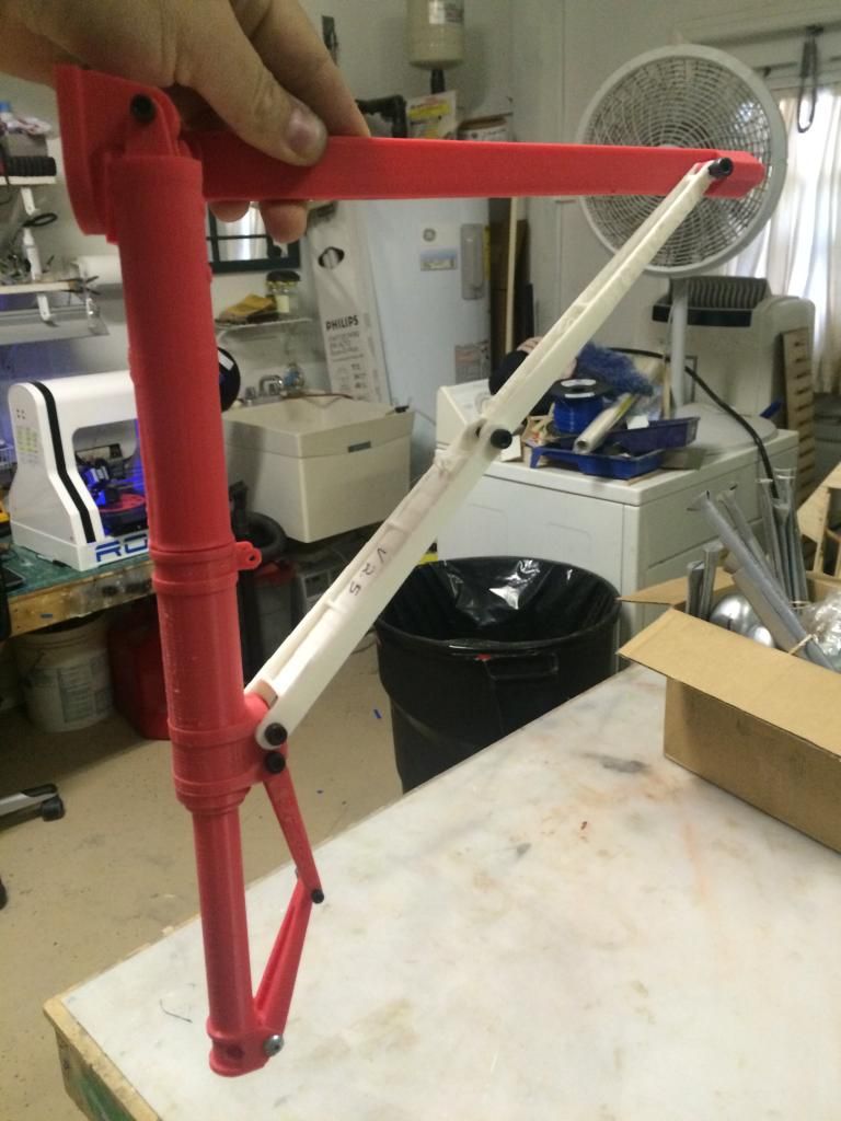
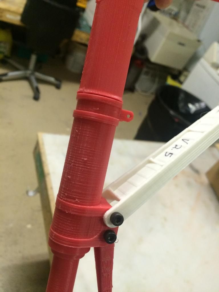
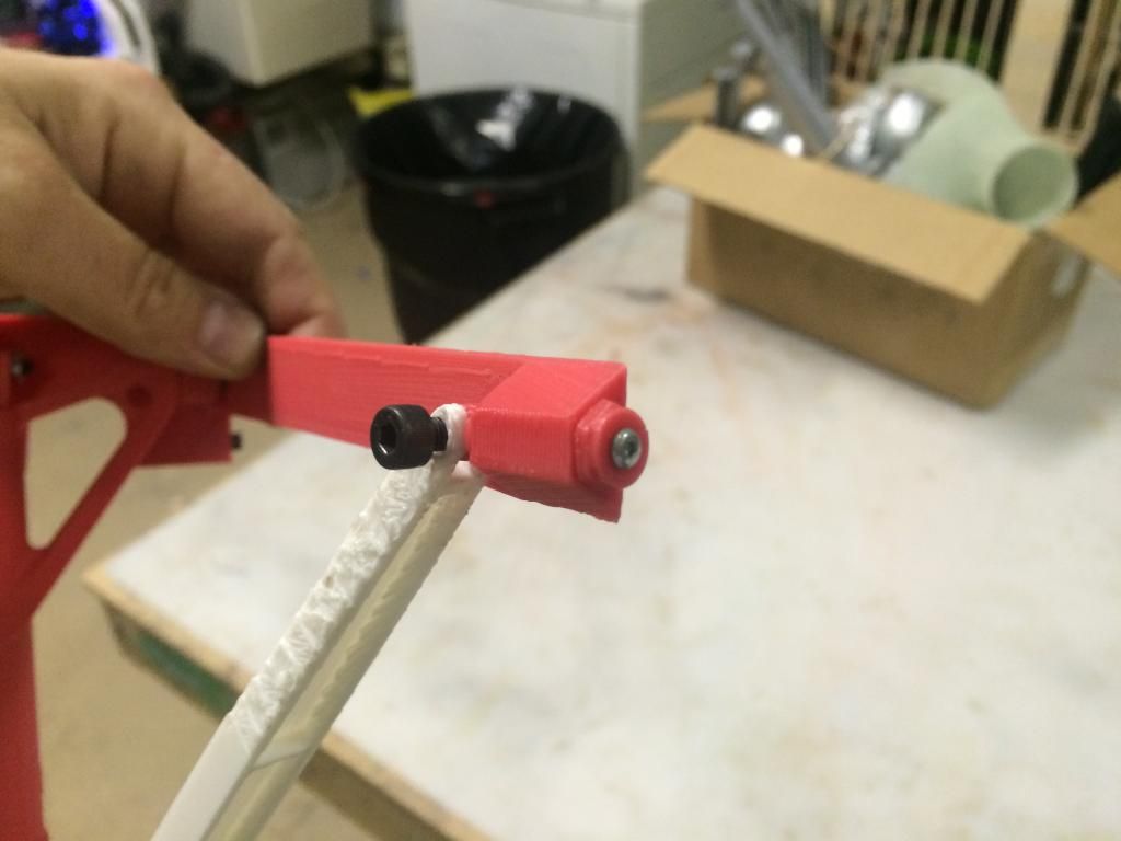
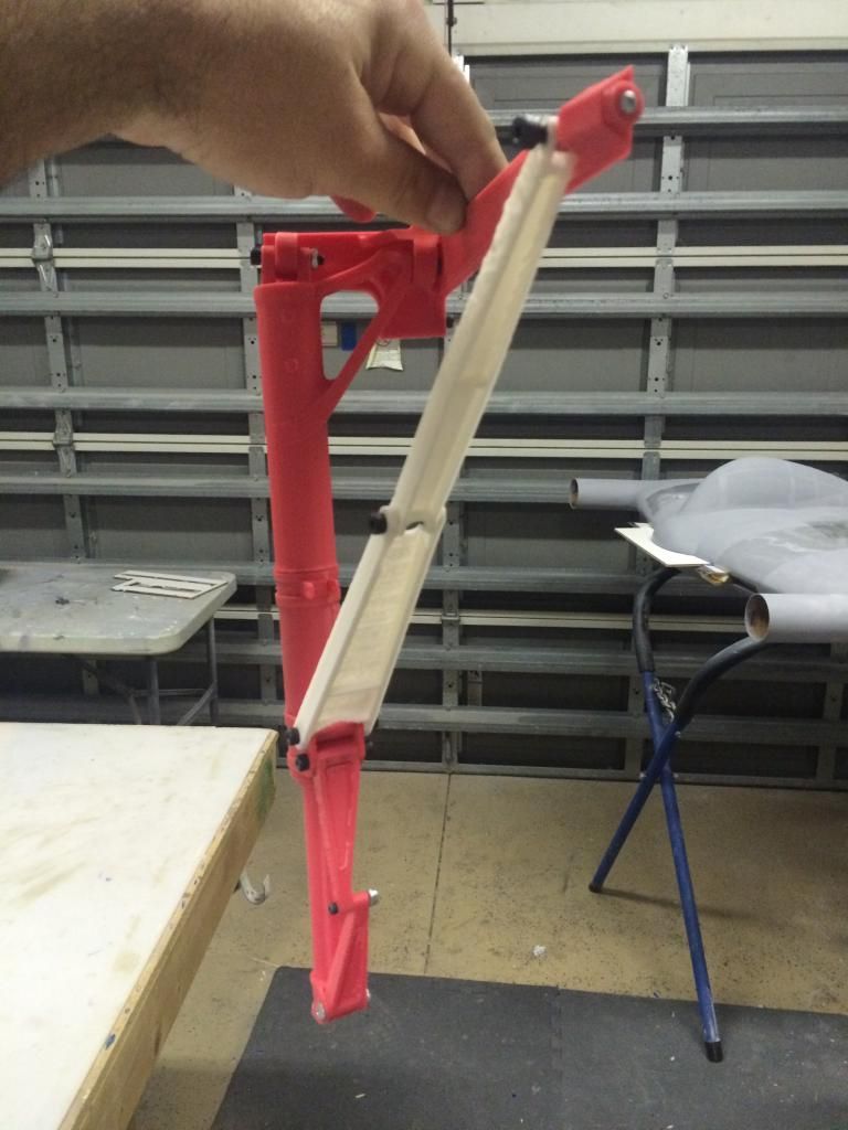
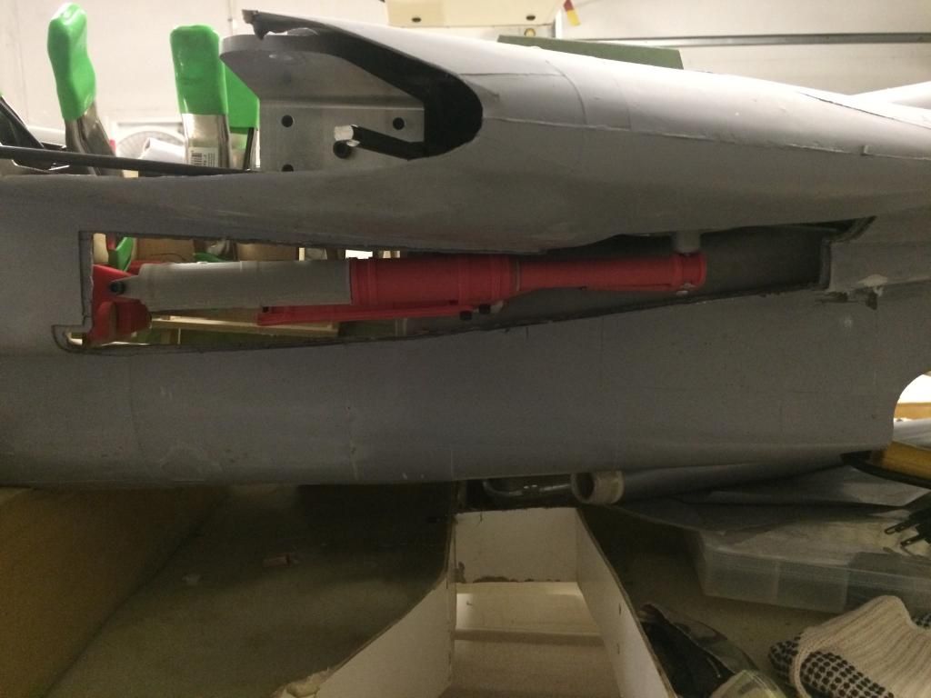
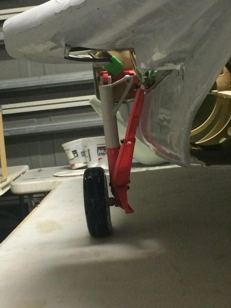
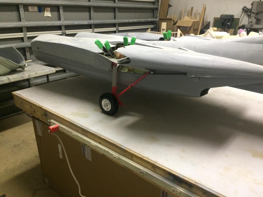
After Seven revisions to the version two gear to get the strut inside of the gear wells Just perfect and with the pivot locations as close to perfection as possible, the main landin gear strut design and geometry is finally done. All that is left to do is modify the latest revision of parts to eliminate some mill and lathe time and the actual mechanics will be done. That shouldnt take but an hour or two. All that is left for the main gear after that is to design and print out the hydraulic cylinders for the retraction and downlock braces. I would use commercial units, but im not happy with the size of them. The main retraction cylinder also doesnt need a very large piston surface area for the down stroke due to the weight of the gear and gravity pulling it down. Because of this, i can design the main actuator to be very accurate compared to the real thing.
Here are some photos:


 10-04-2014, 10:59 PM
#1498
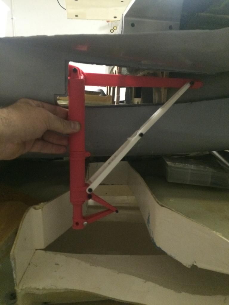
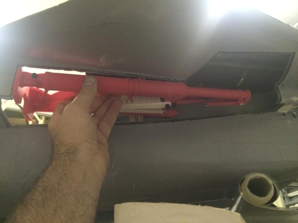
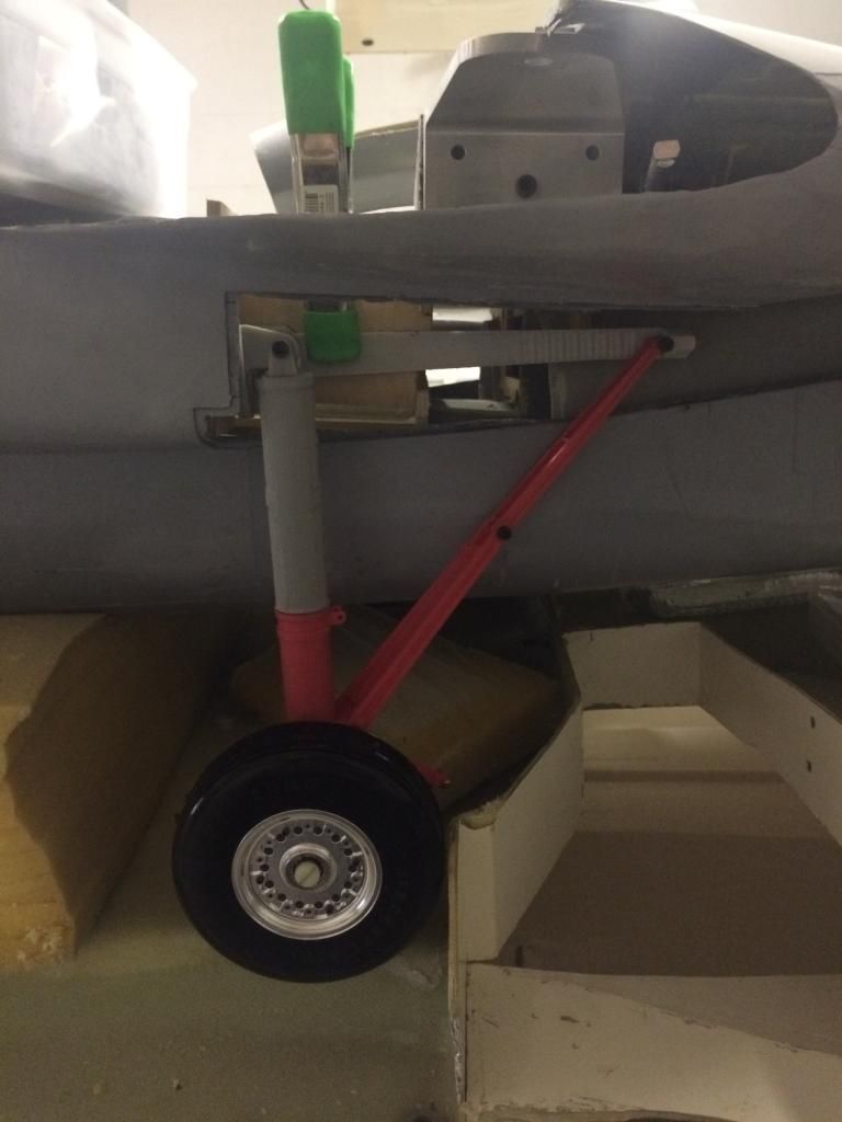
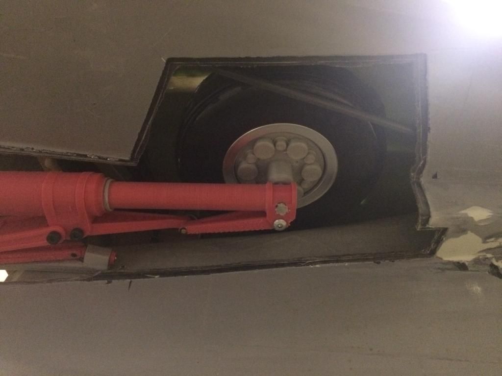
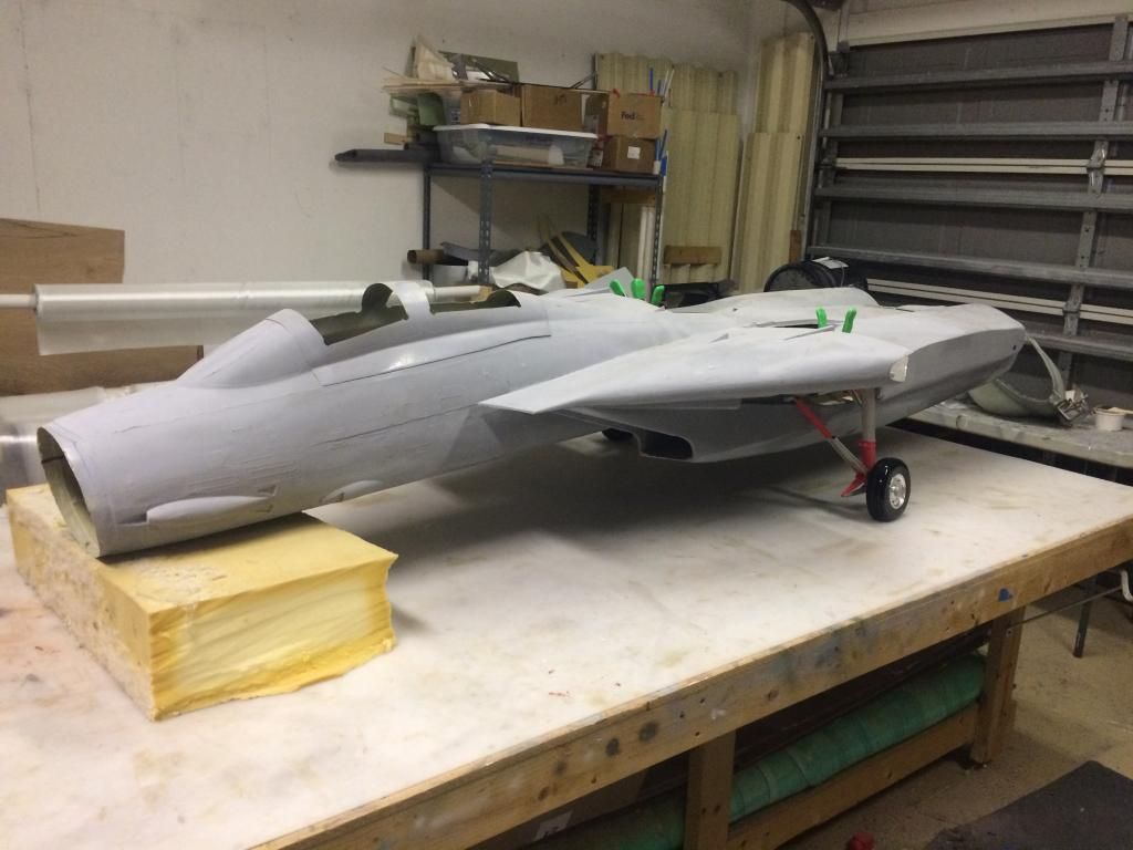
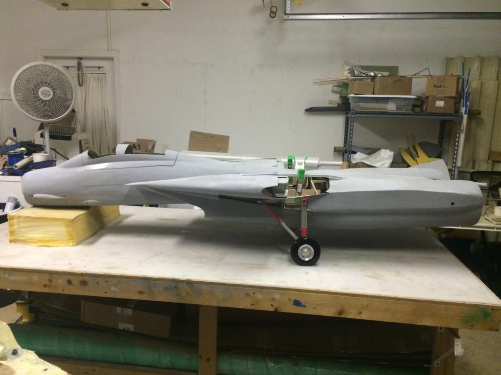
Over 5 years later this thing is finally sitting on something other than foam. Lol. Both main gear are mocked into place. Everything looks great, now its time to get the cylinders and the nose gear designed so i can get some useable gear for this thing.


 10-05-2014, 07:03 AM
#1500
Me either! Im looking forward to and dreading doing #2 and 3, but i think ill end up doing both of those at the same time. #2 will be to test a new lighter layup and if that works well, #3 will get a full house arrangement of detail for competition. Still 3-4 years from that though.

