


Flight controls power requirements and servo sizing


 05-04-2014, 07:37 PM
#78
Oli,
I am having some issues with figuring out the correct parameters for a Flap calculation and I was wondering if you could help?
Here are the parameters that I have tried:
The issue I am having is selecting the correct values for Rs +/- and Rc +/-
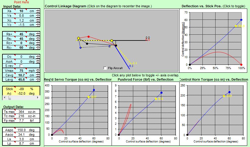
I believe that Rc + should be 0 deg and Rc- should be 60 deg, but this yields a strange diagram in the excel program.
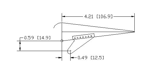
The flap uses a live hing and the hing point is on the bottom skin of the wing.
I drew up the surface in Autocad to visually verify, and it should work, can you help?
I am having some issues with figuring out the correct parameters for a Flap calculation and I was wondering if you could help?
Here are the parameters that I have tried:
The issue I am having is selecting the correct values for Rs +/- and Rc +/-
I believe that Rc + should be 0 deg and Rc- should be 60 deg, but this yields a strange diagram in the excel program.
The flap uses a live hing and the hing point is on the bottom skin of the wing.
I drew up the surface in Autocad to visually verify, and it should work, can you help?
05-04-2014, 11:13 PM
#79

Thread Starter

That's because you do not use the offset function "0c".
Here is how you should do it. 0c is specifically designed for flaps.
In the example below i used a takeoff position of 15 degrees and offset the control by -15 degrees.
The deflection then becomes 45 down to keep the max deflection of 60 degrees.
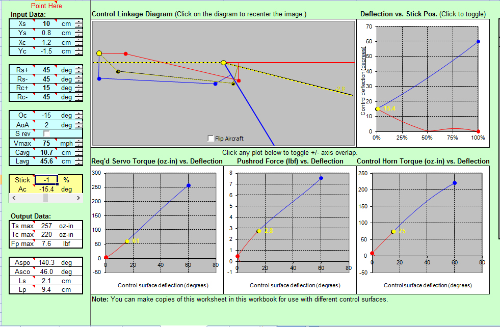
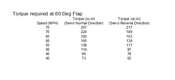
Note that the torque requirement for a deflection of 15 degrees at 75 mph is 61 oz-in. This is good.
As you deflect your flaps towards 60 degrees you want to slow down, as 75 mph would require 257 oz-in of torque from the servo at least.
Here is how you should do it. 0c is specifically designed for flaps.
In the example below i used a takeoff position of 15 degrees and offset the control by -15 degrees.
The deflection then becomes 45 down to keep the max deflection of 60 degrees.
Note that the torque requirement for a deflection of 15 degrees at 75 mph is 61 oz-in. This is good.
As you deflect your flaps towards 60 degrees you want to slow down, as 75 mph would require 257 oz-in of torque from the servo at least.
05-05-2014, 03:30 AM
#80

My Feedback: (5)
Join Date: Dec 2011
Location: Holland Patent,
NY
Posts: 717
Likes: 0
Received 0 Likes
on
0 Posts
Oli,
Great thread especially for us scratch builders. Got a question on flap servo requirements-where the hinge pivot point is below the wing surface. This occurs when using Fun-Key hinges (from Yellow A/C) for their F/A-18 and similar jets. With their medium size hinges, the pivot point is about 10 mm below the wing/flap surface. This type of hinge yields a semi-Fowler type movement of the flap. Also, what is the recommended position of the flap control horn with this setup.? I'd appreciate your thoughts and guidance on this. Thanz in advance.
Rgds,
Art ARRO
05-05-2014, 12:52 PM
#81
That's because you do not use the offset function "0c".
Here is how you should do it. 0c is specifically designed for flaps.
In the example below i used a takeoff position of 15 degrees and offset the control by -15 degrees.
The deflection then becomes 45 down to keep the max deflection of 60 degrees.
Note that the torque requirement for a deflection of 15 degrees at 75 mph is 61 oz-in. This is good.
As you deflect your flaps towards 60 degrees you want to slow down, as 75 mph would require 257 oz-in of torque from the servo at least.
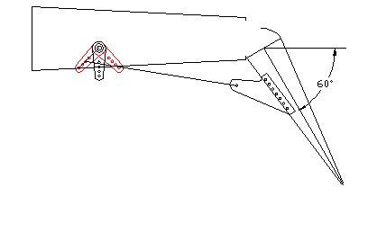
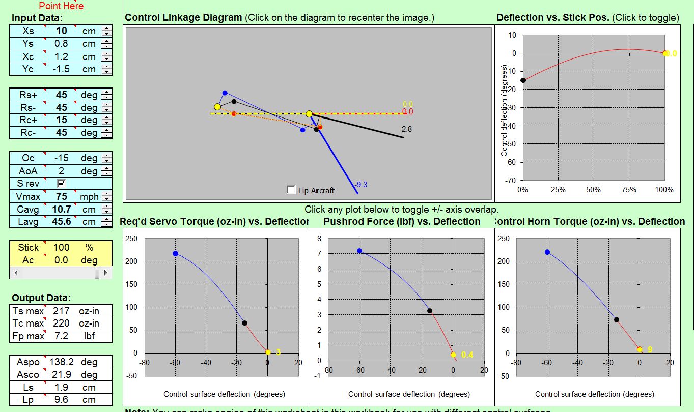
I entered the same numbers you used and came up with the same results, however I still have a question, see photo.
In the cad drawing I have the servo arm drawn as I though it should be which is different than the diagram in the simulation.
It is good to see that the program yields very close results as the drawing, in this case the distance from center line to the tip at full deflection, the Autocad drawing shows 9.7cm and the program shows 9.3 cm, which I think is close...
05-05-2014, 12:54 PM
#82
Oli,
Great thread especially for us scratch builders. Got a question on flap servo requirements-where the hinge pivot point is below the wing surface. This occurs when using Fun-Key hinges (from Yellow A/C) for their F/A-18 and similar jets. With their medium size hinges, the pivot point is about 10 mm below the wing/flap surface. This type of hinge yields a semi-Fowler type movement of the flap. Also, what is the recommended position of the flap control horn with this setup.? I'd appreciate your thoughts and guidance on this. Thanz in advance.
Rgds,
Art ARRO
Great thread especially for us scratch builders. Got a question on flap servo requirements-where the hinge pivot point is below the wing surface. This occurs when using Fun-Key hinges (from Yellow A/C) for their F/A-18 and similar jets. With their medium size hinges, the pivot point is about 10 mm below the wing/flap surface. This type of hinge yields a semi-Fowler type movement of the flap. Also, what is the recommended position of the flap control horn with this setup.? I'd appreciate your thoughts and guidance on this. Thanz in advance.
Rgds,
Art ARRO
I am not sure how to lower the hing point in the program.
Last edited by RCISFUN; 05-05-2014 at 05:40 PM.
05-05-2014, 01:11 PM
#83
Other interesting information
I was making a chart from my flap example with declining air speed when I accidentally selected the servo reverse function, the torque requirements went down...
I charted both normal and reverse servo functions.
I was making a chart from my flap example with declining air speed when I accidentally selected the servo reverse function, the torque requirements went down...
I charted both normal and reverse servo functions.
Last edited by RCISFUN; 05-05-2014 at 05:41 PM.
05-05-2014, 10:44 PM
#85
Thread Starter
05-05-2014, 10:46 PM
#87
Thread Starter
I have not had the time to implement offset hinges in the program yet...
05-05-2014, 10:54 PM
#88
Thread Starter
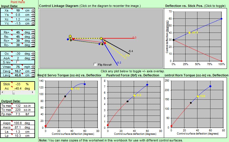
There is always one possible solution to ensure a proper cinematics with reasonable inputs.
The red curve is non linear in this example because the servo arm is nearly aligned with the control link for almost all the deflection between 0 degrees and -15 degrees.
The difference between your CAD and the simulation is the servo offset at neutral. Note that this can be changed by entering a different value of Oc.
05-06-2014, 01:59 AM
#89
My Feedback: (1)
Join Date: Feb 2002
Location: private, UNITED KINGDOM
Posts: 3,672
Likes: 0
Received 26 Likes
on
16 Posts
Since flap travel is 60 degres, half flap (which will equat to servo centre) is 30, so in the Oc box put in -30, not -15. Then your Rc+ and Rc- both should be +30, i.e. 30 degrees either side of a -30 centre value (the Oc value). Now you will get a proper diagram showing a sensible servo output arm, and sensible torque graphs.
At first, when you put the Tx switch to the mid position the flap will go to about 30 degrees down. Simply adjust the Tx flap control/servo centre point until you get the required travel.
05-06-2014, 03:41 AM
#90
Oli and HarryC
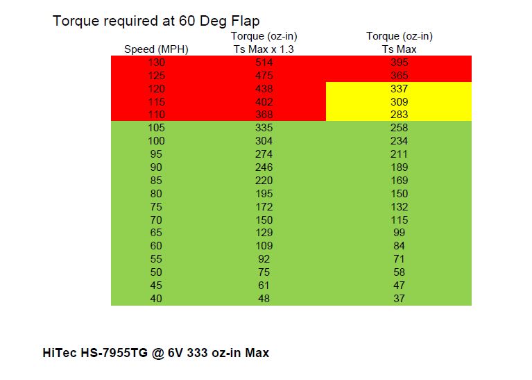
Thank you very much, I corrected the chart and the torque numbers appear more favorable, I created a new chart using the HI TEC HS 7955TG as the servo.
The chart does illustrate what happens when deploying full flaps too soon.
With the proper Oc and Rc+ & Rc- numbers the geometry looks good as compared to my drawing and the strange anomalies are gone.
