


Let's gasify a Vanquish
 09-22-2013, 07:37 PM
#126
Senior Member
Thread Starter
Dear Matt;
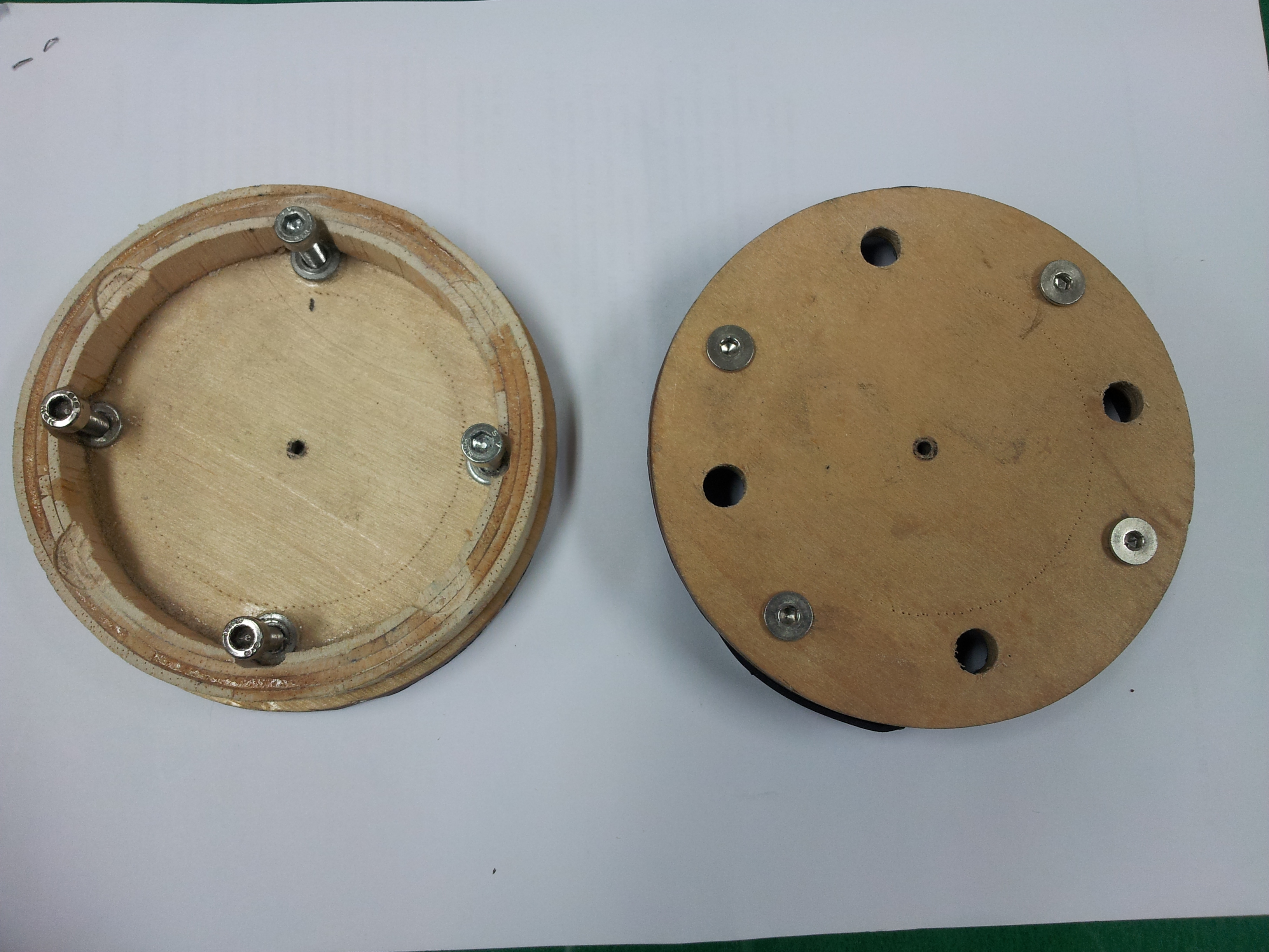
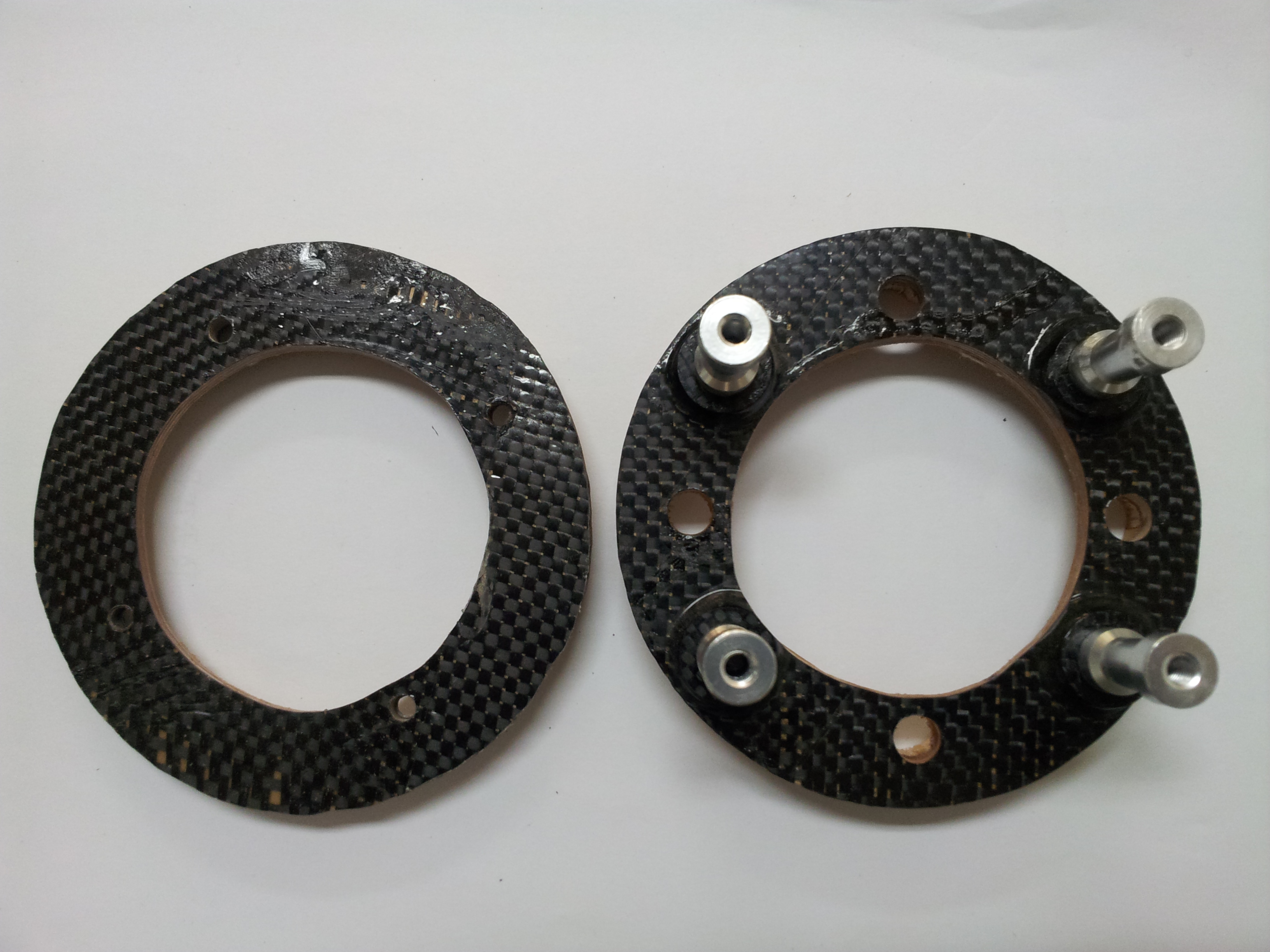
I just made a ring, front plate and back plate.
Diameter of the ring are 88 mm inner diameter and 107 mm, so 9.5 mm thickness.
Thickness of Front plate is 5.5 mm (2x3/32'' +GF), and that of back plate is 4.5 mm (2/32"+1/16" +GF). Diameter are both 111 mm.
Four holes in the front plate (in the picture) are for engine mount of OS GT33.
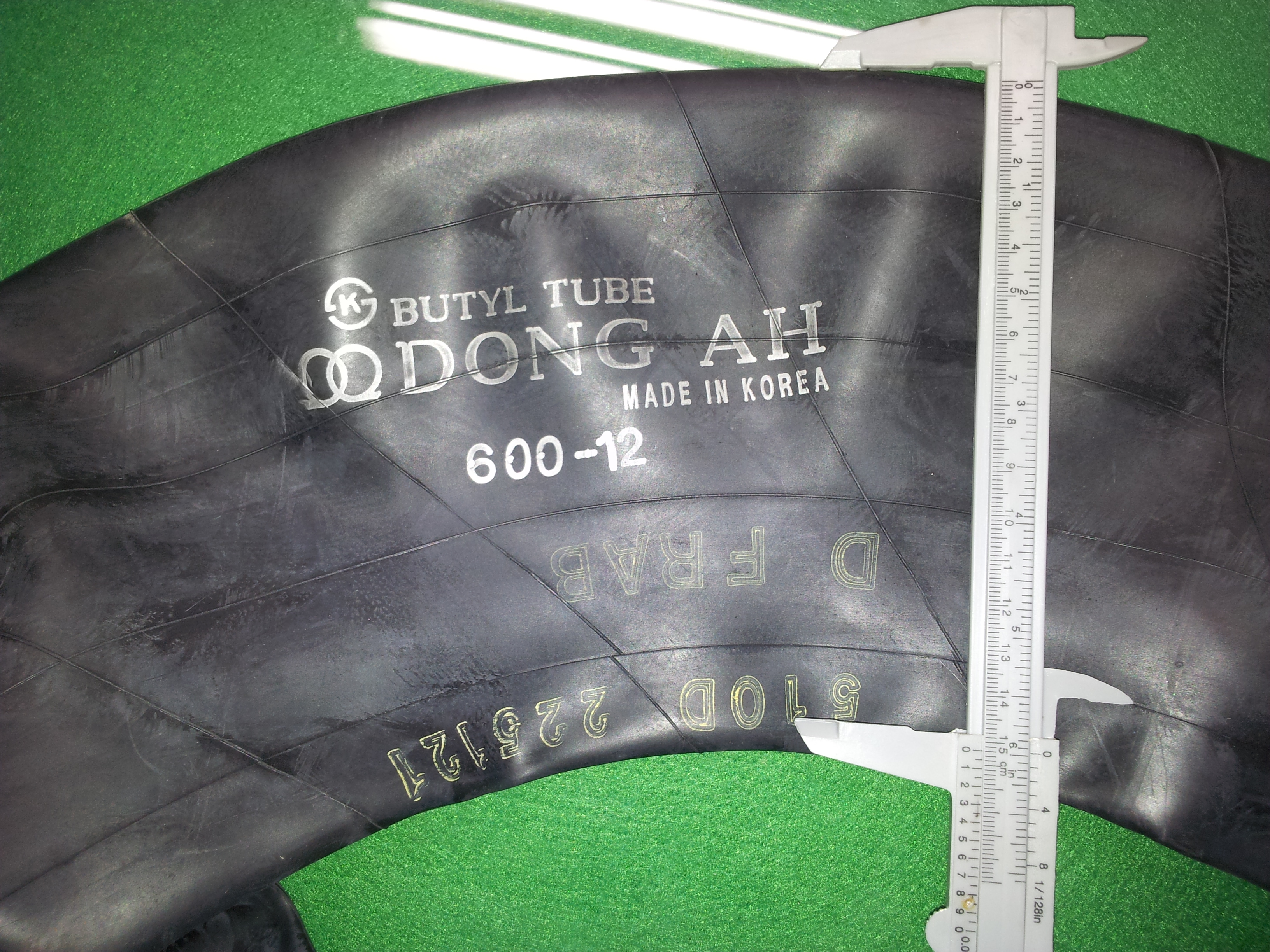
However, I can not find proper inner tube. One that I have is from a small plow trackter with a circumference of 34 cm, which just fit on the ring without stretch.
I am considering to cut the rubber, and make a tight rubber ring by overlapping two ends pasting with gorilla super glue.
Please, suggest any comment. Thanks Matt.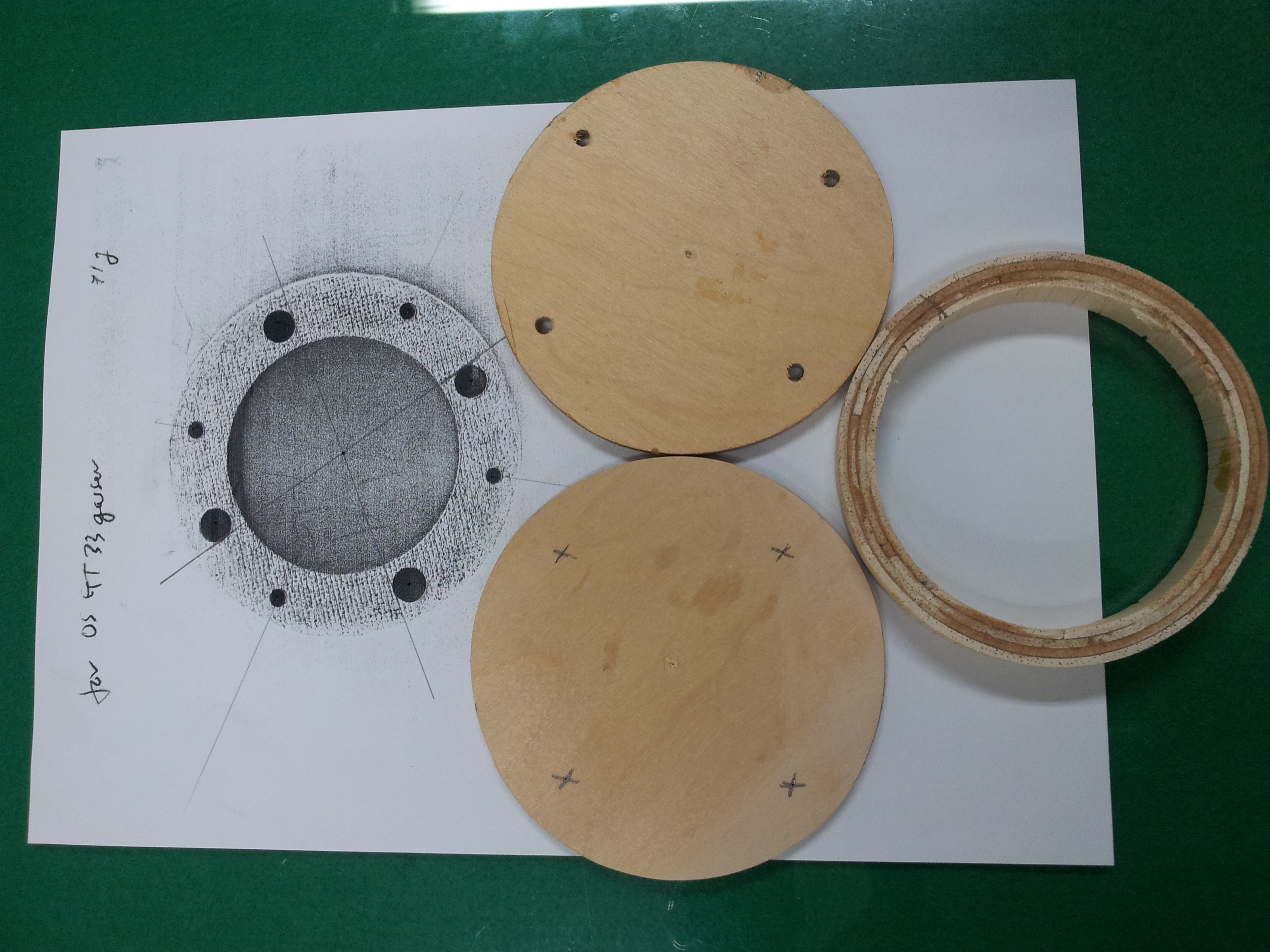
I just made a ring, front plate and back plate.
Diameter of the ring are 88 mm inner diameter and 107 mm, so 9.5 mm thickness.
Thickness of Front plate is 5.5 mm (2x3/32'' +GF), and that of back plate is 4.5 mm (2/32"+1/16" +GF). Diameter are both 111 mm.
Four holes in the front plate (in the picture) are for engine mount of OS GT33.
However, I can not find proper inner tube. One that I have is from a small plow trackter with a circumference of 34 cm, which just fit on the ring without stretch.
I am considering to cut the rubber, and make a tight rubber ring by overlapping two ends pasting with gorilla super glue.
Please, suggest any comment. Thanks Matt.
It's a great start Choihjin. If the tractor rubber is all you have, try it but don't cut it. Hopefully it is a snug fit and not sloppy. You want to make sure it is very clean with all of the anti stick material, usually soap, is removed. You want to make sure that the rubber is sanded well with 80 grit or 120 grit in the area that will be glued onto the wood. You want to expose fresh rubber and deglaze the surface of the rubber before using ca.
How thick is the rubber? I use 2 layers of 1.3 mm thick rubber and that is working out well. The first layer is glued on the edge of the rubber onto the inside lip of the ply faces. The balsa spacer is undersized about 1.5mm on the radius, all around, compared to the ply faces. The second layer is glued on the edges of the plywood rings, overlapping the first layer. Only the edges are glued. The mid section of the rubber is allowed to move free to snub out the vibrations
For mounting stand offs off the front face, I use flat headed screws. I add a small ply piece about 6mm thick behind the screw holes, I drill and tap the backing and then use a chamfering tool which makes sure the flat head screw screws in flat. I think your machinist friend should have all the tools you need...
Good luck, you have a great start
 09-22-2013, 10:55 PM
#128
Member
My Feedback: (1)
Join Date: Feb 2008
Location: Daegu, SOUTH KOREA
Posts: 54
Likes: 0
Received 0 Likes
on
0 Posts
Dear Matt:
Thanks for your prompt reply.
The thickness of the rubber is 1.0-1.1 mm, which just snug fit on the balsa space (width 15 mm).
You recommend not to cut it, just glue it on the ring. Thanks it make me clear.
I have organized all your posting about soft mount in RU, which is 21 pages. I already figure it out in my brain.
The balsa spacer is undersized about 1.5mm on the radius, all around, compared to the ply faces.
Mine is also undersized 1.5-2 mm on the radius to the ply faces. I will remove some by grinding off on sandpaper.
Yes, I will use normal M5 with sockethead cap screws, or I have to order some flathead screws.
BTW did you made the standoff mount by yourself? One I have is bought from Hobby King (M5 both end threaded, 6.0 cm long)
It is too long (60 mm) and the thickness of soft mount will become 25-26 mm, so I will use it without ply pieces (6 mm thick), but I will strengthen the front plate with a carbon fiber. Do you think it will be fine?
Thanks
Tele1974, please reference it which is the original Matt's posting in RU.
http://www.rcuniverse.com/forum/m_62...tm.htm#6285026
Last edited by choihjin; 09-23-2013 at 12:21 AM.
09-23-2013, 06:05 AM
#129
Senior Member
Thread Starter
Dear Matt:
Thanks for your prompt reply.
The thickness of the rubber is 1.0-1.1 mm, which just snug fit on the balsa space (width 15 mm).
You recommend not to cut it, just glue it on the ring. Thanks it make me clear.
I have organized all your posting about soft mount in RU, which is 21 pages. I already figure it out in my brain.
The balsa spacer is undersized about 1.5mm on the radius, all around, compared to the ply faces.
Mine is also undersized 1.5-2 mm on the radius to the ply faces. I will remove some by grinding off on sandpaper.
Yes, I will use normal M5 with sockethead cap screws, or I have to order some flathead screws.
BTW did you made the standoff mount by yourself? One I have is bought from Hobby King (M5 both end threaded, 6.0 cm long)
It is too long (60 mm) and the thickness of soft mount will become 25-26 mm, so I will use it without ply pieces (6 mm thick), but I will strengthen the front plate with a carbon fiber. Do you think it will be fine?
Thanks
Tele1974, please reference it which is the original Matt's posting in RU.
http://www.rcuniverse.com/forum/m_62...tm.htm#6285026
Thanks for your prompt reply.
The thickness of the rubber is 1.0-1.1 mm, which just snug fit on the balsa space (width 15 mm).
You recommend not to cut it, just glue it on the ring. Thanks it make me clear.
I have organized all your posting about soft mount in RU, which is 21 pages. I already figure it out in my brain.
The balsa spacer is undersized about 1.5mm on the radius, all around, compared to the ply faces.
Mine is also undersized 1.5-2 mm on the radius to the ply faces. I will remove some by grinding off on sandpaper.
Yes, I will use normal M5 with sockethead cap screws, or I have to order some flathead screws.
BTW did you made the standoff mount by yourself? One I have is bought from Hobby King (M5 both end threaded, 6.0 cm long)
It is too long (60 mm) and the thickness of soft mount will become 25-26 mm, so I will use it without ply pieces (6 mm thick), but I will strengthen the front plate with a carbon fiber. Do you think it will be fine?
Thanks
Tele1974, please reference it which is the original Matt's posting in RU.
http://www.rcuniverse.com/forum/m_62...tm.htm#6285026
I use thin ca glue to glue down the rubber edges directly onto the ply wood. I first fit the rubber and then apply the ca, hold it until it kicks off and proceed to the next section. I work on one face at a time, gluing the edge completely all around before moving to the second face.
I then install the second facing loosely. I turn the assembly so that the facing to be glued to the rubber is on a hard, sturdy surface. Then with a flat screwdriver blade I push the rubber down to meet the plywood, and apply thin ca. Usually the rubber needs a little stretch to get snug against the plywood face. I hold each section until ca kicks off and proceed all around
Once the first rubber layer has been installed, I sand the plywood edges flush with the rubber surface, making the plywood ready for the second rubber layer. Fresh wood and freshly exposed rubber adhere great to one another. If some glue has gotten on the plywood somehow, I sand that area well to expose fresh wood.
The second layer is longer than necessary and fits over the whole mount. I usually work on one edge at a time. I roll the rubber back and apply medium ca to the ply ring. The rubber is flipped over the ca and allowed to kick off while holding the rubber firm against the ply ring. Then the second rubber end is rolled back and the same treatment is done to the second ring.
Then, with a sharp razor, the rubber is trimmed flush to the faces.
Carbon cloth may be applied now to each ply face or much earlier before final assembly is started. In my mounts I tend to apply the carbon first before assembly. It is easier to apply without screws in the way.
The final treatment is to remove the center section of plywood leaving a hole in the middle of the mount, and fuel proofing the exposed wood. The hole removes unnecessary weight and tends to house the front section of the carburetor and the stand offs I use are just long enough to clear the mixture screws on the walbro. That's it. The completed mounted usually weighs around 2 1/2 ounces (65 to 70 grams), but that depends alot on the hardware and plywood thickness used. The plywood I use is 3mm a/c birch (1/8") at least 5 ply and Usually 7 ply.
I also cut a hole in the firewall further reducing weight. The FW hole corresponds roughly with the hole in the mount...
09-23-2013, 06:17 AM
#130
Senior Member
Thread Starter
The thickness should be around 0.600 but I have built mounts with spacer thickness as thick as 1 1/2". They all work well to snub out the high freq vibes. Only a low frequency shake remains which is not really destructive to the airframes.
A practical balsa spacer thickness is 0.6" to 0.8", in other words.
09-23-2013, 06:57 PM
#131
Member
My Feedback: (1)
Join Date: Feb 2008
Location: Daegu, SOUTH KOREA
Posts: 54
Likes: 0
Received 0 Likes
on
0 Posts
Thank a lot for your kind instructions.
I ordered four stand-off mount M5-30mm(L) both end threaded, and four carbon engine mount washers (18mm(OD)x5mm(ID)x4mm(thickness)).
And I bought flat-head bolts (M5x25mm and M5x20mm), which you suggested to use. I understand now this flat-head bolts are good for our soft mount with a limited balsa space. Waiting for stand-off mount delivered, I am covering carbon cloth on the front and back plate. Instead of your 6mm balsa spacer, carbon washers (4 mm thick) will be pasted with epoxy glue, then total thickess will be 10 mm. I an going to Glue the flat-head bolts on front plate with just epoxy. Do you think it will be fine for long time use?
BTW, in the early of this thread, your back firewall is made of 1/4" grained balsa carbon sandwich. I am not familiar with grained balsa. What is it?
I will be back, Matt.
Regards
09-24-2013, 06:50 AM
#132
Senior Member
Thread Starter
Thank a lot for your kind instructions.
I ordered four stand-off mount M5-30mm(L) both end threaded, and four carbon engine mount washers (18mm(OD)x5mm(ID)x4mm(thickness)).
And I bought flat-head bolts (M5x25mm and M5x20mm), which you suggested to use. I understand now this flat-head bolts are good for our soft mount with a limited balsa space. Waiting for stand-off mount delivered, I am covering carbon cloth on the front and back plate. Instead of your 6mm balsa spacer, carbon washers (4 mm thick) will be pasted with epoxy glue, then total thickess will be 10 mm. I an going to Glue the flat-head bolts on front plate with just epoxy. Do you think it will be fine for long time use?
BTW, in the early of this thread, your back firewall is made of 1/4" grained balsa carbon sandwich. I am not familiar with grained balsa. What is it?
I will be back, Matt.
Regards
I ordered four stand-off mount M5-30mm(L) both end threaded, and four carbon engine mount washers (18mm(OD)x5mm(ID)x4mm(thickness)).
And I bought flat-head bolts (M5x25mm and M5x20mm), which you suggested to use. I understand now this flat-head bolts are good for our soft mount with a limited balsa space. Waiting for stand-off mount delivered, I am covering carbon cloth on the front and back plate. Instead of your 6mm balsa spacer, carbon washers (4 mm thick) will be pasted with epoxy glue, then total thickess will be 10 mm. I an going to Glue the flat-head bolts on front plate with just epoxy. Do you think it will be fine for long time use?
BTW, in the early of this thread, your back firewall is made of 1/4" grained balsa carbon sandwich. I am not familiar with grained balsa. What is it?
I will be back, Matt.
Regards
Cross grained balsa is a common material used extensively in boat construction. 1/4" thickness has the grain ( the fibers) running along the thickness dimension rather than length or width. Once carbon cloth is epoxied on both sides, the plate has great strength but weighs very little. If you choose this approach, two things:
1- to make the firewall, I apply the carbon and epoxy to both sides and place the assembly on release surfaces like 0.25 mm mylar, on both sides. Then the whole assembly is backed up with 3/4" plywood (about 20mm) and then placed in a vice and locked firm to cure
2- the areas where the bolts are inserted are reinforced. I use short length of carbon tubing for reinforcements. I add the carbon tubes after the firewall has cured and has been fitted (but not glued yet) in the fuse. I also add a blind nut on the back side which has been mounted on a 4mm, 1cm dia plywood disc. Works great for 55-60 cc engines too, so it is plenty strong for 30cc engines. If you have a boat supply shop close by, check with them. Chances are they have it in stock
Last edited by MTK; 09-24-2013 at 06:58 AM.
09-24-2013, 04:07 PM
#133
Member
My Feedback: (1)
Join Date: Feb 2008
Location: Daegu, SOUTH KOREA
Posts: 54
Likes: 0
Received 0 Likes
on
0 Posts
Dear Matt;
I am learning a lot from you, Thanks a lot.
I got some knowledge from Google, but your descriptions are much valuable for me practically.
Still waiting for stand-off mount, I am almost ready to the final.
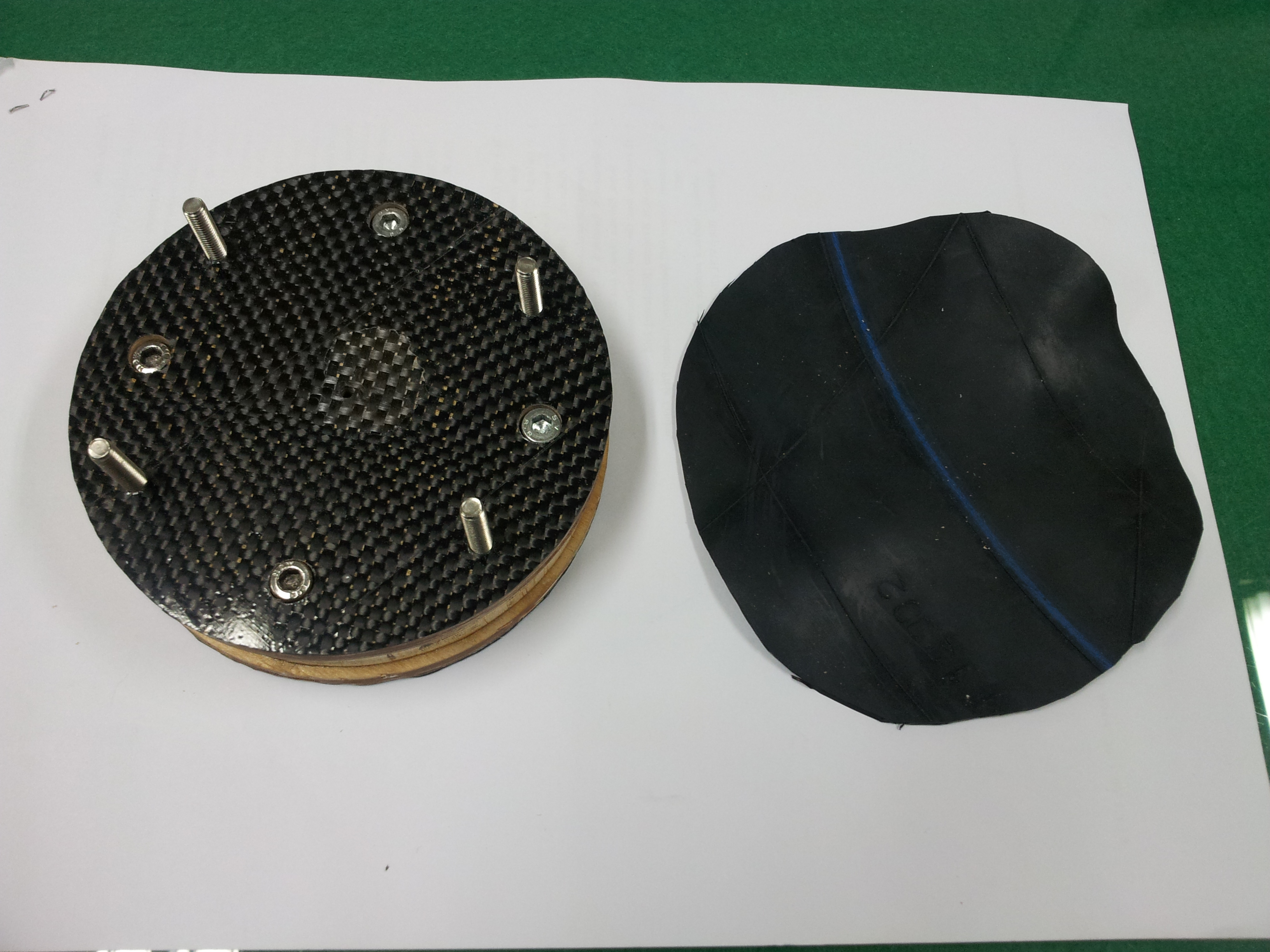
As you mentioned on fastening the flat-heat bolts on the front plate with carbon washer, I drilled the front plate and milled with a count sink, which I found and have in my BOSCH drill sets.
I just put all bolts in the plates to make sure them in right place, and pre-assembled.
The rubber piece (from same inner tube) will be used for the back-half balsa ring after glued together and divided.
After I got the carbon washer, I will glue it on the front-side of the front plate, and tighten with the flat-head bolts through hole from the wooden side, with some epoxy.
Thanks a lot.
I am learning a lot from you, Thanks a lot.
I got some knowledge from Google, but your descriptions are much valuable for me practically.
Still waiting for stand-off mount, I am almost ready to the final.
As you mentioned on fastening the flat-heat bolts on the front plate with carbon washer, I drilled the front plate and milled with a count sink, which I found and have in my BOSCH drill sets.
I just put all bolts in the plates to make sure them in right place, and pre-assembled.
The rubber piece (from same inner tube) will be used for the back-half balsa ring after glued together and divided.
After I got the carbon washer, I will glue it on the front-side of the front plate, and tighten with the flat-head bolts through hole from the wooden side, with some epoxy.
Thanks a lot.
09-25-2013, 05:50 AM
#134
Senior Member
Thread Starter
Choihjin,
I think you got the essential parts pretty well. The next mount will be much easier to build.
I'm not sure if you have a balsa spacer for the front facing. I don't see it shown in the photo. It isn't absolutely necessary to have a spacer for the front facing tho, so you should be fine. You should try and keep the bolt heads from hitting the balsa spacer on the back facing. When the engine is idling, the mount allows a lot of shake and the bolt heads could do some damage if allowed to hit anywhere.
Looks to me that you are just about ready to install the rubber rings. Excellent job!
You may want to reduce the length of the flat head bolts. I usually expose about 7-8 threads; I use a drop of blue loctite (the removable type) and the stand offs don't move until I move them.
Once you remove the center area of the mount you would be surprised at how light it is. My mounts for the 33 usually weigh about 65 grams, but mine are a little smaller than yours. Still, yours should be well below 100 grams
09-25-2013, 08:28 PM
#135

Join Date: Jul 2006
Location: Ossining,
NY
Posts: 2,819
Likes: 0
Received 0 Likes
on
0 Posts
Choihjin, sorry to interrupt here, but having built one of these with the expert guidance of Matt, in my opinion the carbon fiber facing is totally unnecessary. Looks cool, but simply fuel-proofing the plywood and the balsa inner rings would have sufficed. I had several hundred flights on mine (with a Syssa 1.80) when I finally removed it for inspection and I was astonished at the excellent condition of the wood and the rubber, and the functionality of the unit as a whole. I was using an engine nosering, however, and that is another part of the equation. I think it is an essential part of the equation, but Matt has vastly more experience in this area and can advise accordingly. I have been flying electric for some time now and have fallen behind in my knowledge of gassers. But I remember vividly how well this isolation mount worked at the time.
09-26-2013, 07:58 AM
#136
Senior Member
Thread Starter
Choihjin, sorry to interrupt here, but having built one of these with the expert guidance of Matt, in my opinion the carbon fiber facing is totally unnecessary. Looks cool, but simply fuel-proofing the plywood and the balsa inner rings would have sufficed. I had several hundred flights on mine (with a Syssa 1.80) when I finally removed it for inspection and I was astonished at the excellent condition of the wood and the rubber, and the functionality of the unit as a whole. I was using an engine nosering, however, and that is another part of the equation. I think it is an essential part of the equation, but Matt has vastly more experience in this area and can advise accordingly. I have been flying electric for some time now and have fallen behind in my knowledge of gassers. But I remember vividly how well this isolation mount worked at the time.
Regards to adding carbon cloth, if the plywood is 3/16" or thicker, carbon is not required. I make my mounts from much thinner material tho, 3/32" birch a/c ply, and carbon cloth adds stiffness. Agreed, it looks great too.
09-26-2013, 08:34 PM
#137
Member
My Feedback: (1)
Join Date: Feb 2008
Location: Daegu, SOUTH KOREA
Posts: 54
Likes: 0
Received 0 Likes
on
0 Posts
Thanks Matt K and Bob for your concern on my soft mount project.
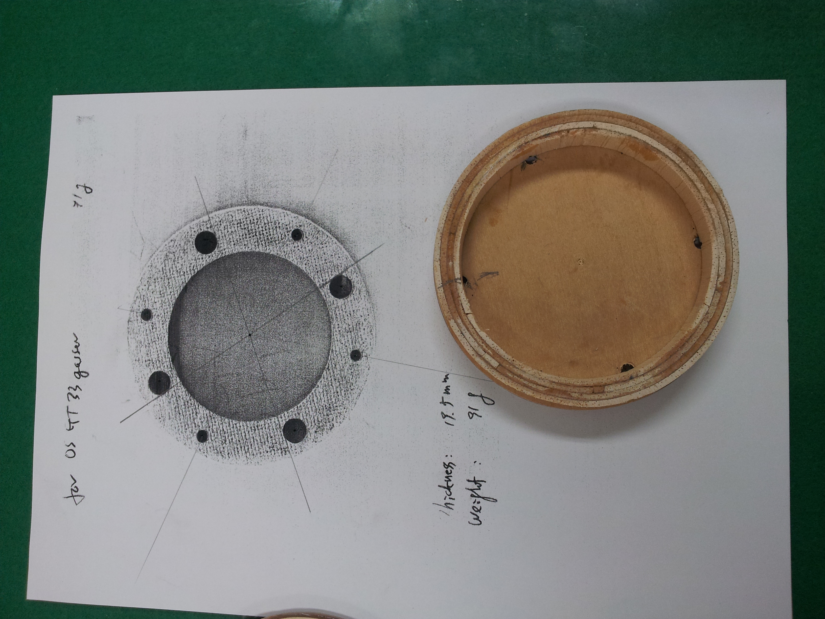
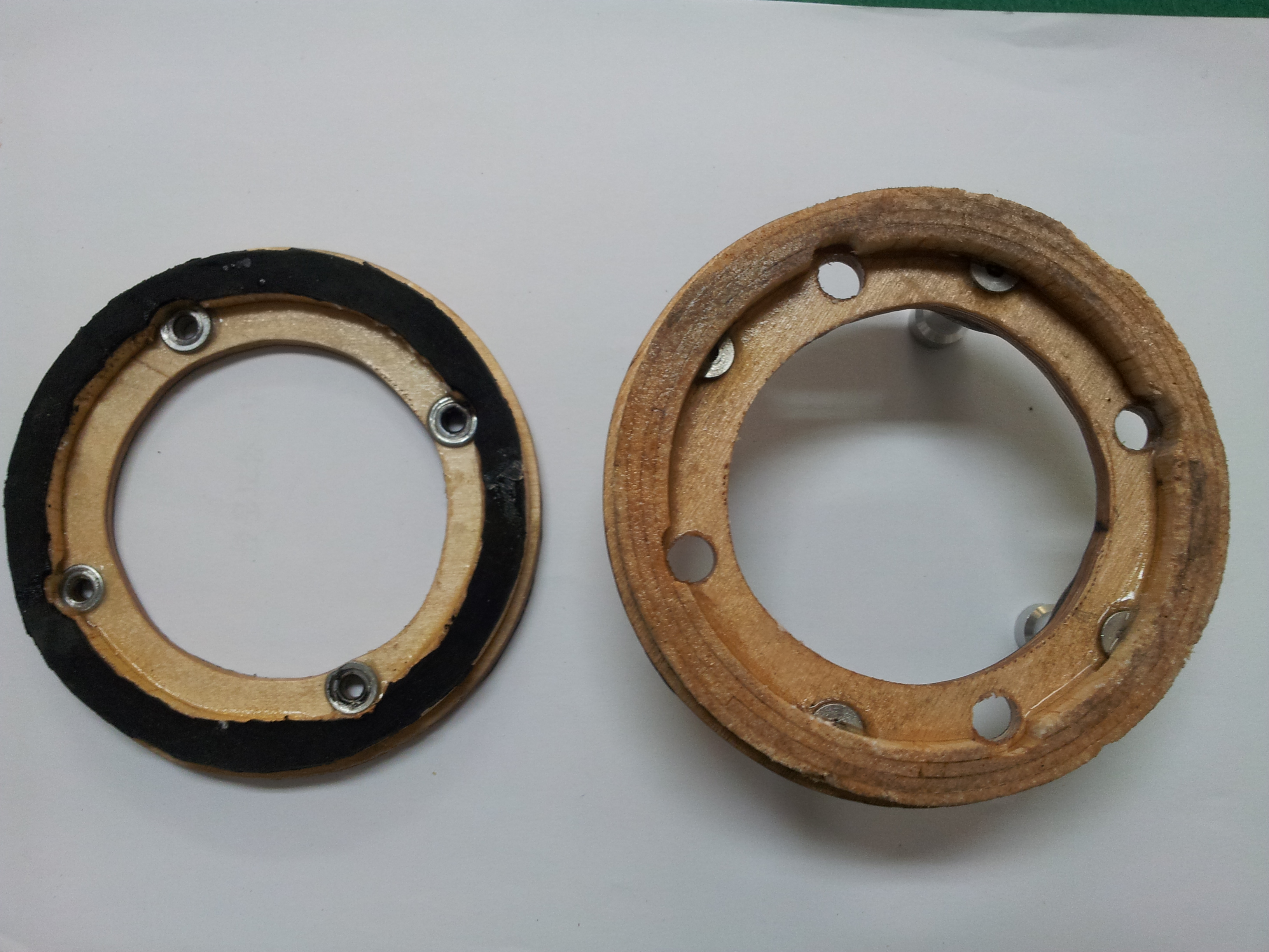
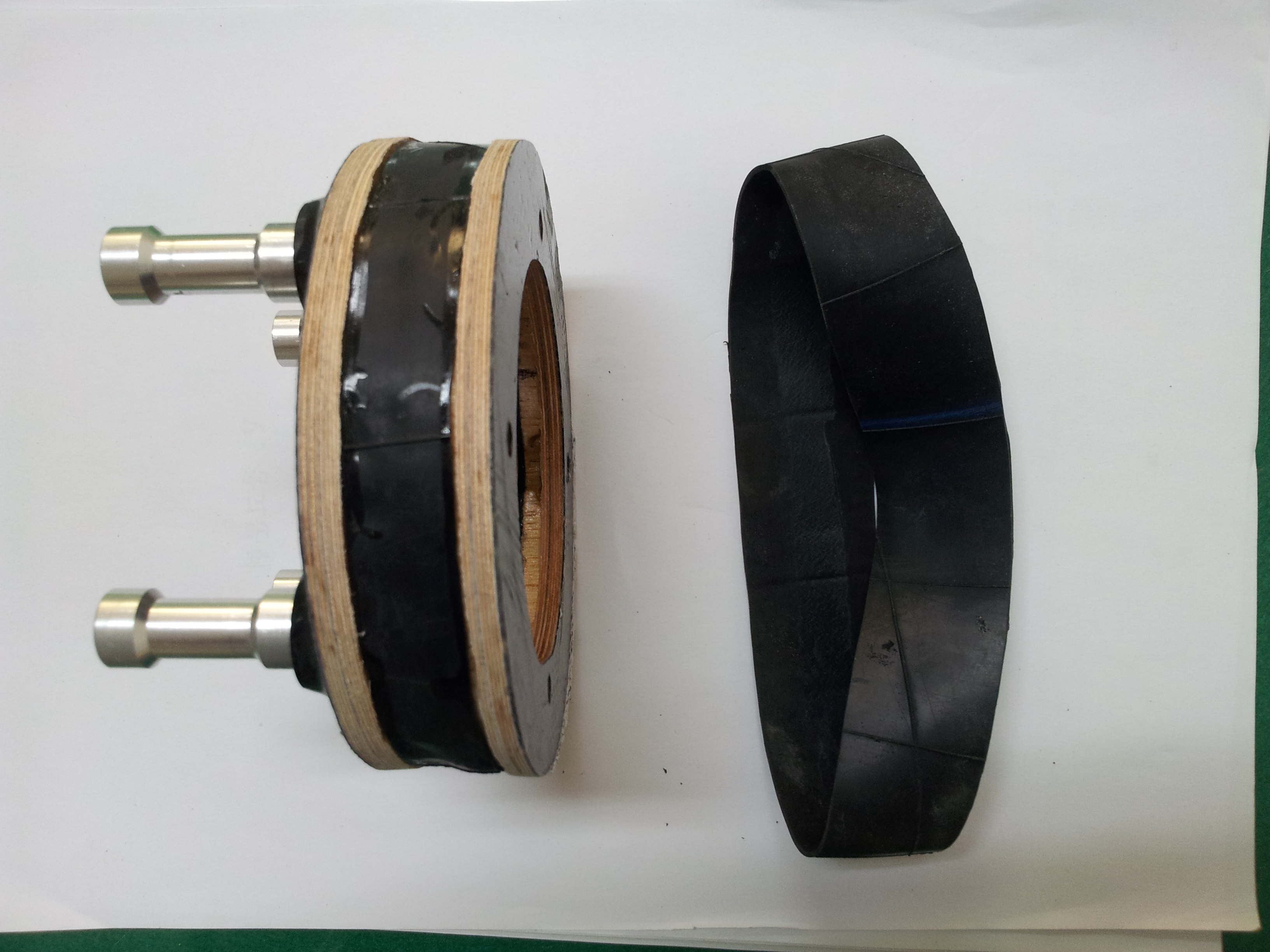
After glued the flat-head bolt with carbon washer on the front plate, and epoxied the balsa ring on the front plate.
After hardened it, then epoxied it to the rear-plate, and tightened with M3 bolt (photo). After hardened it, the balsa ring was divided into two pieces.
On the rear balsa ring a rubber piece was covered and glued with CA (thin regular), and trimmed off some rubber.
09-26-2013, 08:43 PM
#138
Member
My Feedback: (1)
Join Date: Feb 2008
Location: Daegu, SOUTH KOREA
Posts: 54
Likes: 0
Received 0 Likes
on
0 Posts
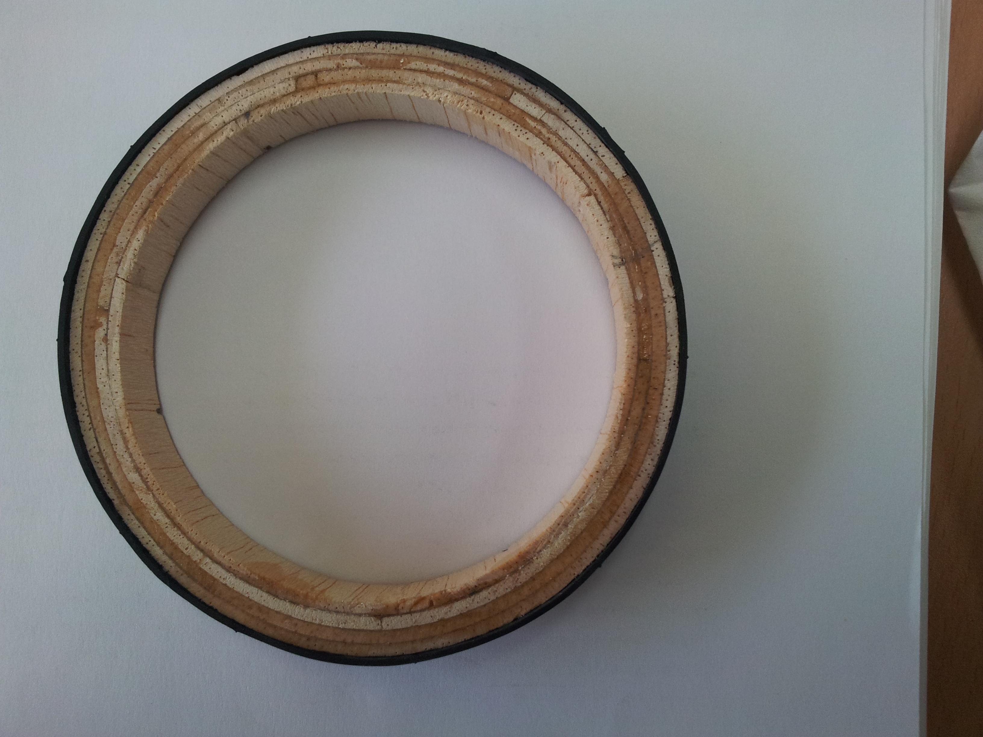
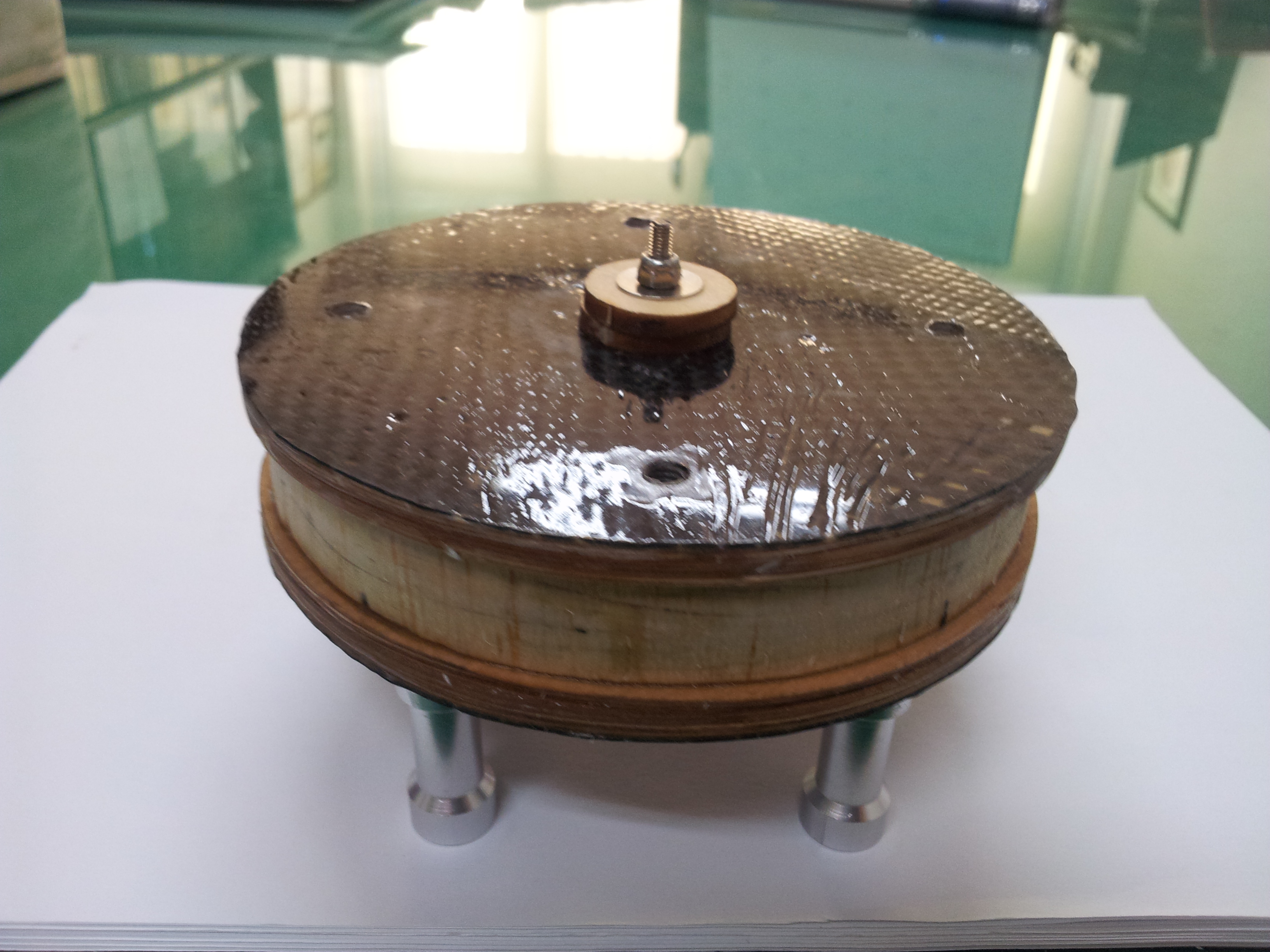
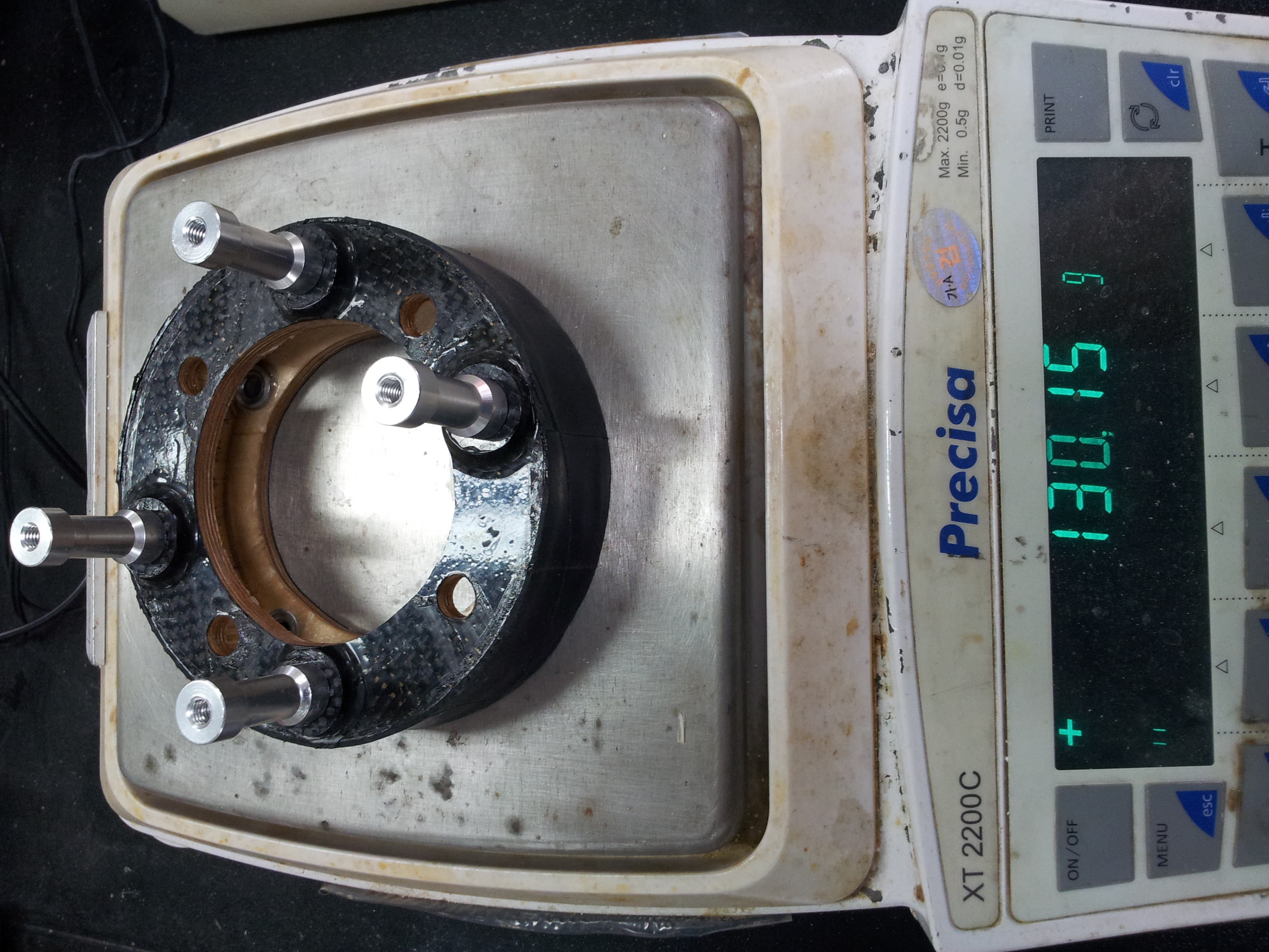
Now I am posting my first hand-made soft mount for OS 33GT.
Thanks a lot Matt. Your guidance really helped me very much.
Mine (130 g) is heavier than what you and I expected. Probably I glued too much epoxy and CA. But it includes four stand-off mounts and beautiful carbon clothes on the front and rear plates.
Now I know what I will do or not for next projects. Thanks again Matt.
Regards
09-27-2013, 06:27 AM
#140
Senior Member
Thread Starter
Now I am posting my first hand-made soft mount for OS 33GT.
Thanks a lot Matt. Your guidance really helped me very much.
Mine (130 g) is heavier than what you and I expected. Probably I glued too much epoxy and CA. But it includes four stand-off mounts and beautiful carbon clothes on the front and rear plates.
Now I know what I will do or not for next projects. Thanks again Matt.
Regards
Thanks a lot Matt. Your guidance really helped me very much.
Mine (130 g) is heavier than what you and I expected. Probably I glued too much epoxy and CA. But it includes four stand-off mounts and beautiful carbon clothes on the front and rear plates.
Now I know what I will do or not for next projects. Thanks again Matt.
Regards
One thing you probably should do is to add a thin ply ring (1/64" is plenty thick) on the balsa spacer where it was cut. You want a smooth surface riding on the rubber facing of the rear balsa spacer. Otherwise, the rough balsa edges will grind the rubber apart quickly.
Good work!! I am interested in its performance. Please report back after flying it a few dozen flights
09-29-2013, 07:58 PM
#141
Senior Member
Join Date: Jan 2007
Location: Olmsted Falls,
OH
Posts: 478
Likes: 0
Received 0 Likes
on
0 Posts
Have you tried any other materials for the front and back plates? I see their is a layer of rubber between the balsa ring and the plate. Does the ring itself providing any damping? I have been thinking about making a soft mount for a couple of years and I keep wondering if it could be made with material that would require less labor.
09-30-2013, 01:54 AM
#142
Member
My Feedback: (1)
Join Date: Feb 2008
Location: Daegu, SOUTH KOREA
Posts: 54
Likes: 0
Received 0 Likes
on
0 Posts
Dear Matt and Bob
The soft mount was tested with 33 gasoline engine on an engine test bed.
I think its performance is great. Please, see the video.
https://www.youtube.com/watch?v=NFshWhB8oSc https://www.youtube.com/watch?v=NFshWhB8oSc Now I am working on the Vanquish, I hope to finish to gasify it by this weekend for its maiden flight.
Regard
Last edited by choihjin; 09-30-2013 at 02:53 AM.
09-30-2013, 12:35 PM
#144
Senior Member
Thread Starter
Several years ago, Budd was offering a soft mount for the 140-160 engines that was made different materials. Facings were glass filled plastic I think. Don't know what glue Jerry used to hold things together
The approach I use is loosely based on Bob Pastorello's mount design, the Pastomount. Simple to make and constructed from standard hobby materials and with standard tools found ubiquitously in the shop. It takes some time to actually do all the steps, but in the end you have a useful product that is very lightweight. A couple of my early mounts are nearing 1000 runs and they are still working fine. The rubber life span is the key...rubber inspection should be done every few hundred runs to make sure cracks in the rubber have not developed
If you have to think this hard to tackle the project, you should try something else. One type mount I have heard others building uses a very thick walled rubber tube, something around 1/2" thick. The rubber is glued directly between the two faces and there is no balsa spacer per se'. It's a different approach and I can't vouch for its effectiveness or life span.
I have given some thought to building something that uses a series of smaller diameter tubes. Something around 1/2" in diameter with a bit thicker wall (around 1/8") stacked around the perimeter of the faces. Have even given some thought to making a mount from a series of Lord mounts again stacked around the perimeter of the faces. At the end of the day, I think weight will go up and effectiveness and life span may be reduced, but since I haven't actually done it, I can't be certain
10-01-2013, 04:45 AM
#145
Join Date: Jul 2006
Location: Ossining,
NY
Posts: 2,819
Likes: 0
Received 0 Likes
on
0 Posts
What material is easier to work with than ply??!!
I never got around to building a second one, but the first one didn't take that long once I got it in my head conceptually how it worked and was able to find the right tube. I think a second one would have taken VERY little time to complete.
I never got around to building a second one, but the first one didn't take that long once I got it in my head conceptually how it worked and was able to find the right tube. I think a second one would have taken VERY little time to complete.
10-13-2013, 08:33 PM
#146
Member
My Feedback: (1)
Join Date: Feb 2008
Location: Daegu, SOUTH KOREA
Posts: 54
Likes: 0
Received 0 Likes
on
0 Posts
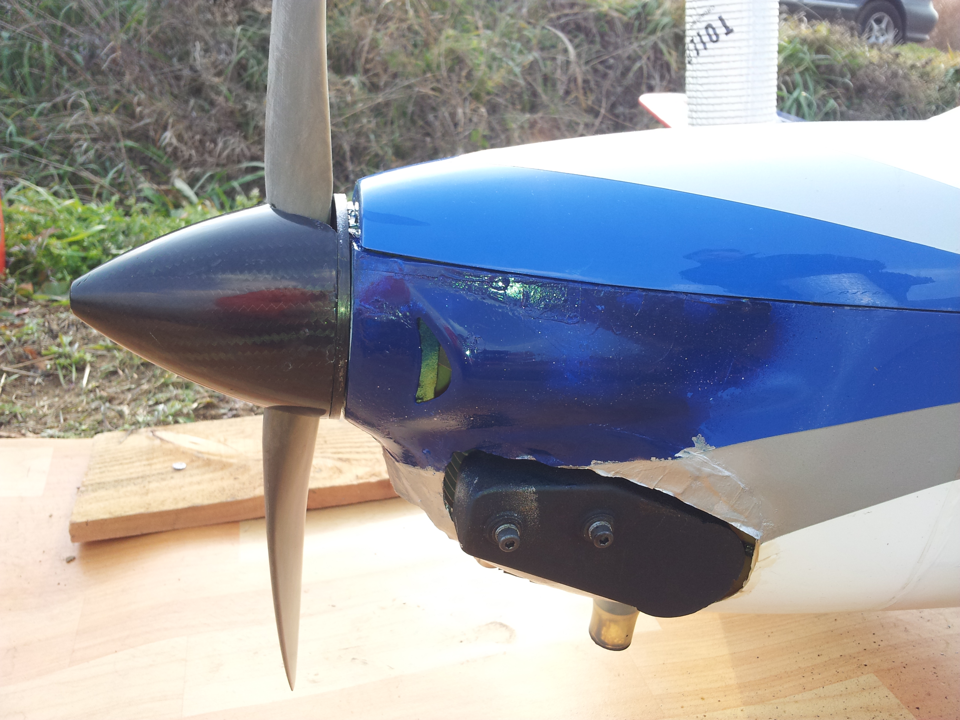
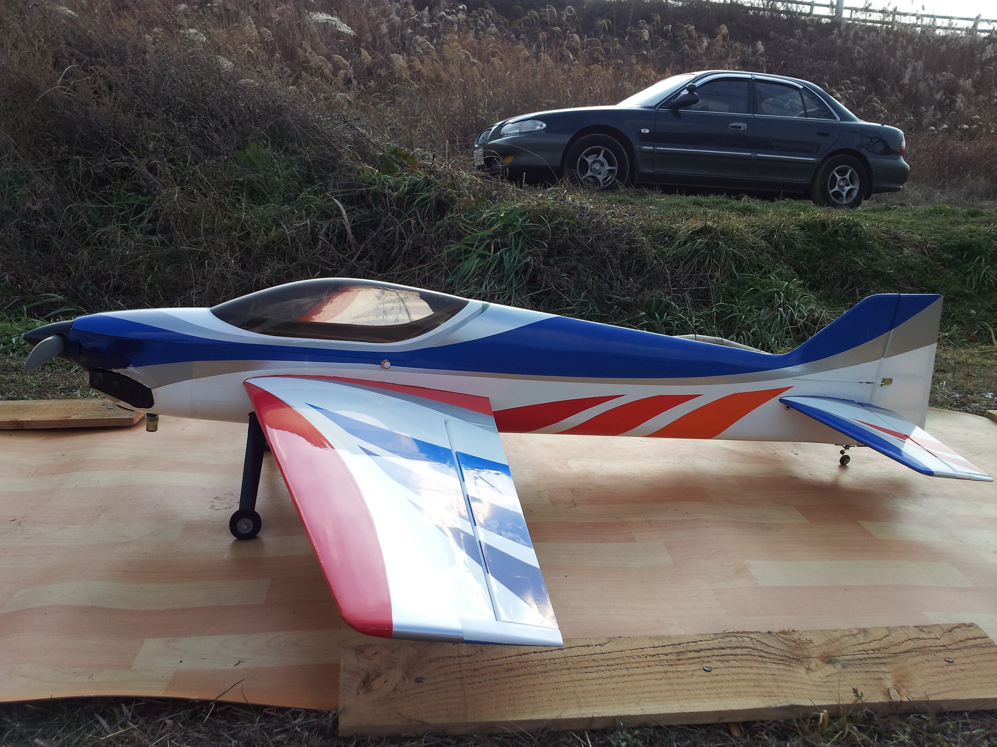
My Vanquish is finally converted to the gas-powered with OS GT 33 gasoline engine, following with Matt's suggested procedure.
With my soft mount, OS Gt 33 engine with stock muffler, 2600 mA/h Lipo for receiver, 1200 mA/h Lipo for ignition, 16 Oz gas tank, a power box and enhanced gear mount, this Vanquish still weigh 4965 g just under 5.0 kg, It flies unlimited high and sound is soft. My club mate did not recognize that it has gasoline engine. Most of them did not believe it is powered with a gas engine. I am not excellent pilot in F3A, but I love this Vanquish, and I will buy one more Vanquish for back-up.
Thanks Matt
http://youtu.be/RrlnHD4TTX4
Last edited by choihjin; 10-13-2013 at 08:36 PM.
10-14-2013, 05:56 AM
#147
Senior Member
Thread Starter
My Vanquish is finally converted to the gas-powered with OS GT 33 gasoline engine, following with Matt's suggested procedure.
With my soft mount, OS Gt 33 engine with stock muffler, 2600 mA/h Lipo for receiver, 1200 mA/h Lipo for ignition, 16 Oz gas tank, a power box and enhanced gear mount, this Vanquish still weigh 4965 g just under 5.0 kg, It flies unlimited high and sound is soft. My club mate did not recognize that it has gasoline engine. Most of them did not believe it is powered with a gas engine. I am not excellent pilot in F3A, but I love this Vanquish, and I will buy one more Vanquish for back-up.
Thanks Matt
http://youtu.be/RrlnHD4TTX4
With my soft mount, OS Gt 33 engine with stock muffler, 2600 mA/h Lipo for receiver, 1200 mA/h Lipo for ignition, 16 Oz gas tank, a power box and enhanced gear mount, this Vanquish still weigh 4965 g just under 5.0 kg, It flies unlimited high and sound is soft. My club mate did not recognize that it has gasoline engine. Most of them did not believe it is powered with a gas engine. I am not excellent pilot in F3A, but I love this Vanquish, and I will buy one more Vanquish for back-up.
Thanks Matt
http://youtu.be/RrlnHD4TTX4
Just one word of caution, the landing gear block has been somewhat of a problem for a few people. But as long as you land of the runway, it should be fine....
11-30-2013, 10:06 AM
#148
Member
My Feedback: (1)
Join Date: Feb 2008
Location: Daegu, SOUTH KOREA
Posts: 54
Likes: 0
Received 0 Likes
on
0 Posts
Hi, Matt.
I have so far flown my gas mod Vanquish about 60 flights. I am very satisfied with this gasified Vanquish, so I gasified another plane, Sebart's Wind S 110, which I have flown around 3 years. The Lipo batteries are going bad, five minute flight time, It needed to replace all Lipo sets asking 500 bucks. Instead I bought OS GT 22, and modified the Wind S 110 with a Hyde mount which I had for my another 110-sized plane. This project is also very successful, I am enjoying it saving my Vanquish for this windy winter season. I will post some photos of the mod Wind S 110 with OS GT22 soon. Thanks for your sharing about modification idea of E powered plane to the gas-powered. Thanks
I have so far flown my gas mod Vanquish about 60 flights. I am very satisfied with this gasified Vanquish, so I gasified another plane, Sebart's Wind S 110, which I have flown around 3 years. The Lipo batteries are going bad, five minute flight time, It needed to replace all Lipo sets asking 500 bucks. Instead I bought OS GT 22, and modified the Wind S 110 with a Hyde mount which I had for my another 110-sized plane. This project is also very successful, I am enjoying it saving my Vanquish for this windy winter season. I will post some photos of the mod Wind S 110 with OS GT22 soon. Thanks for your sharing about modification idea of E powered plane to the gas-powered. Thanks
11-30-2013, 03:34 PM
#149
Senior Member
Thread Starter
Hi, Matt.
I have so far flown my gas mod Vanquish about 60 flights. I am very satisfied with this gasified Vanquish, so I gasified another plane, Sebart's Wind S 110, which I have flown around 3 years. The Lipo batteries are going bad, five minute flight time, It needed to replace all Lipo sets asking 500 bucks. Instead I bought OS GT 22, and modified the Wind S 110 with a Hyde mount which I had for my another 110-sized plane. This project is also very successful, I am enjoying it saving my Vanquish for this windy winter season. I will post some photos of the mod Wind S 110 with OS GT22 soon. Thanks for your sharing about modification idea of E powered plane to the gas-powered. Thanks
I have so far flown my gas mod Vanquish about 60 flights. I am very satisfied with this gasified Vanquish, so I gasified another plane, Sebart's Wind S 110, which I have flown around 3 years. The Lipo batteries are going bad, five minute flight time, It needed to replace all Lipo sets asking 500 bucks. Instead I bought OS GT 22, and modified the Wind S 110 with a Hyde mount which I had for my another 110-sized plane. This project is also very successful, I am enjoying it saving my Vanquish for this windy winter season. I will post some photos of the mod Wind S 110 with OS GT22 soon. Thanks for your sharing about modification idea of E powered plane to the gas-powered. Thanks
You're welcome Choihjin, it's my pleasure,,,,,,,Sharing the knowledge is part of the fun....I'm interested in your mods of the smaller model. Did you pipe it?
12-01-2013, 09:42 PM
#150
Member
My Feedback: (1)
Join Date: Feb 2008
Location: Daegu, SOUTH KOREA
Posts: 54
Likes: 0
Received 0 Likes
on
0 Posts
Hi, Matt;
My both gasified planes are equipped with OS stock muffler which are really a muffler, very quiet, quieter than YS stock mufflers, IMO.
Sebart's Wind S 110 is quite large plane, but not heavier than most gas-powerd 110-sized plane. I have not weighed it (4,295 g), but OS GT 22 is enough for this plane, unlimited flying high.
APC 16x10 prop is installed, compared to APC 19x10 on OS GT33 on the vaquish.
This gasified Wind S 110 is now flown more than 20 flights already.
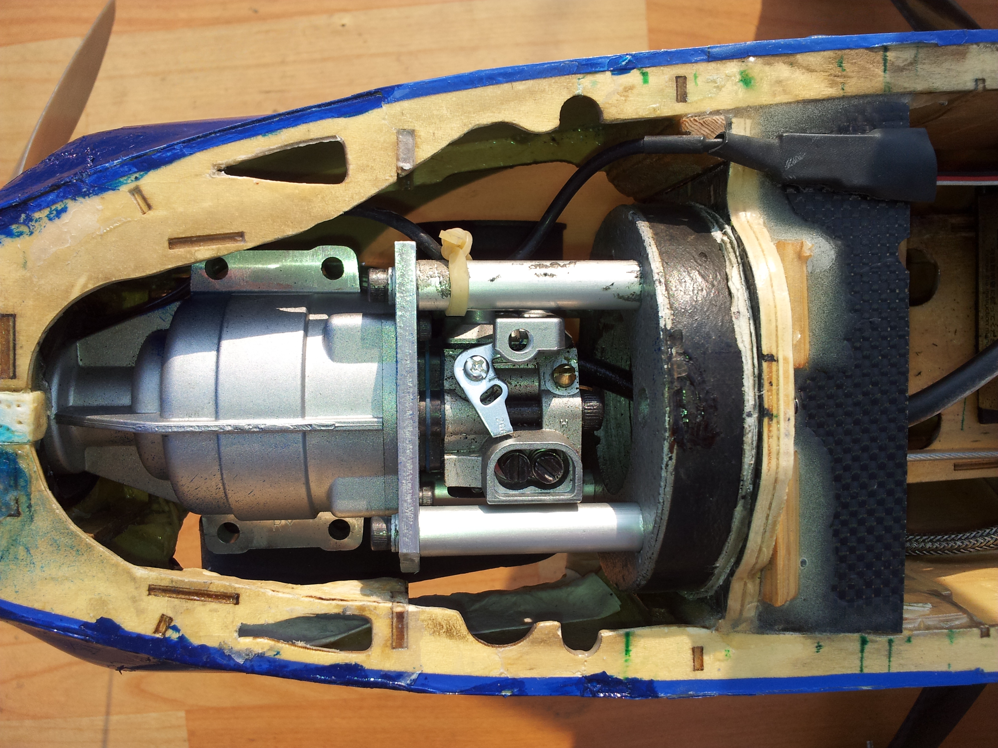
From Picture this GT22 is modified to stand-off to original Hyde mound, which I bought from Central hobbies two years ago.
It is not easy to install in a limited space of engine bay in Wind S 110, so I tightened each part, engine, stand-off, mount, in the engine bay, and muffler from outside.
To modify to rail to stand-off mount, an aluminum plate (8x8x4 mm, I do not remember exactly now) was placed between crank case and carburettor tightened with four M3 bolts (14 mm), 4 mm longer than original M3 bolts (10 mm).
I hope someone follow my mod Wind S 110.
Regards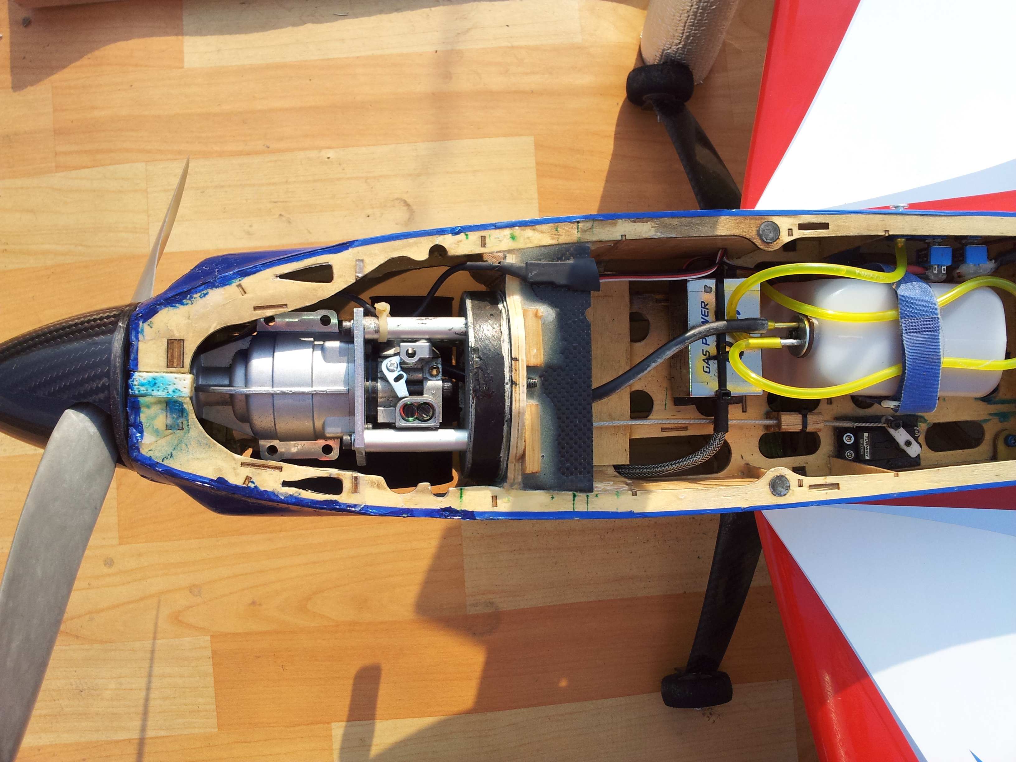
My both gasified planes are equipped with OS stock muffler which are really a muffler, very quiet, quieter than YS stock mufflers, IMO.
Sebart's Wind S 110 is quite large plane, but not heavier than most gas-powerd 110-sized plane. I have not weighed it (4,295 g), but OS GT 22 is enough for this plane, unlimited flying high.
APC 16x10 prop is installed, compared to APC 19x10 on OS GT33 on the vaquish.
This gasified Wind S 110 is now flown more than 20 flights already.
From Picture this GT22 is modified to stand-off to original Hyde mound, which I bought from Central hobbies two years ago.
It is not easy to install in a limited space of engine bay in Wind S 110, so I tightened each part, engine, stand-off, mount, in the engine bay, and muffler from outside.
To modify to rail to stand-off mount, an aluminum plate (8x8x4 mm, I do not remember exactly now) was placed between crank case and carburettor tightened with four M3 bolts (14 mm), 4 mm longer than original M3 bolts (10 mm).
I hope someone follow my mod Wind S 110.
Regards
Last edited by choihjin; 12-02-2013 at 01:20 PM. Reason: Weight measured