


Audax F3A - new project for 2013


 03-01-2015, 11:17 AM
#80

Thread Starter
The plan is to use Robart pin hinges and make the rudder removable, so the rudder leading edge is rounded and will be partially hidden inside the fuselage. I also built a second jig to help me attach the balsa sheeting and checked its alignment with the rudder structure.


03-04-2015, 04:38 AM
#81
Thread Starter
Next step was detaching the rudder structure from the jig, cleaning and sanding the ribs where they were joined with the jig and add the balsa sheeting (only on the right side for now):


03-06-2015, 05:09 AM
#82
Thread Starter
I added the balsa blocks to support the pin hinges for their entire length and, using the lasercut holes in the front spar as a guide, i drilled the holes in the balsa blocks. The block at the bottom will also support the control horns, so it is a bit larger.
I used only 1.5mm balsa for the skins, but now that it's sheeted on both sides, the rudder seems very strong. When pressing the rudder between the 2 jigs i used a lot of weight, so i had to protect the balsa skins with a piece of cardboard. The balsa skins were a little oversized, so in the end i sanded them flush with the edges of the rudder.


I used only 1.5mm balsa for the skins, but now that it's sheeted on both sides, the rudder seems very strong. When pressing the rudder between the 2 jigs i used a lot of weight, so i had to protect the balsa skins with a piece of cardboard. The balsa skins were a little oversized, so in the end i sanded them flush with the edges of the rudder.
Last edited by Alex Voicu; 03-06-2015 at 05:18 AM.
03-08-2015, 01:12 AM
#83
Thread Starter
I wrapped a wet sheet of 1.5mm balsa around the wing tube, let it dry overnight and used it for sheeting the rounded leading edge. The balsa block at the bottom of the rudder has a 1.5mm plywood core with 2 tabs that will fit into the bottom rib slots to ensure the proper positioning and alignment. The plywood core also has slots for the tailwheel steering pin and the hinge axle. The balsa block was sanded to shape and in the end i added some light filler around the joints. The rudder is now done and i'll move on to the stabs.


03-12-2015, 09:41 AM
#84
Thread Starter
I started working on the stabs by preparing the ribs supporting the servo and incidence adjuster. To make sure these will be secured properly, i added small pieces of 1.5mm plywood to reinforce the liteply locally. I drilled the holes and temporarily attached the adjuster and servo using wood screws.


Baking paper is used to keep the stab jig from sticking to the building board. CA glue doesn’t penetrate the baking paper, and the jig is attached to the board using pins. There’s no need for printed drawings to assemble the structure; all i had to do was tracing 2 perpendicular lines on the paper, align the first 2 members of the jig with these lines and everything else is self-aligning.


I didn’t want to rely entirely on the ribs to achieve the proper curvature of the leading edges, so during design stage i also added a horizontal former which will help bending the leading edge with improved accuracy and perfect symmetry between the 2 stabs.


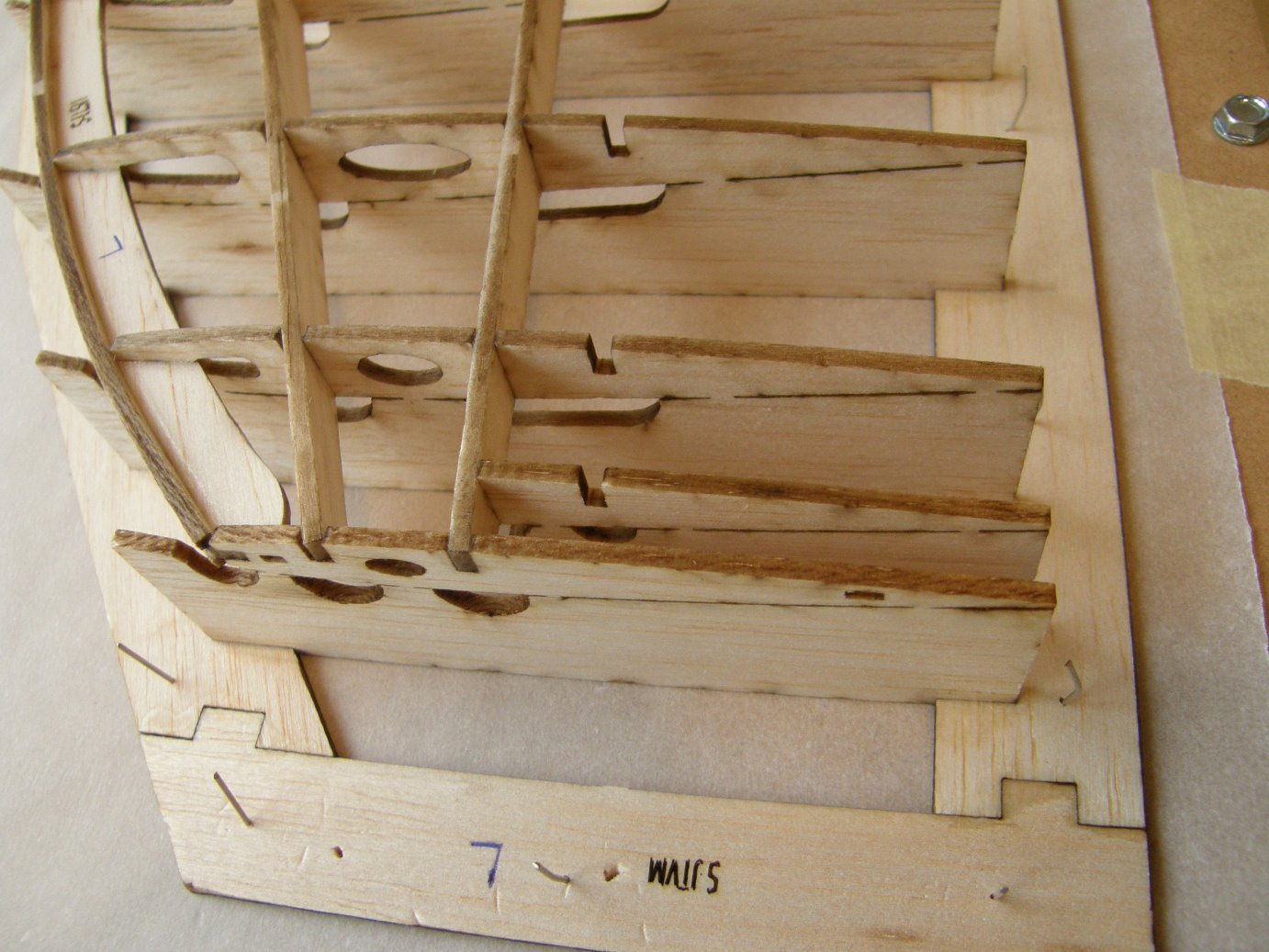
To make the stab structure easy to detach from the jig, the ribs are attached to their supports only in a few points. To prevent any glue running from the joints to accidentally flow into the small spaces between the ribs and their supports (thus making the structure difficult to detach from the jig), all rib supports have semi-circular or oval cut-outs situated directly below the joints. I hope the picture below explains this better:

A few more pictures showing the assembly process:


Baking paper is used to keep the stab jig from sticking to the building board. CA glue doesn’t penetrate the baking paper, and the jig is attached to the board using pins. There’s no need for printed drawings to assemble the structure; all i had to do was tracing 2 perpendicular lines on the paper, align the first 2 members of the jig with these lines and everything else is self-aligning.
I didn’t want to rely entirely on the ribs to achieve the proper curvature of the leading edges, so during design stage i also added a horizontal former which will help bending the leading edge with improved accuracy and perfect symmetry between the 2 stabs.
To make the stab structure easy to detach from the jig, the ribs are attached to their supports only in a few points. To prevent any glue running from the joints to accidentally flow into the small spaces between the ribs and their supports (thus making the structure difficult to detach from the jig), all rib supports have semi-circular or oval cut-outs situated directly below the joints. I hope the picture below explains this better:
A few more pictures showing the assembly process:
Last edited by Alex Voicu; 03-12-2015 at 09:45 AM.
03-17-2015, 09:33 AM
#85
Thread Starter
Adding the rib doublers:


Finished stab structure:


Adding the fiberglass sleeve:

Detaching the stab structure from the jig:


Sanding the leading edge following the airfoil shape:

Preparing the upper surface skin, using 2mm balsa:

Attaching the upper surface skin to the stab structure:


Sheeted stab structure (only upper surface for now):


Finished stab structure:
Adding the fiberglass sleeve:
Detaching the stab structure from the jig:
Sanding the leading edge following the airfoil shape:
Preparing the upper surface skin, using 2mm balsa:
Attaching the upper surface skin to the stab structure:
Sheeted stab structure (only upper surface for now):
03-21-2015, 09:31 AM
#86
Thread Starter
Adding the balsa block for the control horn and the wood block for the stab retaining screw:


Sheeting the stab lower surface:


Adding the trailing edge:


Sheeting the stab lower surface:
Adding the trailing edge:
03-25-2015, 08:37 AM
#87
Thread Starter
The 6mm balsa leading edges are quite stiff and it would be very difficult to bend them following the shape of the stab. I had to soak them with hot water (which makes them a lot more flexible) and let them dry overnight in a curved position.


It was now quite easy to attach them to the stabs:

To shape the leading edges accurately, i improvised a tool to help me mark the centerlines on the balsa strips. By shimming it with tape at the bottom and lightly sanding it at the top, i calibrated its height to leave a mark precisely at the centerlines of the root and tip ribs.


After some careful sanding, the result looks like this:


Assembling the stab tip blocks and attaching them to the stabs:


Shaping the stab tips:


Progress on the stab so far:


It was now quite easy to attach them to the stabs:
To shape the leading edges accurately, i improvised a tool to help me mark the centerlines on the balsa strips. By shimming it with tape at the bottom and lightly sanding it at the top, i calibrated its height to leave a mark precisely at the centerlines of the root and tip ribs.
After some careful sanding, the result looks like this:
Assembling the stab tip blocks and attaching them to the stabs:
Shaping the stab tips:
Progress on the stab so far:
Last edited by Alex Voicu; 03-25-2015 at 08:49 AM.
03-29-2015, 07:07 AM
#88
Thread Starter
Separating the elevators:


Preparing the balsa hinge lines:


Attaching and sanding the hinge lines:


Attaching the stab root balsa block. This will be sanded later to fit the fuselage:


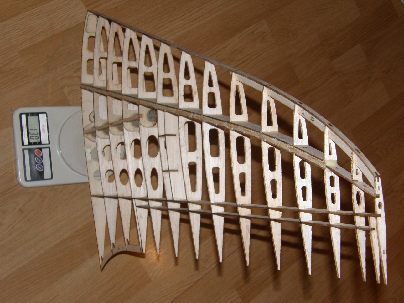
Weight and progress on the stabs so far:


Preparing the balsa hinge lines:
Attaching and sanding the hinge lines:
Attaching the stab root balsa block. This will be sanded later to fit the fuselage:
Weight and progress on the stabs so far:
04-03-2015, 08:52 AM
#89
Thread Starter
With the stabs almost done it's now time to move on to the wing assembly.
All the wing ribs are made of 2.5mm balsa with the exception of the root rib which is made of 3mm liteply. The ribs supporting the wingtube have 1.5mm plywood doublers to reinforce the balsa locally near the wingtube holes and also to connect the 2 spars. This helps transmitting the loads from the main spar to the carbon tube and distributes the loads more evenly through the structure. The root rib also has a blind nut for the wing retaining screw and a doubler near the leading edge where the incidence adjuster will be placed.
The first step was preparing the first 5 ribs by adding the plywood doublers, blind nut and also slightly sanding the wingtube holes to match the diameter of the sleeve.


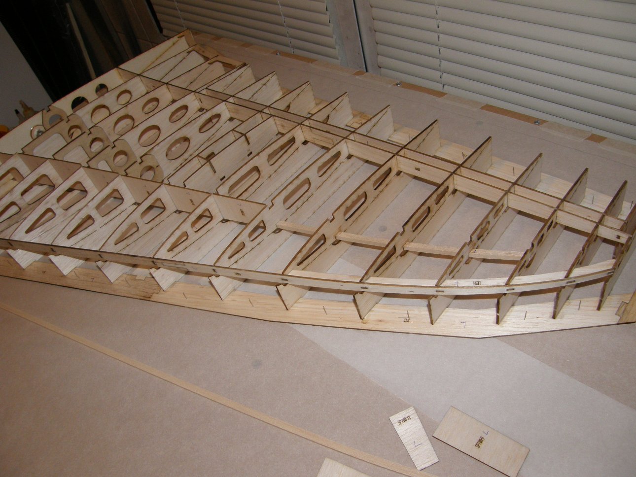
The jig assembly starts at the trailing edge which is made of 2 parts so i had to make sure it is perfectly straight.

I also had to check the perpendicularity of the member near the root rib. Together with the trailing edge, it will define the alignment of all the other parts, so it is important to make these 2 perfectly straight and perpendicular to each other:

All the other parts are self aligning:


Adding the ribs:


All the wing ribs are made of 2.5mm balsa with the exception of the root rib which is made of 3mm liteply. The ribs supporting the wingtube have 1.5mm plywood doublers to reinforce the balsa locally near the wingtube holes and also to connect the 2 spars. This helps transmitting the loads from the main spar to the carbon tube and distributes the loads more evenly through the structure. The root rib also has a blind nut for the wing retaining screw and a doubler near the leading edge where the incidence adjuster will be placed.
The first step was preparing the first 5 ribs by adding the plywood doublers, blind nut and also slightly sanding the wingtube holes to match the diameter of the sleeve.
The jig assembly starts at the trailing edge which is made of 2 parts so i had to make sure it is perfectly straight.
I also had to check the perpendicularity of the member near the root rib. Together with the trailing edge, it will define the alignment of all the other parts, so it is important to make these 2 perfectly straight and perpendicular to each other:
All the other parts are self aligning:
Adding the ribs:
04-09-2015, 10:50 AM
#90
Thread Starter
More work on the wing assembly:


Adding the curved trailing edge:


Adding the aileron end ribs and hinge line former:


Adding the leading edge formers:


Assembling the servo box:

Progress on the wing so far:


Adding the curved trailing edge:
Adding the aileron end ribs and hinge line former:
Adding the leading edge formers:
Assembling the servo box:
Progress on the wing so far:
04-18-2015, 06:12 AM
#91
Thread Starter
Bending the 6x6mm balsa stringers with water:

I used the shear webs to determine the correct position and distance between ribs along the spar:
Attaching the main spar balsa stringers:

The ribs near the tip of the wing are too thin for the 6x6mm balsa stringers, so i replaced them with a balsa former:

Adding the 6x6mm balsa stringers for the wingtube spar:

Adding the wingtube sleeve:

Adding the shear web:


Completed left wing structure:


I used the shear webs to determine the correct position and distance between ribs along the spar:
Attaching the main spar balsa stringers:
The ribs near the tip of the wing are too thin for the 6x6mm balsa stringers, so i replaced them with a balsa former:
Adding the 6x6mm balsa stringers for the wingtube spar:
Adding the wingtube sleeve:
Adding the shear web:
Completed left wing structure:
 04-18-2015, 01:19 PM
#93
Thread Starter
Thank you Alejandro! Unfortunately i'm not going to the WC this year, but who knows, maybe someday i will.
Good luck and have a great time in Switzerland!
Good luck and have a great time in Switzerland!
04-27-2015, 02:13 AM
#95
Thread Starter
Wing structure detached from the jig:
Sanding the leading edge former following the shape of the airfoil:

Sanding the excess glue from the shear webs:

Preparing the wing skin:

Wing structure and skin attached using polyurethane adhesive and pressed together in the jig:

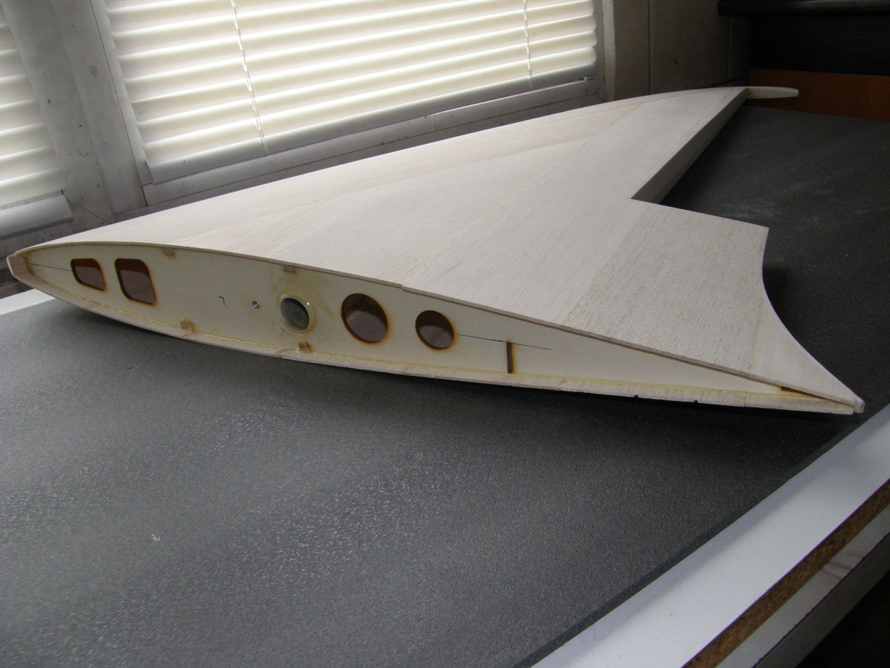
A few images of the result:


Sanding the leading edge former following the shape of the airfoil:
Sanding the excess glue from the shear webs:
Preparing the wing skin:
Wing structure and skin attached using polyurethane adhesive and pressed together in the jig:
A few images of the result:
05-02-2015, 04:07 AM
#97
Thread Starter
Thank you Alejandro!
Adding the balsa block for the control horn:

Wing structure and the second skin panel attached using polyurethane adhesive and pressed together in the jig:


Sanding off the excess sheeting at the leading edge:


Bending the 10mm balsa leading edges with hot water:

Attaching the leading edges to the wing:

Rough shaping of the leading edges:

Marking the leading edge centerline:


Sanding the leading edges:


Adding the balsa block for the control horn:
Wing structure and the second skin panel attached using polyurethane adhesive and pressed together in the jig:
Sanding off the excess sheeting at the leading edge:
Bending the 10mm balsa leading edges with hot water:
Attaching the leading edges to the wing:
Rough shaping of the leading edges:
Marking the leading edge centerline:
Sanding the leading edges:
05-08-2015, 07:25 AM
#98
Thread Starter
Sanding the excess sheeting at the trailing edge:

Attaching and sanding the trailing edge balsa strips:


Preparing and attaching the wing tips:


Rough shaping and sanding the wingtips:


Attaching and sanding the trailing edge balsa strips:
Preparing and attaching the wing tips:
Rough shaping and sanding the wingtips:
05-15-2015, 10:47 AM
#100
Thread Starter
Marking and cutting the ailerons:


Adding and sanding the balsa blocks at the root and tip of the aileron:


Preparing the hinge lines:


Attaching the aileron hinge line:

Hinge line attached to the wing and sanded:

Sanding the excess balsa sheeting at the wing root:

Adding the wing root balsa block:


Adding and sanding the balsa blocks at the root and tip of the aileron:
Preparing the hinge lines:
Attaching the aileron hinge line:
Hinge line attached to the wing and sanded:
Sanding the excess balsa sheeting at the wing root:
Adding the wing root balsa block: