


Audax F3A - new project for 2013

 05-27-2015, 11:30 PM
#103

Thread Starter
The stab tube sleeve was attached to the fuselage with epoxy and microbaloons. The stab key is made of 4mm diameter aluminium and passes through a carbon tube glued inside the fuselage so it can be replaced if necessary.


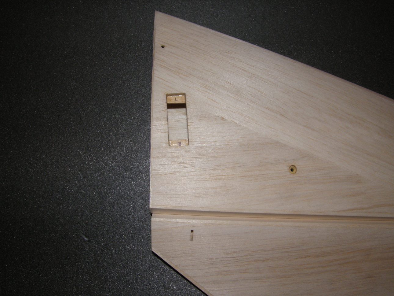
The wing tube sleeve attached to the fuselage:


Wing and stab root blocks sanded to fit the fuselage:


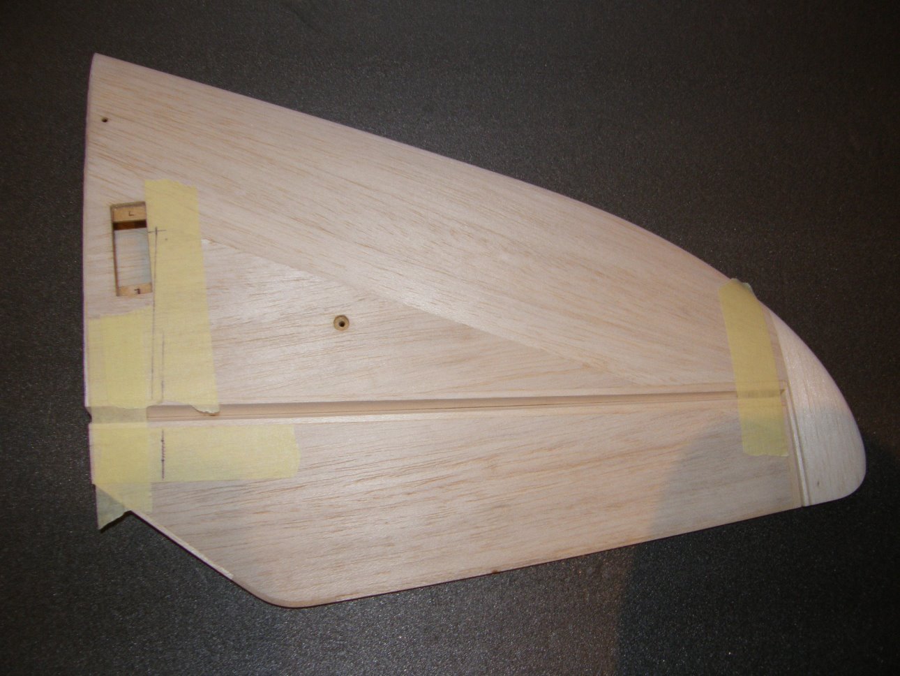
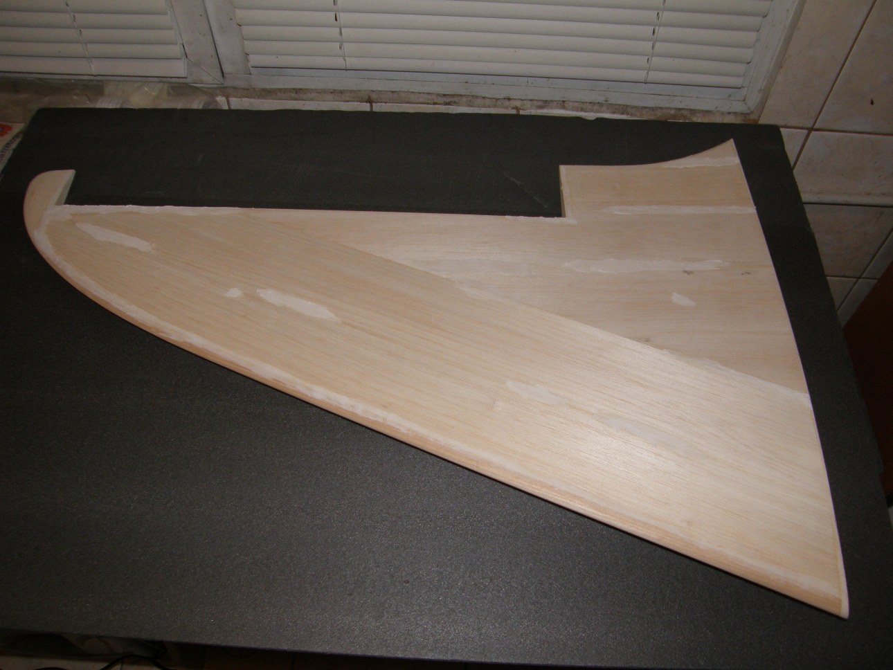
A few images of the finished wing:


The wing tube sleeve attached to the fuselage:
Wing and stab root blocks sanded to fit the fuselage:
A few images of the finished wing:
06-05-2015, 11:10 AM
#104
Thread Starter
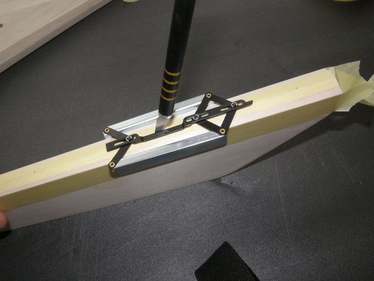
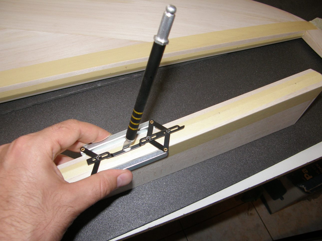
Installing the wing incidence adjusters:


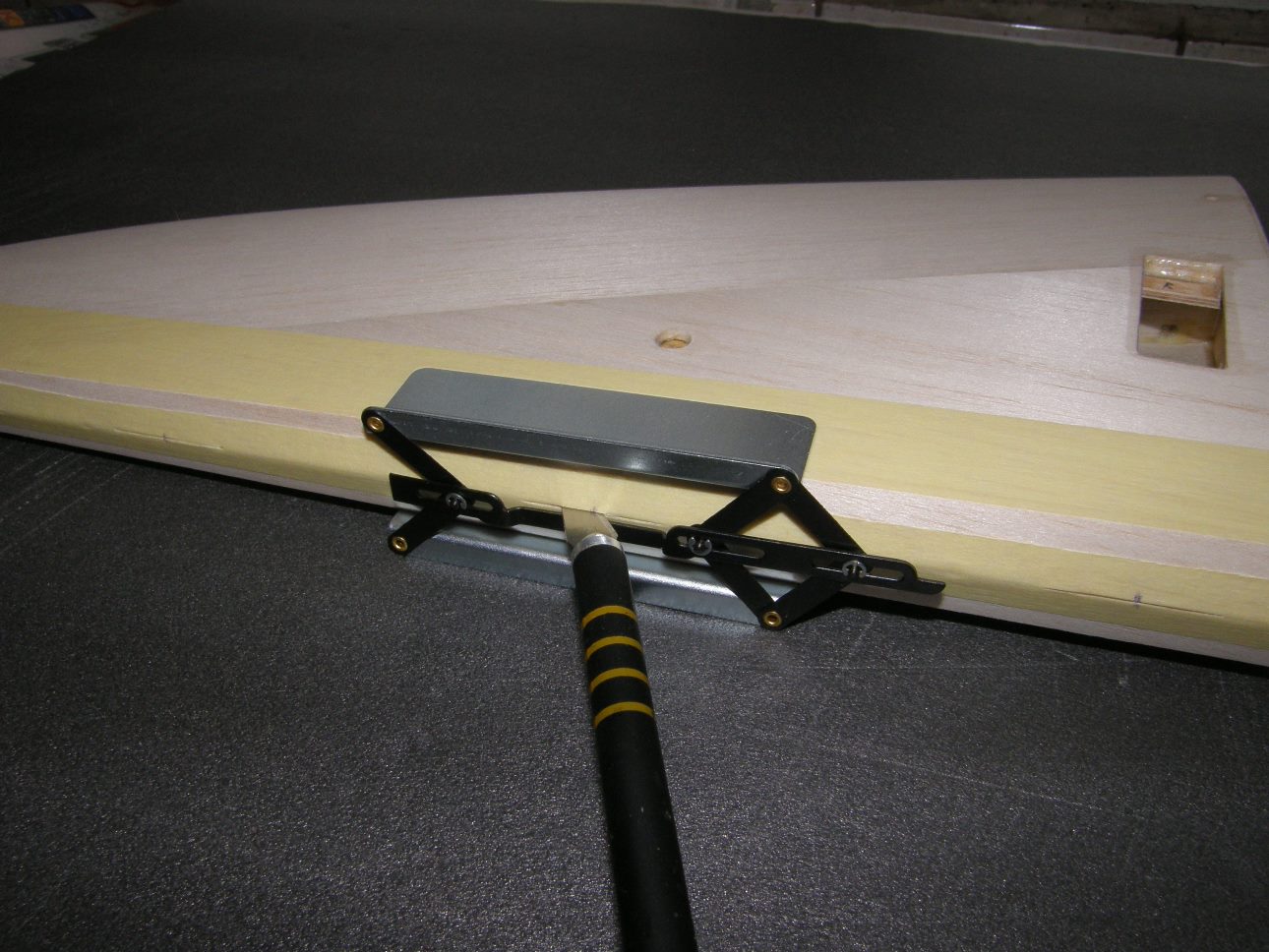
Marking and drilling the adjuster holes into the wing root rib:


Wings fitted:


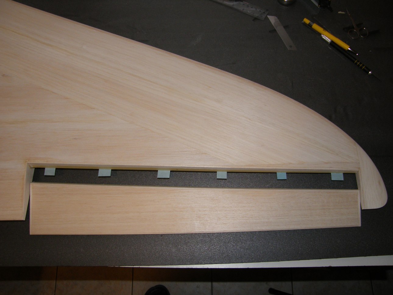
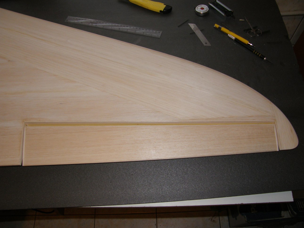
Cutting the aileron servo slots:


Marking and drilling the adjuster holes into the wing root rib:
Wings fitted:
Cutting the aileron servo slots:
06-12-2015, 11:06 AM
#106
Thread Starter
After some thinking i decided to give up on the idea of having the elevator servos hidden inside the stabs. The thickness of the nut, servo arm, spacer, ball link and the screw head are all adding up, so the slot required for the free movement of the linkage would be very wide. For me this defeats the purpose of having the servo hidden inside the stabs.
The other alternative would be to use a very long servo arm and small servo travels so the ball link doesn't interfere with the stab underside, but i didn't want to sacrifice servo resolution.
I decided to install the servos on the stab undersurface so i had to improvise something for the servo mounts. Too bad i didn't think this through from the start because it would save a lot of weight, probably around 15g for each stab.
06-19-2015, 10:46 PM
#107
Thread Starter
Marking the location and cutting the slot for the elevator control horn:
Hinging the elevators:

Adding some light filler on the stab surfaces:
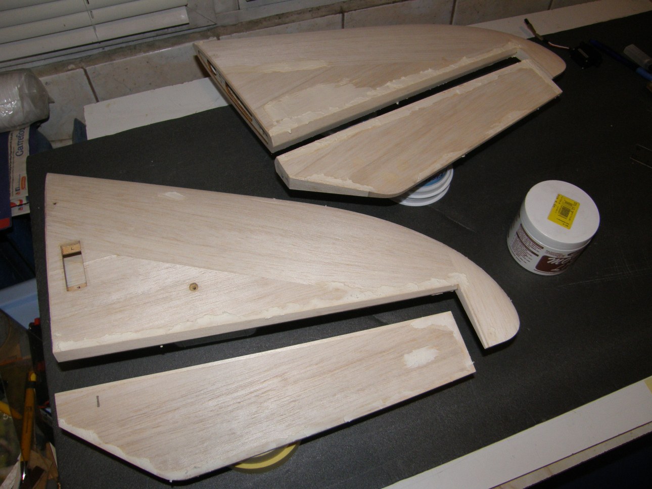
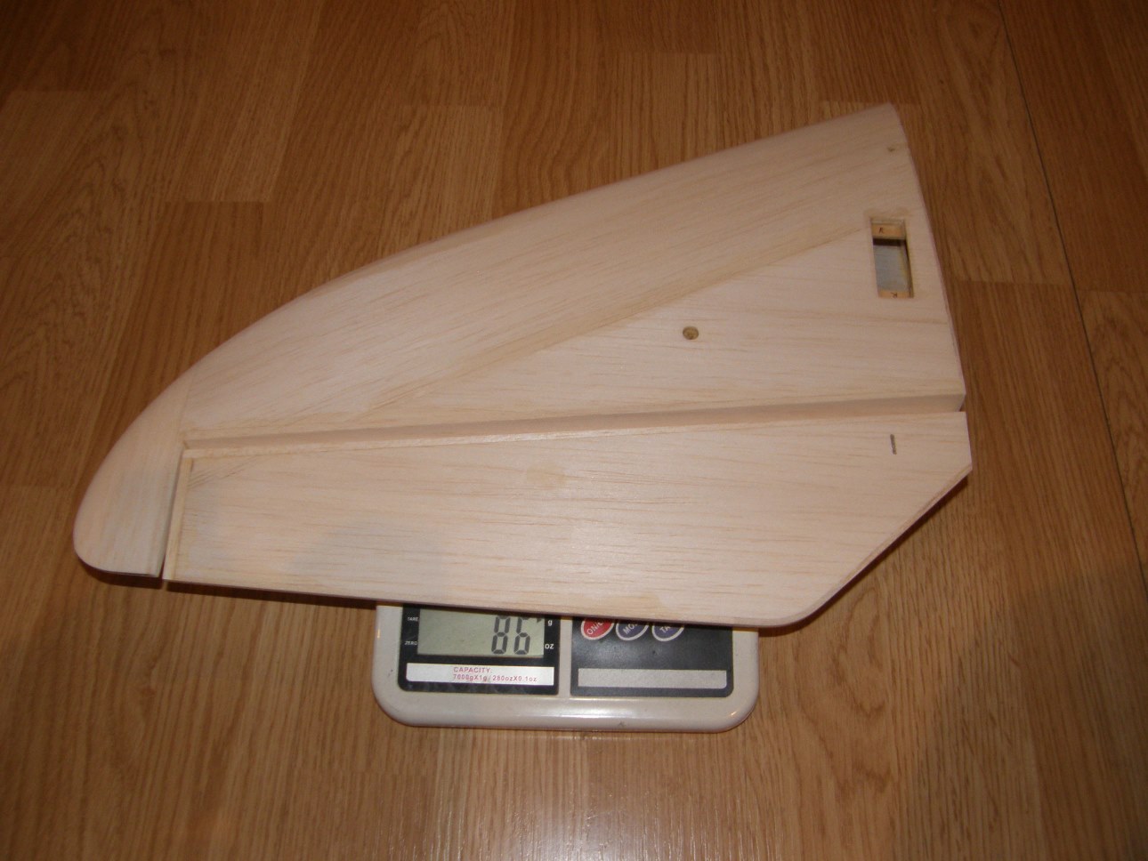
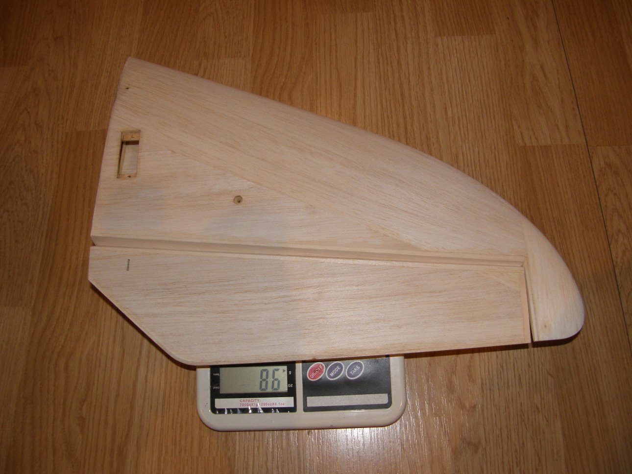
Filler sanded off, final stab weights before covering:
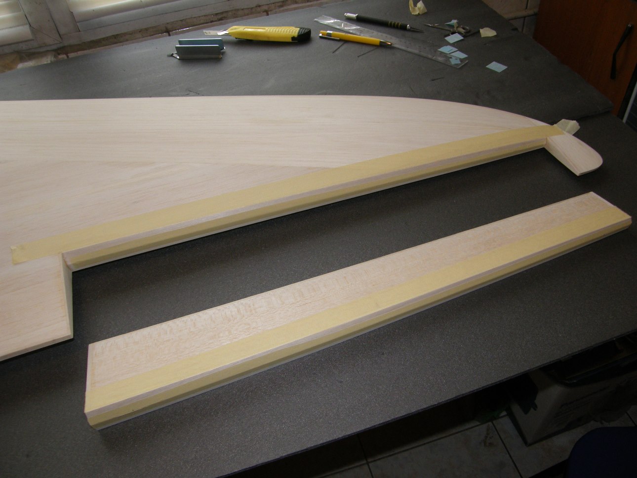
Hinging the ailerons:
Adding light filler to the wing surfaces:
Filler sanded off, final wing weights before covering:
Hinging the elevators:
Adding some light filler on the stab surfaces:
Filler sanded off, final stab weights before covering:
Hinging the ailerons:
Adding light filler to the wing surfaces:
Filler sanded off, final wing weights before covering:
06-20-2015, 11:39 PM
#108
Thread Starter
Before film covering, i assembled the model and took a few pictures. I'm not sure the pictures can reveal the size of this thing, so here are a few dimensions of the model. The wing root chord is 580mm which i believe is larger than anything out there at the moment. The fuselage is quite tall at approx. 380mm in the the canopy area and the fin is 455 mm tall. In general it seems huge and i barely had enough space for assembly.


Last edited by Alex Voicu; 06-20-2015 at 11:41 PM.
07-18-2015, 01:44 AM
#116
Thread Starter
Thanks Brian. The bottom color scheme was quickly improvised taking inspiration from other models and using 2 high contrast colors from the top side.
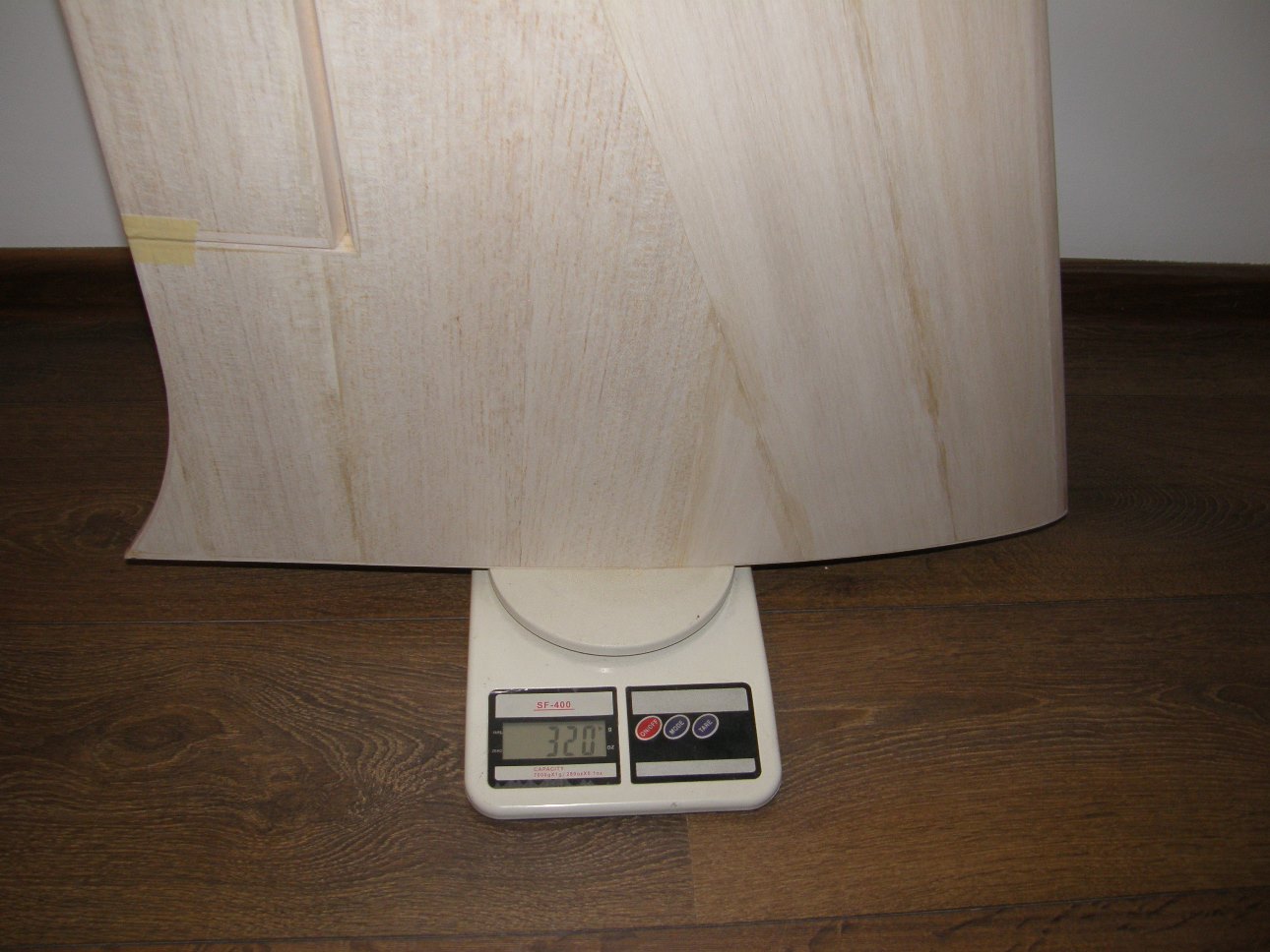
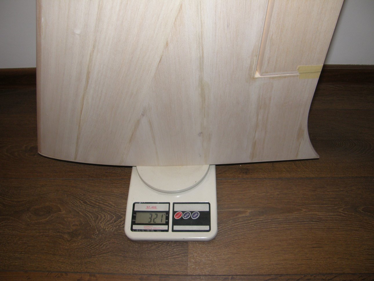
I attached a few images of the wing film covering process. Weight after film covering is 370g for the left wing and 372g for the right wing.


I attached a few images of the wing film covering process. Weight after film covering is 370g for the left wing and 372g for the right wing.
08-17-2015, 11:28 PM
#118
Thread Starter
The fin post was traced and cut from 10mm balsa, with additional doublers to support the pin hinges:


Fortunately i lasercut 2 rudder spars, so i used the spare one as a guide for drilling the hinge holes. The hinges were attached using high strength epoxy and microballoons, making sure they are 90 degrees to the fin post centerline:


The rudder will be detachable, so i used a carbon rod going through all hinges to save weight. This was joined with a steel rod bent at 90 degrees at the base of the rudder:


The fin post was finally glued inside the fuselage.The slow curing epoxy gave me enough time to check the proper alignment and free movement of the rudder:


The fin post hinges were reinforced with small plywood triangles:

Fortunately i lasercut 2 rudder spars, so i used the spare one as a guide for drilling the hinge holes. The hinges were attached using high strength epoxy and microballoons, making sure they are 90 degrees to the fin post centerline:
The rudder will be detachable, so i used a carbon rod going through all hinges to save weight. This was joined with a steel rod bent at 90 degrees at the base of the rudder:
The fin post was finally glued inside the fuselage.The slow curing epoxy gave me enough time to check the proper alignment and free movement of the rudder:
The fin post hinges were reinforced with small plywood triangles:
 08-28-2015, 07:41 AM
#121
Thread Starter
Yes, the tips are narrow, but after looking at the CPLR's model from the 2015 World Championships, i think it's going to be fine

Last edited by Alex Voicu; 08-28-2015 at 08:16 AM.
09-04-2015, 11:01 AM
#122
Thread Starter
Today's update shows the electric motor installation. The motor is a Himax 6330 Pro, using the front mounting conversion kit from F3A Unlimited:


I plan to test the 0 degrees right thrust setup (as used on the Allure), but it will be possible to adjust the thrust line by shimming the motor mount.
I used a glassfiber plate to trace the 82mm spinner diameter on the fuselage. The position of the plate was carefully adjusted until it was perpendicular on the fuselage center line. For now, the nose was actually cut 4mm longer to compensate for any thrust line adjustments.


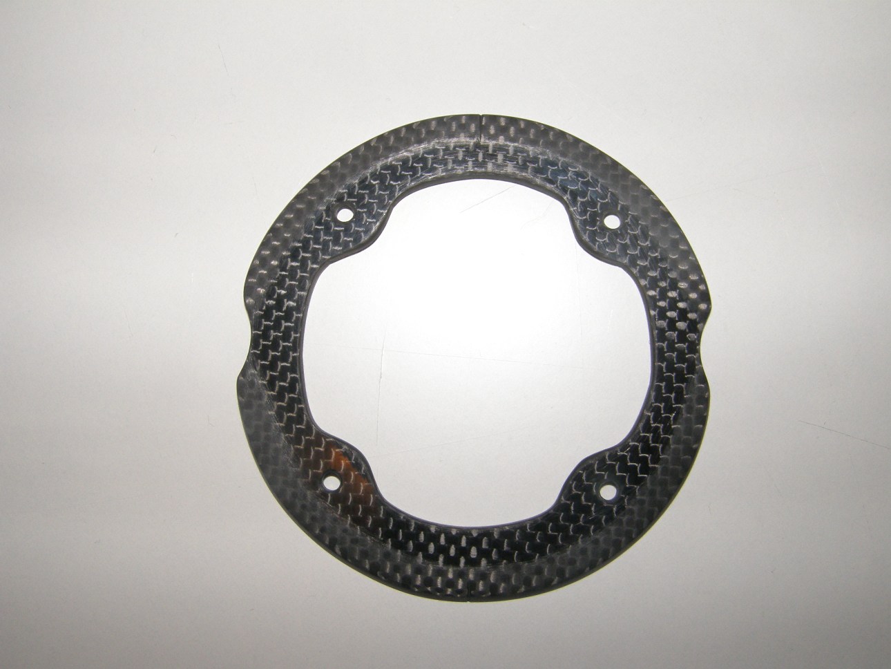
Cutting the X mount from 2.5mm carbon plate and the nose ring template from 2.5mm plywood:


Cutting the final nose ring from 2.5mm carbon and preparing the surface for bonding:

Assembling the motor mount:


1mm spacer ring taped to the spinner backplate:

Tacking the nose ring in place with CA:


Nose ring final bonding, using high strength epoxy and carbon rovings:


Rear support structure (2mm glass fiber):


I plan to test the 0 degrees right thrust setup (as used on the Allure), but it will be possible to adjust the thrust line by shimming the motor mount.
I used a glassfiber plate to trace the 82mm spinner diameter on the fuselage. The position of the plate was carefully adjusted until it was perpendicular on the fuselage center line. For now, the nose was actually cut 4mm longer to compensate for any thrust line adjustments.
Cutting the X mount from 2.5mm carbon plate and the nose ring template from 2.5mm plywood:
Cutting the final nose ring from 2.5mm carbon and preparing the surface for bonding:
Assembling the motor mount:
1mm spacer ring taped to the spinner backplate:
Tacking the nose ring in place with CA:
Nose ring final bonding, using high strength epoxy and carbon rovings:
Rear support structure (2mm glass fiber):
Last edited by Alex Voicu; 09-04-2015 at 11:19 AM.
09-13-2015, 11:15 PM
#123
Thread Starter
Installing the hinges and sealing the aileron / elevator hinge lines with transparent oracover film:


Cutting and installing the control horns:


Control linkage:


Pull-pull cable exit holes were drilled, a small segment of bowden tube was attached with epoxy and sanded flush with the fuselage:


Cooling intake holes were cut under the nose. The side intakes were left for later because their position depends on the motor right thrust angle.


Adding the air deflector for motor cooling and the ESC support:


Cutting the vent hole on the bottom of the fuselage and holes for the aileron/ elevator servo leads:


Cutting and installing the control horns:
Control linkage:
Pull-pull cable exit holes were drilled, a small segment of bowden tube was attached with epoxy and sanded flush with the fuselage:
Cooling intake holes were cut under the nose. The side intakes were left for later because their position depends on the motor right thrust angle.
Adding the air deflector for motor cooling and the ESC support:
Cutting the vent hole on the bottom of the fuselage and holes for the aileron/ elevator servo leads:
09-27-2015, 11:46 PM
#125
Thread Starter
Thanks Bill
I've been working on the rudder pull-pull system. The wires are crossed inside the fuselage so i had to study the geometry of the pull-pull system to make sure there's equal tension in the wires at all rudder deflections. I also had to consider that the wires exit the fuselage through the small bowden tubes (representing 2 fixed points). I determined that a 3mm offset was needed on the servo arm (distance between servo wheel center and wires attaching points). I used 2.5mm carbon plate for the servo arm.


I've been working on the rudder pull-pull system. The wires are crossed inside the fuselage so i had to study the geometry of the pull-pull system to make sure there's equal tension in the wires at all rudder deflections. I also had to consider that the wires exit the fuselage through the small bowden tubes (representing 2 fixed points). I determined that a 3mm offset was needed on the servo arm (distance between servo wheel center and wires attaching points). I used 2.5mm carbon plate for the servo arm.
Last edited by Alex Voicu; 09-27-2015 at 11:52 PM.