


Airflow visualisation
 10-16-2013, 03:45 PM
#101
Senior Member
My Feedback: (2)

Join Date: Nov 2002
Location: Jackson, MI
Posts: 2,102
Likes: 0
Received 0 Likes
on
0 Posts
Interesting tests, Alex. Keep it up!
Talking about the Corsair photo
I can assure you that P-factor, gyro-P and torque are all at play in straight & level flight at all speeds. Any tri-gear (nosedragger) prop plane, single or multi-engine, Cessna 150 to P-63 to King Air 350 twin turboprop, will turn hard left if right rudder is not applied at takeoff. The Cessna 421 I fly will not stay on the runway if full power is rapidly applied, even with full right rudder, or if powered up with brakes on, and then released. For that reason, we slowly add power for 5-8 seconds while rolling to give the rudder more authority after 40 knots or so. Same thing in descents, we must use left rudder to correct for P-factor with the nose low.
The Corsair was one of the fighters that was powerful enough to roll over on the ground if power was abruptly applied, and this killed more than one Naval/Marine aviator.
Talking about the Corsair photo
You are correct to point out the rudder.
However 'p-factor and gyroscopic precession' are NOT in play. So the point you make re the rudder is even more valid re 'SSS'.
The p-factor and gyroscopic precession only come into play during pitch and or yaw changes.
The torque is in play but that is transferring into the deck via the UC.
However 'p-factor and gyroscopic precession' are NOT in play. So the point you make re the rudder is even more valid re 'SSS'.
The p-factor and gyroscopic precession only come into play during pitch and or yaw changes.
The torque is in play but that is transferring into the deck via the UC.
The Corsair was one of the fighters that was powerful enough to roll over on the ground if power was abruptly applied, and this killed more than one Naval/Marine aviator.

 10-17-2013, 07:44 AM
#103

Join Date: Apr 2010
Location: Richmond, CA
Posts: 169
Likes: 0
Received 0 Likes
on
0 Posts
10-18-2013, 08:10 AM
#104
My Feedback: (1)

Join Date: Dec 2002
Location: Quartz Hill,
CA
Posts: 71
Likes: 0
Received 0 Likes
on
0 Posts
There are a lot of things at play that cause a plane to want right thrust:
-spiraling air stream
-torque
-gyroscopic effect
-p-factor
The contra planes combat almost the whole list.
The props with less area at the hub would have less P-factor effect, since the portion of the prop with the highest pitch is eliminated.
Whoever said spiraling air 'doesn't exist' is likely a Republican Scientist who moved to aerodynamics after disproving climate change.
Hey Joe, I corrected your misstatement:
Whoever said spiraling air 'doesn't exist' is likely a Liberal Environmentalist who moved to aerodynamics after falsifying climate change data.
No self-serving Republican would ever claim that Spin doesn't exist...

Thx, Jerry
10-18-2013, 02:56 PM
#105

My Feedback: (2)

Join Date: Feb 2003
Location: Palm Bay, FL
Posts: 1,046
Likes: 0
Received 0 Likes
on
0 Posts
Great job, Alex and mythrandir!!!
Hopefully, your data will be used in the next generation of pattern ship.
It's interesting to note that this is a subject well pondered:
http://www.rcuniverse.com/forum/elec...p-winglet.html
Hopefully, your data will be used in the next generation of pattern ship.
It's interesting to note that this is a subject well pondered:
http://www.rcuniverse.com/forum/elec...p-winglet.html
10-28-2013, 10:12 AM
#106
Thread Starter
This weekend i made more progress with the setup on my plane and eliminated the proverse roll coupling i mentioned earlier.
I always felt that the stab was placed too high on my Radiance prototype, forcing me to use high incidence (+1.1 deg) on the wing to counter the pull to canopy on the vertical uplines. This was fixed on the kit version, but it remained unchanged on my prototype for 3 years. With the competition season now over, i had plenty of time to work on the plane so i moved the stab 30mm lower and changed the wing incidence to +0.7deg, as Bryan recommended. This improved many aspects: the upline pull to canopy disappeared, knife edge roll coupling was gone too, downline mix slightly reduced.
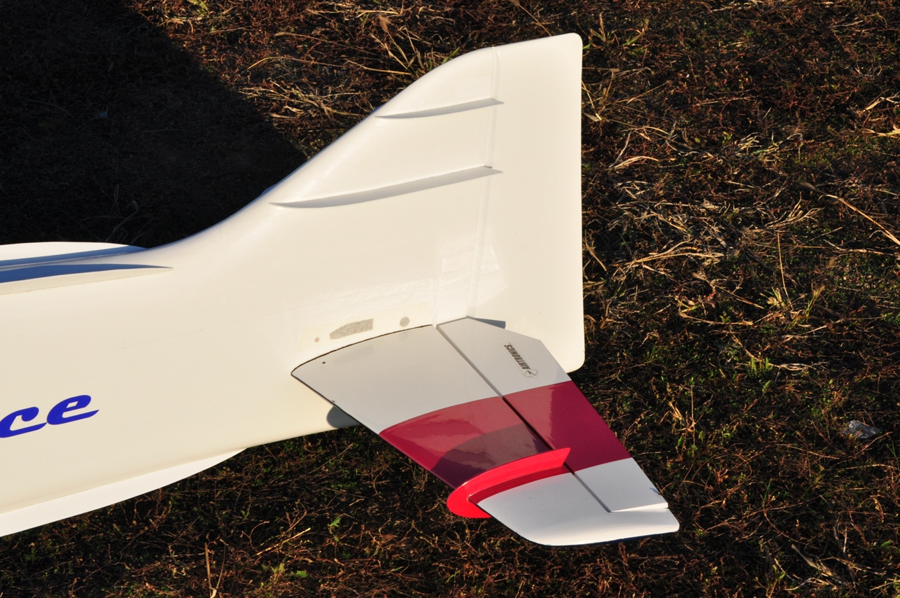
Just to test the improvements in KE performance brought by the fuselage strakes and fin fences, i went through the first few P13 maneuvers (half clover leaf, stall turn, roll combination, half square loop, triangle and split S), all performed in knife edge position. The corners seemed to be as tight as when performed in normal position and i never used full rudder throw. Of course, the maneuvers didn't look as smooth and precise because it's quite unusual for me to perform them on KE, but there's enough rudder power and fuselage lift to go through the maneuvers, no doubt about that.
I always felt that the stab was placed too high on my Radiance prototype, forcing me to use high incidence (+1.1 deg) on the wing to counter the pull to canopy on the vertical uplines. This was fixed on the kit version, but it remained unchanged on my prototype for 3 years. With the competition season now over, i had plenty of time to work on the plane so i moved the stab 30mm lower and changed the wing incidence to +0.7deg, as Bryan recommended. This improved many aspects: the upline pull to canopy disappeared, knife edge roll coupling was gone too, downline mix slightly reduced.
Just to test the improvements in KE performance brought by the fuselage strakes and fin fences, i went through the first few P13 maneuvers (half clover leaf, stall turn, roll combination, half square loop, triangle and split S), all performed in knife edge position. The corners seemed to be as tight as when performed in normal position and i never used full rudder throw. Of course, the maneuvers didn't look as smooth and precise because it's quite unusual for me to perform them on KE, but there's enough rudder power and fuselage lift to go through the maneuvers, no doubt about that.
10-28-2013, 01:41 PM
#107
Glad to Help Alex
This goes to show how the wings will effect the aiplane trim on every aspect of flying up lines ,Down lines ,and knife edge flight.
On my trim chart I say "CG will effect every aspect of the trim and design fuction" The little things get by us sometimes like, roll coupling ect. the more you demand from the plane the more a poorly trimed airplane will let you down.
This also works in reverse, when the inc. is to little and the C/G is too far back
Fine tuning roll coupling, is do able with a good design. all the way to perfection But , it takes time and patience.
A properly designed and trimmed airplane will do every manuever well, without effecting any of the others adversly.
Bryan
10-29-2013, 09:05 AM
#108
Senior Member
Join Date: Nov 2006
Location: hedensted, DENMARK
Posts: 144
Likes: 0
Received 0 Likes
on
0 Posts
Hemm , have nerver Think about The. Stab position up ore Down from. O Line.. Will have so Much effect �n The hole plane .. Hemm om only a roooookie.. Lol.. My bibe goes Nice �n NE. But have a llitel Roll cupling �n NE i Think wings move 15* �n 150m . Have all thought too little v shape in wing. Have do i find The Rights spot fore The stab. Maby i Will try a new place �n my next kitt,, .
10-29-2013, 11:35 PM
#109
Thread Starter
Hemm , have nerver Think about The. Stab position up ore Down from. O Line.. Will have so Much effect �n The hole plane .. Hemm om only a roooookie.. Lol.. My bibe goes Nice �n NE. But have a llitel Roll cupling �n NE i Think wings move 15* �n 150m . Have all thought too little v shape in wing. Have do i find The Rights spot fore The stab. Maby i Will try a new place �n my next kitt,, .
I don't think that changing the stab position affected the roll coupling, but it allowed me to use lower wing incidence.
I tried +0.7 deg. incidence on the wing before, but with the stab in the initial position the plane pulled to the canopy on the vertical uplines, so i had to use more wing incidence (+1.1 deg.) to counter this tendency.
Moving the stab lower eliminated the pull to canopy on the uplines, so i was able to follow Bryan's advice and reduce the wing incidence to +0.7 deg. I think it's the change in wing incidence that fixed the roll coupling, moving the stab probably had very little to do with it and only affected the vertical uplines.
Last edited by Alex Voicu; 10-29-2013 at 11:39 PM.
10-30-2013, 10:46 AM
#110
Hi Torben,
I don't think that changing the stab position affected the roll coupling, but it allowed me to use lower wing incidence.
I tried +0.7 deg. incidence on the wing before, but with the stab in the initial position the plane pulled to the canopy on the vertical uplines, so i had to use more wing incidence (+1.1 deg.) to counter this tendency.
Moving the stab lower eliminated the pull to canopy on the uplines, so i was able to follow Bryan's advice and reduce the wing incidence to +0.7 deg. I think it's the change in wing incidence that fixed the roll coupling, moving the stab probably had very little to do with it and only affected the vertical uplines.
I typically trim my 40% planes to be as close to neutral as possible.. and then just a little RCH fwd CG of that... and very little (non really) pull to canopy in vertical up or down...
think about this.. the stab is producing in level unaccelerated flight mere ounces of lift... and likely a tenth of that in drag.... (I assume the drag from the tail, above the aircraft center is creating a moment and that is what you think is causeing the pull to canopy?)... this can't be a dominant force...
Pattern planes are assymetrical... and that causes a lot of s'prising flow phenomonon... but it seems that moving the CG aft thusly reducing the decalage between the wing and tail would go a long way....(Or rather reducing the incidence and putting the CG where it will trim out)
**********On second thought, if you increase the incidence on the wing and retrim the elevator, now the thrust line with respect to the wing is negative.....
can you comment on downline pull/push compares between now and before?
IMHO, stab height effect on pitch is not a big driver.... If I can find some old CFD studies I did.. I will interrogate them for pitch effects in level flight vs tail location...
I was also able to measure yaw coupled pitch vs tail location in the CFD study
To Flyincajun... I don't understand how wing incidence affects Proverse/Adverse roll... I can see how dihedral or wing height/location on fuselage would affect this... but not
incidence...
10-30-2013, 01:24 PM
#111
Senior Member
I am confused.... having a high stab.. above the "Drag" center will result in pulling the nose up no? so how does increasing the wing incidence help?
I typically trim my 40% planes to be as close to neutral as possible.. and then just a little RCH fwd CG of that... and very little (non really) pull to canopy in vertical up or down...
think about this.. the stab is producing in level unaccelerated flight mere ounces of lift... and likely a tenth of that in drag.... (I assume the drag from the tail, above the aircraft center is creating a moment and that is what you think is causeing the pull to canopy?)... this can't be a dominant force...
Pattern planes are assymetrical... and that causes a lot of s'prising flow phenomonon... but it seems that moving the CG aft thusly reducing the decalage between the wing and tail would go a long way....(Or rather reducing the incidence and putting the CG where it will trim out)
**********On second thought, if you increase the incidence on the wing and retrim the elevator, now the thrust line with respect to the wing is negative.....
can you comment on downline pull/push compares between now and before?
IMHO, stab height effect on pitch is not a big driver.... If I can find some old CFD studies I did.. I will interrogate them for pitch effects in level flight vs tail location...
I was also able to measure yaw coupled pitch vs tail location in the CFD study
To Flyincajun... I don't understand how wing incidence affects Proverse/Adverse roll... I can see how dihedral or wing height/location on fuselage would affect this... but not
incidence...
Plus wing inc also means minus engine thrust, exactly right. Down thrust on engine will typically cure uplines pulling to canopy with practically no effect on downlines. The thrust vector is always THE dominant vector on uplines
I've observed also on one of my models so equipped, that small cannards just behind the prop will practically eliminate the effect of SAFS ( spiral air flow stream, it isn't a slip stream per se'). For a typical 20" prop, 1100 square inch wing, 2% of the wing area is all it took (20 squares or 10 on each side) POOR MAN'S CONTRA.... I should complete this experiment but my health may give out before I complete it so I am giving it out here for anyone else to follow up.
If anyone does this and it works for you as I say, pay me poor royalty of 5% or make a donation to our World team in my name c/o NSRCA (TIC)
Last edited by MTK; 10-31-2013 at 07:57 AM.
10-31-2013, 02:02 AM
#112
Thread Starter
I am confused.... having a high stab.. above the "Drag" center will result in pulling the nose up no? so how does increasing the wing incidence help?
I typically trim my 40% planes to be as close to neutral as possible.. and then just a little RCH fwd CG of that... and very little (non really) pull to canopy in vertical up or down...
think about this.. the stab is producing in level unaccelerated flight mere ounces of lift... and likely a tenth of that in drag.... (I assume the drag from the tail, above the aircraft center is creating a moment and that is what you think is causeing the pull to canopy?)... this can't be a dominant force...
Pattern planes are assymetrical... and that causes a lot of s'prising flow phenomonon... but it seems that moving the CG aft thusly reducing the decalage between the wing and tail would go a long way....(Or rather reducing the incidence and putting the CG where it will trim out)
**********On second thought, if you increase the incidence on the wing and retrim the elevator, now the thrust line with respect to the wing is negative.....
can you comment on downline pull/push compares between now and before?
IMHO, stab height effect on pitch is not a big driver.... If I can find some old CFD studies I did.. I will interrogate them for pitch effects in level flight vs tail location...
I was also able to measure yaw coupled pitch vs tail location in the CFD study
To Flyincajun... I don't understand how wing incidence affects Proverse/Adverse roll... I can see how dihedral or wing height/location on fuselage would affect this... but not
incidence...
I typically trim my 40% planes to be as close to neutral as possible.. and then just a little RCH fwd CG of that... and very little (non really) pull to canopy in vertical up or down...
think about this.. the stab is producing in level unaccelerated flight mere ounces of lift... and likely a tenth of that in drag.... (I assume the drag from the tail, above the aircraft center is creating a moment and that is what you think is causeing the pull to canopy?)... this can't be a dominant force...
Pattern planes are assymetrical... and that causes a lot of s'prising flow phenomonon... but it seems that moving the CG aft thusly reducing the decalage between the wing and tail would go a long way....(Or rather reducing the incidence and putting the CG where it will trim out)
**********On second thought, if you increase the incidence on the wing and retrim the elevator, now the thrust line with respect to the wing is negative.....
can you comment on downline pull/push compares between now and before?
IMHO, stab height effect on pitch is not a big driver.... If I can find some old CFD studies I did.. I will interrogate them for pitch effects in level flight vs tail location...
I was also able to measure yaw coupled pitch vs tail location in the CFD study
To Flyincajun... I don't understand how wing incidence affects Proverse/Adverse roll... I can see how dihedral or wing height/location on fuselage would affect this... but not
incidence...
When i tested the model in the spring with 0.7deg wing incidence and stab in the initial position, i noticed it pulled to the canopy on the vertical uplines. It took 2% of down elevator at full throttle to keep the upline perfectly straight. Increasing wing incidence means you need to add down trim to keep horizontal flight (assuming CG is in the same position). This down trim is also carried on the verticals, eliminating the pull to canopy. I eventually got rid of the mix mentioned above by increasing the wing incidence to 1.1deg; overall the model was flying pretty good so i kept this setup for the rest of the year.
I also experimented with -0.5deg downthrust, but it had little effect on the verticals. The differences were small, but in general i thought that 0 downthrust works slightly better.
I recommend reading Bryan's "Triangulation trimming" article, his methods are well known in the pattern community and work very well.
I certainly didn't expect that repositioning the stab will have such a big influence on the vertical uplines. Based on my previous experience, after moving the stab lower and going back to 0.7 deg wing incidence, i added the same 2% mix (down elevator at full throttle). I went testing and after trimming the model for horizontal flight, i pulled up for a vertical upline. To my surprise, the model pulled to the gear, so i landed, removed the mix and vertical uplines were perfect after that. Maybe placing the stab lower, in the area influenced by the wing downwash has something to do with it.
The proverse roll coupling experienced after adding the longer fuselage strakes also disappeared so i'm back to 0 mix now. Downlines also improved slightly, requiring 1% less mix. As mentioned earlier, the uplines are 0 mix too, so the only mix i need now is for left rudder knife edge. That's because i have the rudder servo in the tail and i couldn't move the CG as far forward as i wanted, but i plan to move the servo in the cockpit area (behind the wing tube) over the winter.
Anyway, there are many pattern designs out there, some similar in appearance, others significantly different. I'm aware others may have different results, but that's my experience with this model.
10-31-2013, 08:23 AM
#113
in a vertical upline... the downwash ought to be very close to 0 (Zero)
though there is a wake.....
IMHO, CG is not the best way to deal with Yaw-Pitch coupling....
Moving the CG fwd will result in a Hz Tail or decalage trim to compensate... this
will prolly have negative impacts elsewhere.. such as the upline you just fixed....
I have also speculated that adding additional vertical area to the underside of the fuselage (Subfin)
could influence the yaw-pitch coupling.... Perhaps that will be a future investigation of the simulation
I am doing as shown below???
Last edited by mithrandir; 10-31-2013 at 08:51 AM.
10-31-2013, 08:36 AM
#114
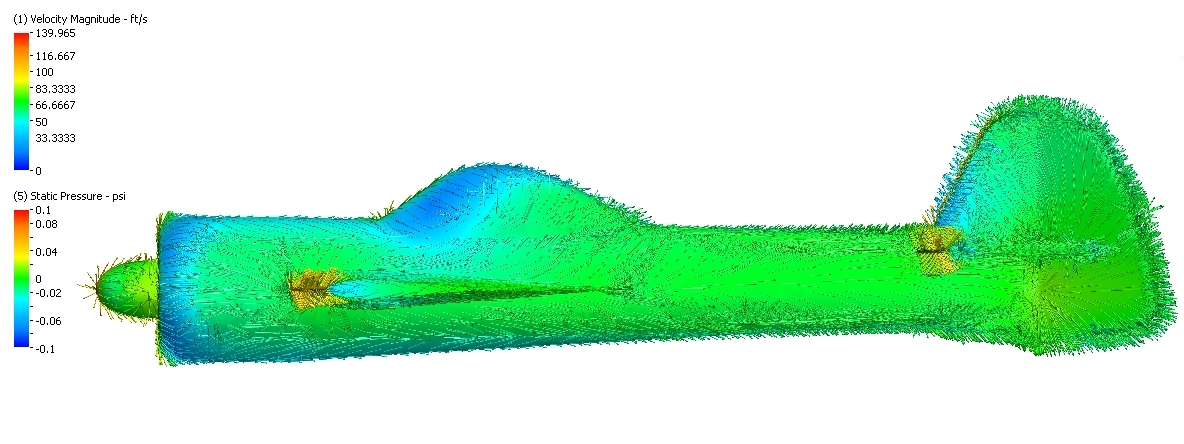
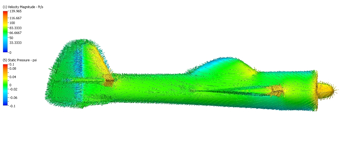
at the risk of bogarting this thread, I am going to post the results of a little CFD study I am doing in my spare time.....
I will first run the same model at 30 degrees beta with the horiz-stab in 3 positions.... "Low", "High" and "Centered"
Hope to discover any stab position impacts on yaw-pitch coupling....
Initially.. there are no thrust forces. For simplicity and to isolate the stab location effects, I have decided to not include
the thrust nor the spiral slipstream from the prop. Perhaps later I will add this boudary condition....
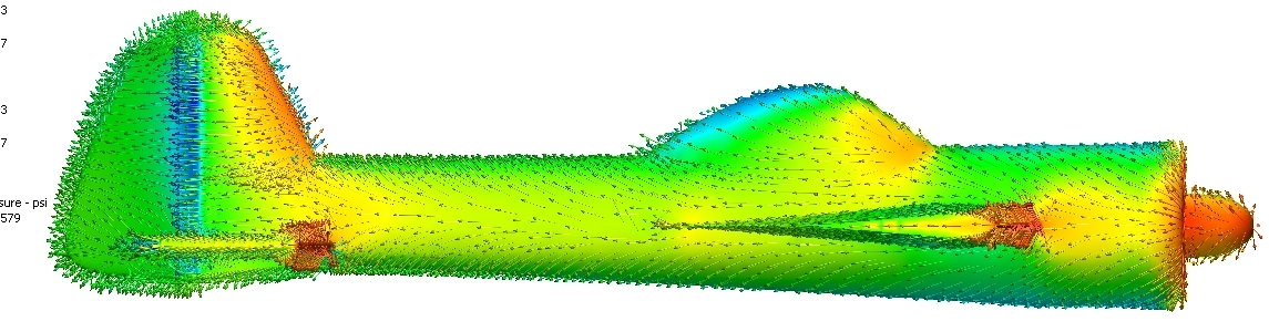
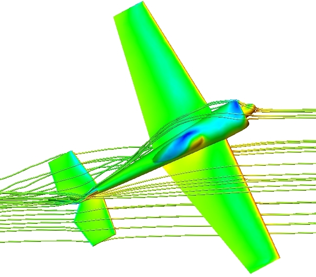
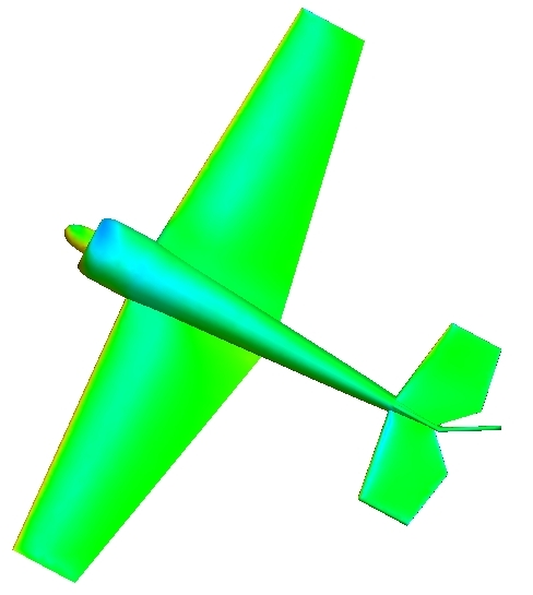
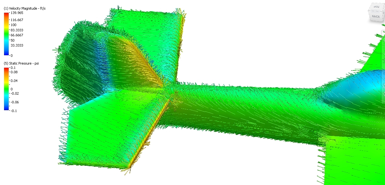
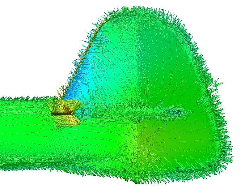
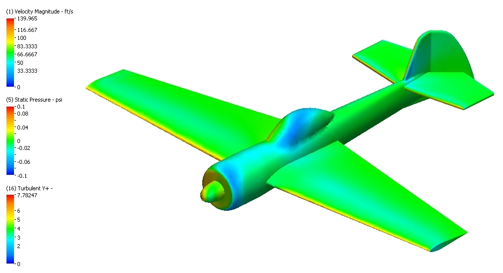
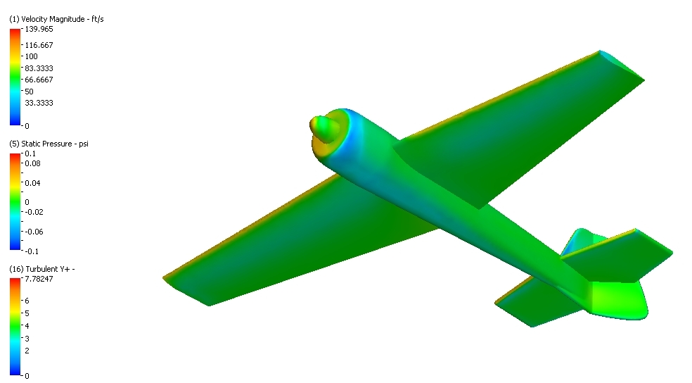
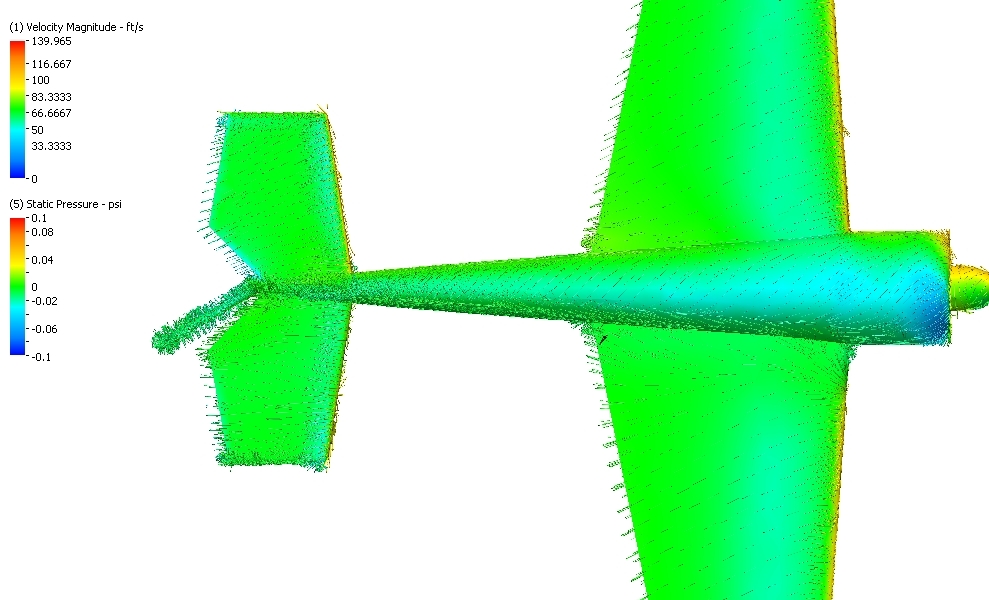
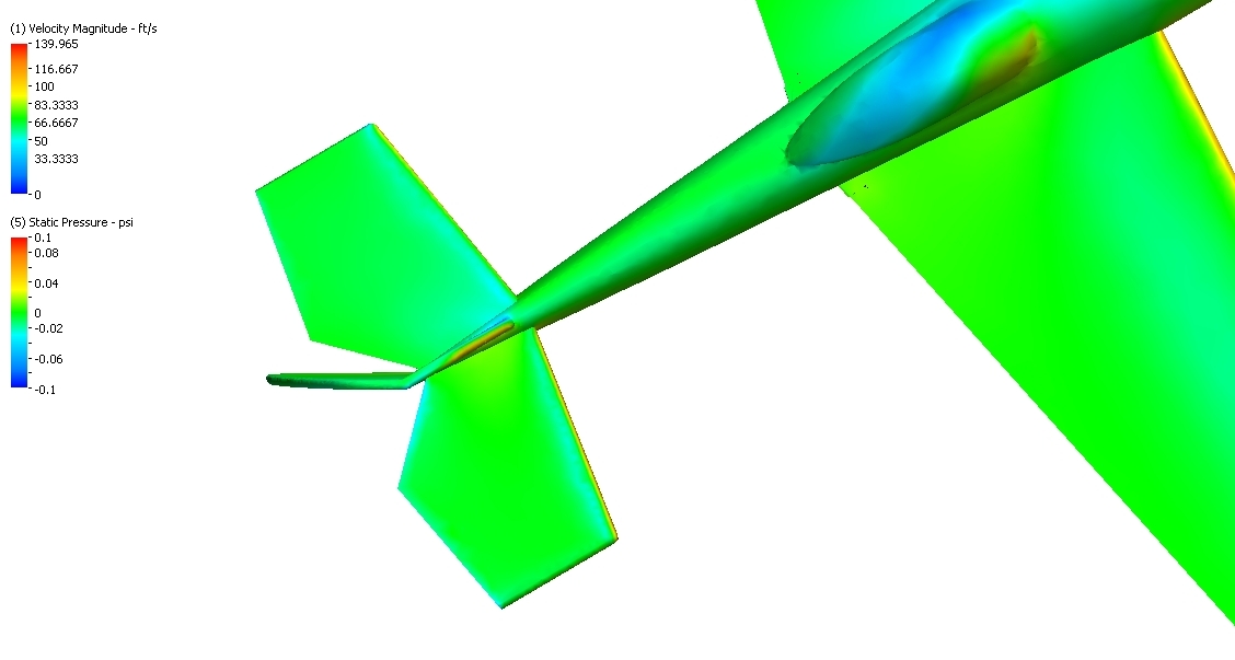
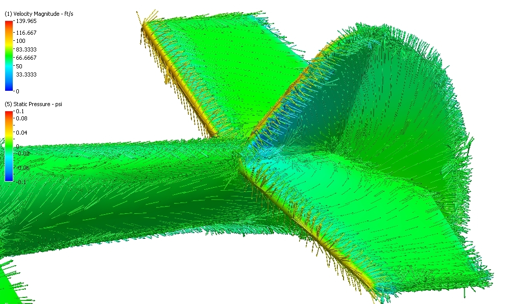
So the first set of images is of a popular scale aerobatic plane called a Yak 55. This virtual "Model" has a 78" wing
so similar in size to our pattern planes. I have located the stab in the low position
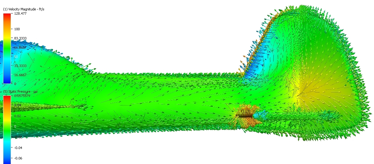
for this first run. Included are several images showing the pressure distribution and the surface vectors on the plane.
Though the vectors (Tufts) are interesting to look at, nothing is immediately revealed by these vectors.
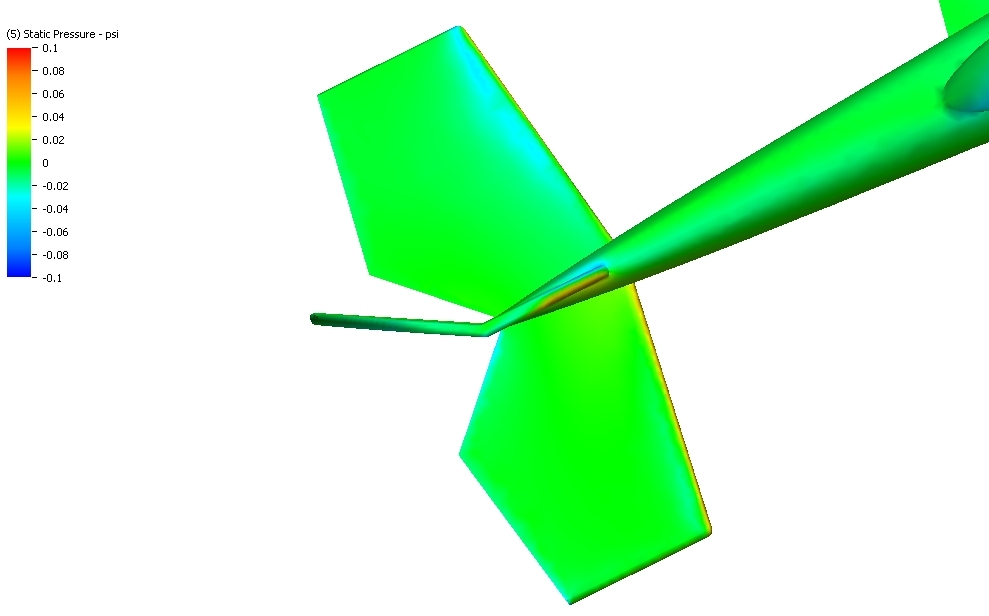
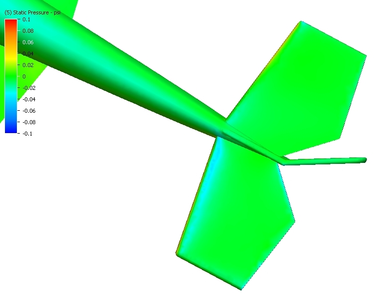
The resulting Nose-Up-Pitch is revealed by interrogating the pressures on the horizontal tail... and it is here that
a small net force is measured pulling or pitching the plane towards the canopy.
Incidentally... there is also a Adverse Roll induced by this yaw as well...(Rolling moment opposite the rudder direction)
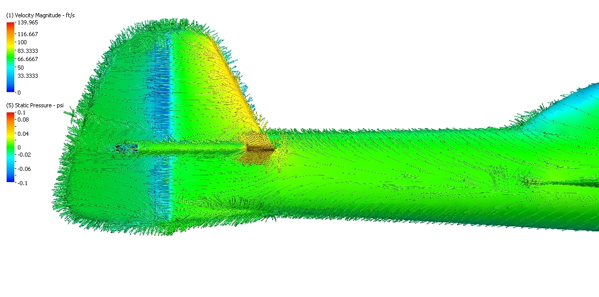
the last two images show the pressures on the top and bottom of the hz tail.... one can just barely see that the lower
side is slightly less pressure than the top side.... the actual measures force is about 5 ounces....
(Blue = low pressure, Red = high pressure)

I will first run the same model at 30 degrees beta with the horiz-stab in 3 positions.... "Low", "High" and "Centered"
Hope to discover any stab position impacts on yaw-pitch coupling....
Initially.. there are no thrust forces. For simplicity and to isolate the stab location effects, I have decided to not include
the thrust nor the spiral slipstream from the prop. Perhaps later I will add this boudary condition....
So the first set of images is of a popular scale aerobatic plane called a Yak 55. This virtual "Model" has a 78" wing
so similar in size to our pattern planes. I have located the stab in the low position
for this first run. Included are several images showing the pressure distribution and the surface vectors on the plane.
Though the vectors (Tufts) are interesting to look at, nothing is immediately revealed by these vectors.
The resulting Nose-Up-Pitch is revealed by interrogating the pressures on the horizontal tail... and it is here that
a small net force is measured pulling or pitching the plane towards the canopy.
Incidentally... there is also a Adverse Roll induced by this yaw as well...(Rolling moment opposite the rudder direction)
the last two images show the pressures on the top and bottom of the hz tail.... one can just barely see that the lower
side is slightly less pressure than the top side.... the actual measures force is about 5 ounces....
(Blue = low pressure, Red = high pressure)
Last edited by mithrandir; 10-31-2013 at 08:41 AM.
10-31-2013, 11:17 PM
#115
Thread Starter
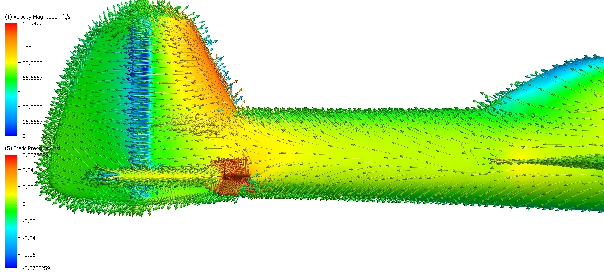
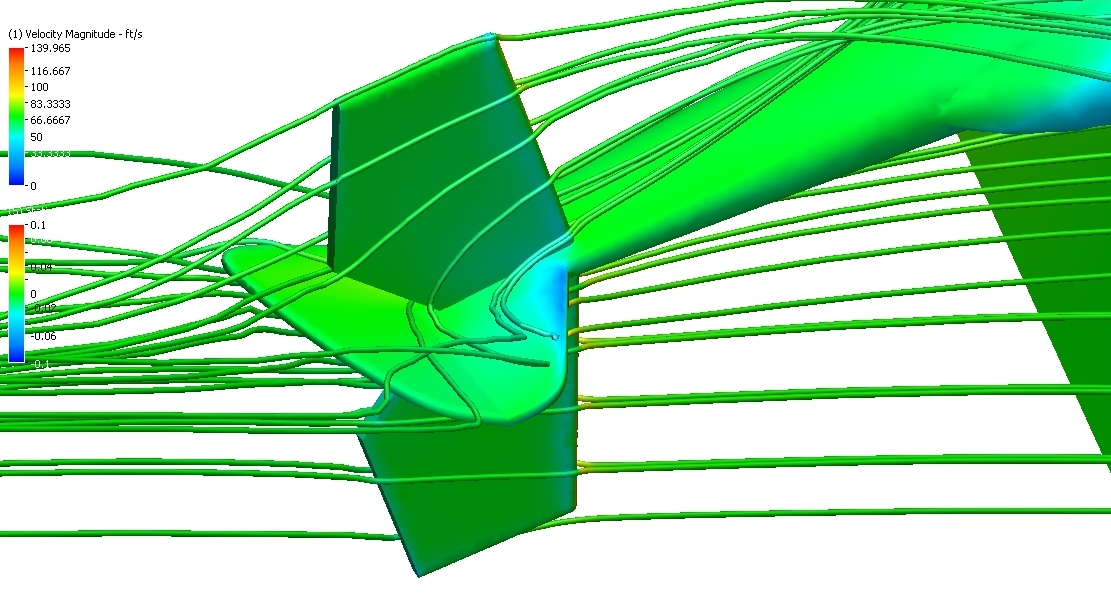
VERY nice work. It's very interesting that your simulation is confirmed by my experiments: on the low pressure side of the fuselage there's a strong spanwise flow on the vertical tail and on the high pressure side the air is moving around the top and bottom of the fuselage to the low pressure side. Thanks for sharing your results.
Which CFD software did you use? I would be very interested in running such simulations for different configurations (with and without canalizer, fin fences, fuselage strakes) and measure the actual forces involved. I have the 3D models but i'm not a CFD specialist, is it difficult to learn?
Which CFD software did you use? I would be very interested in running such simulations for different configurations (with and without canalizer, fin fences, fuselage strakes) and measure the actual forces involved. I have the 3D models but i'm not a CFD specialist, is it difficult to learn?
11-01-2013, 08:32 AM
#116
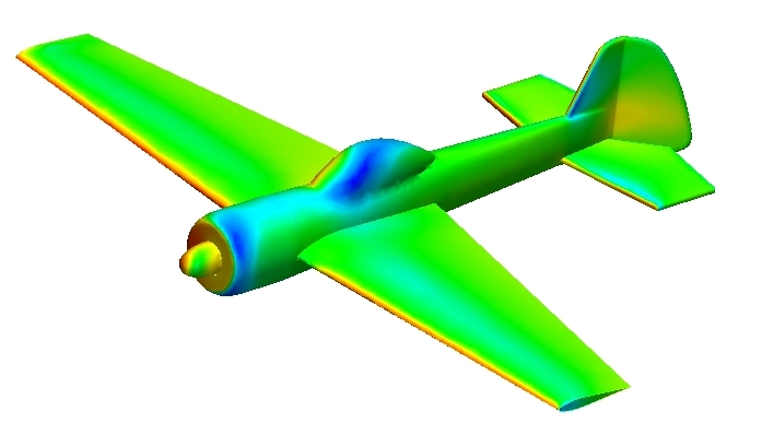
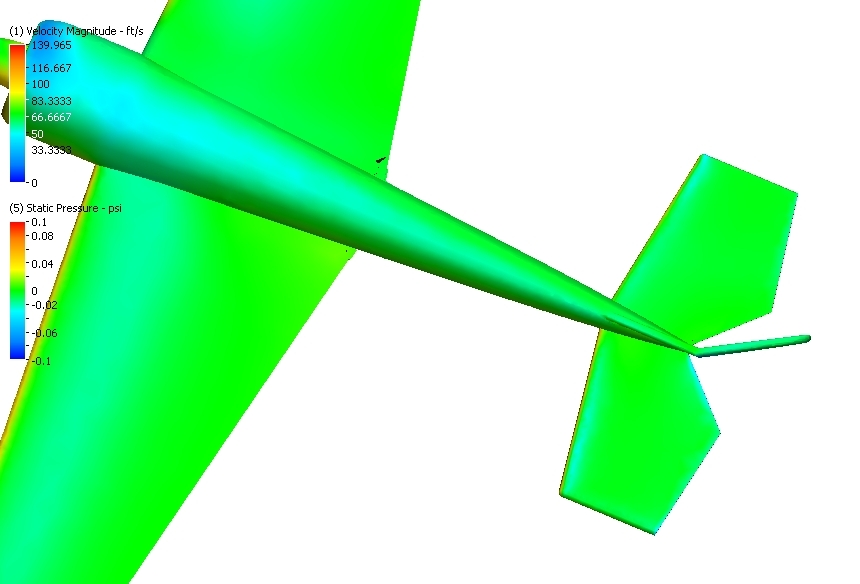
I did another run last nite... same boundary conditions... but with the horizontal stab located at the top of the fuse....
It almost looks like the low pressure on the leading edge og the vertical is superimposing on the top surface of the left stab...
perhaps this low pressure is the dominant Nose-Down pitch force???
the magnitude of the force is about 5 or 6 ounces.... and all of the force comes from the left stab... the pressures on the right
stab are a net zero...
11-01-2013, 09:31 PM
#117
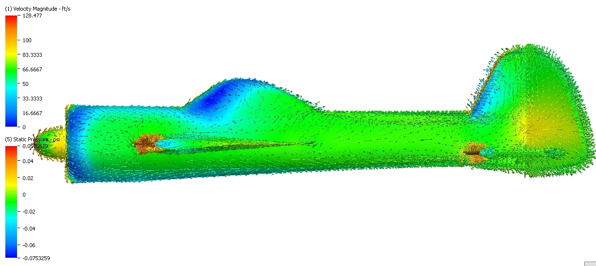
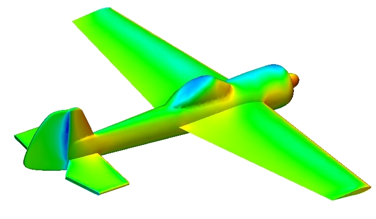
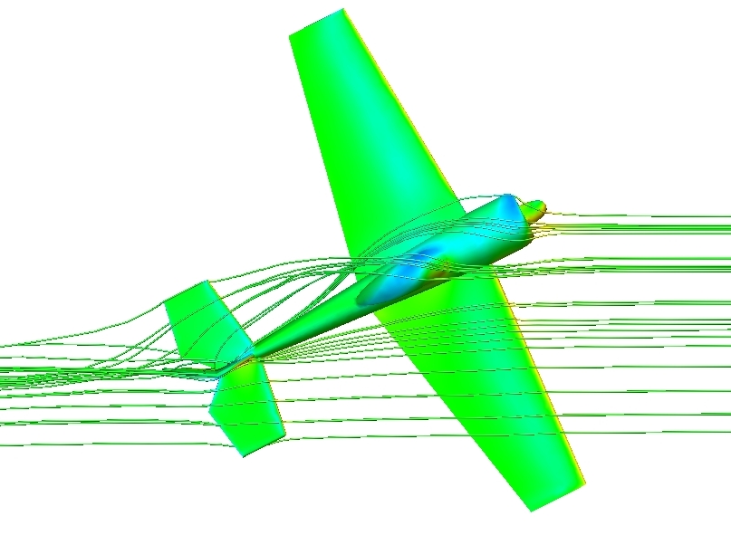
well... here is the third simulation with the stab in a central location.....
the pressure differences net out to zero... this would be where there
are no net pitch forces....
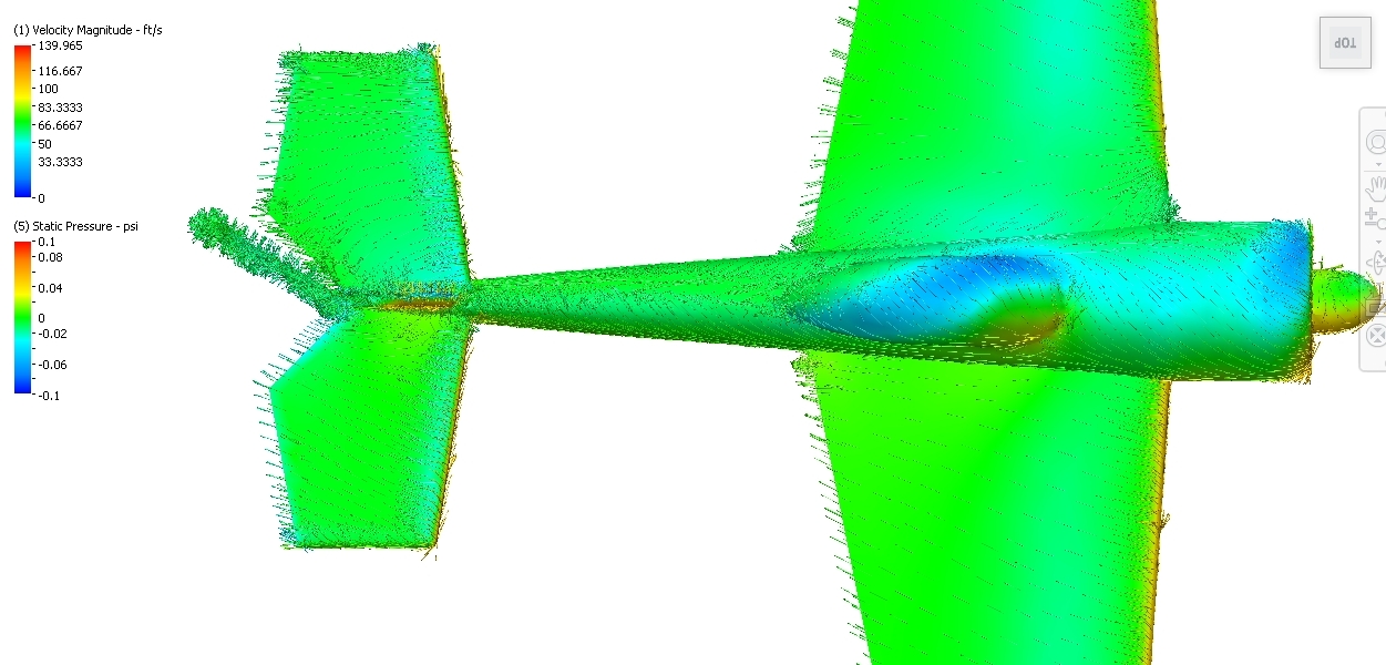
Interesting to note that in all three simulations, the flow over the right stab aligns with the freestreem...
the flow over the left stab has a lot of spanwise flow... towards the root of the stab...
additionally... there is a large spanwise flow on the side of the fin/rudder on the "Suction" side of the fuselage...
In the high stab case, there appears to be some interaction with the low pressure generated at the leading
edge of the fin on the left side.... looks like a small high pressure on the left side of the rudder in the low stab case...
I will need to more closely interrogate these results....
though I can measure pressures on the tail that indicate forces consistant with what I have experienced,
I still can't explain the mechanisms that cause the Yaw-Pitch coupling....
Last edited by mithrandir; 11-01-2013 at 09:34 PM.
05-02-2017, 10:52 PM
#119
Join Date: Jan 2009
Location: NEWCASTLE, AUSTRALIA
Posts: 342
Likes: 0
Received 0 Likes
on
0 Posts
SORRY to Hijack your thread but I have a question for our learned friends.
My OXAI GALACTIK appears to have a small twist build into the stab i.e. right stab has less incidence than the left.
Is this a design feature by CPLR or a manufacturing defect.........just curious .
Many Thanks in advance.
MAVROS
AUSTRALIA
My OXAI GALACTIK appears to have a small twist build into the stab i.e. right stab has less incidence than the left.
Is this a design feature by CPLR or a manufacturing defect.........just curious .
Many Thanks in advance.
MAVROS
AUSTRALIA
05-05-2017, 01:33 PM
#120
My Feedback: (121)
Hi Mavros,
I don't have a specific answer, but logic would suggest a manufacturing defect. I can see no aerodynamic benefit to asymmetrical stab incidence. How does it fly? Have you trimmed out the airplane satisfactorily? I would predict some pitch trim anomalies especially as speed varies and possibly some roll issues. That airplane has plug-in stabs, I believe, is the stab twisted (actually built crooked) or is there a problem with the stab tube holes?
Regards,
Will
05-07-2017, 05:31 PM
#121
Join Date: Jan 2009
Location: NEWCASTLE, AUSTRALIA
Posts: 342
Likes: 0
Received 0 Likes
on
0 Posts
Well curiosity took the best of me today Will and I measured the incidence on the stabs.
With both elevators flush with the stabs there appears to be .1 degree more incidence on the right ....no big deal really......
This is consistent with elevator levelling i.e. right elevator slightly up in order to be level with left elevator.
Initially when I was trimming there was a very slight corkscrew effect during looping with the elevators flush with the stabs ....this was fixed by levelling the elevators using the Carbon rod method and the corkscrew went away.
Important to note here is that levelling the elevators with the long carbon rods the stabs are not flush with elevators.
The model flies very nicely however with tremendous amount of authority on the rudder but needs to be flown a little faster to maintain longitudinal stability.
Maybe if I didn't have the Carbon rods I would have been none the wiser...
kind regrds
Mavros
kind regards
Mavros
