


Plane Measurements (neg Gs / down elevator loop part trois)
 09-06-2014, 01:45 PM
#1
Senior Member
Thread Starter
Join Date: Jun 2010
Location: Medfield, MA
Posts: 172
Likes: 0
Received 0 Likes
on
0 Posts
One of the suggestions in the other threads is to check set up. Did some measurements on my plane. This was simply with a metric ruler and a CG stand as I don't have an incidence meter (but I can do trigonometry.)
Span: 1470mm
Wing Area; 0.35535m
Weight: 2.934Kg (6 lbs 7 1/2 oz)
I don't know if that's heavy for a plane that size or not. It does feel heavy at times even though I have enough power for unlimited vertical.
CG: near as I can tell, I've been flying it at about 29% of MAC. If I move the lipo pack back 1cm, I should be able to get it to 30% and if I move it 2cm, it should be about 31%. More than that and I'd have to reroute some stuff. I may try those settings next time I fly and see if it feels different. (It took me a huge amount of measuring what I hope is close to an accurate measurement. I thought I had all the calculations done on a wing panel and started using that but then realized that the taper in the fuse increased the sweep and I had to take that into account and redo all the calculations.)
Wing Incidence: +1.85degrees. I calculated that by taking the inverse sign of an 11mm height difference over a 341mmm chord. The plane does not have adjusters so changing that would involve surgery to the alignment tab slots.
The motor box I did not measure but I know it came stock with 2-3degrees of right and maybe 1 degree of down. I'd have to look it up.
If any one cares to comment on how that setup would affect flight characteristics, have it at, I'm all ears.
-l2t aka Ken
 09-06-2014, 04:21 PM
#3

I'm not a pattern guy. Hopefully that changes over the winter. So... I've been reading quite a bit. One of the trimming guides talks about 1/2 degree positive wing incidence, 1/2 degree down on the motor and then adjust the stab to remove any trim when you get close. I think he also talked about having the balance point at around the 25% mark. It's a long read and may be an even longer time to get the trim right it appears to be the right way to do it. Here is the link... http://images.rcuniverse.com/forum/u...18/Om32351.pdf
Ken
Ken
09-06-2014, 04:52 PM
#4
Senior Member
Thread Starter
Join Date: Jun 2010
Location: Medfield, MA
Posts: 172
Likes: 0
Received 0 Likes
on
0 Posts
I didn't measure the stab as I didn't have time. Also, the fuse as a flat bottom, make it easy to stabilize for measurement. But I assumed that the bottom of the fuse is parallel with the zero line. Maybe it is not. If the flat bottom is slightly tilted up toward the tail, then the wing incidence would read a false high. If I get a chance in the next few days I'll take some more measurements. But I also wonder if picking the center line is somewhat arbitrary.
09-06-2014, 06:38 PM
#5
Yes the Datum or center line as you call it can be an arbitrary thing. It can be anywhere on the airframe and need not follow any particular line. From what I've read many times it is the base of the canopy or the top of the fuse where the canopy sets. If push comes to shove, set the wing at "zero" and see where the engine and stab wind up. I would invest in a incidence meter. The meter will save you HOURS in setup time.
Ken
EDIT; Try the top of the fuse thing. I have a "bubble level" app on my smart phone that seems to work quite well. In addition to the bubble it gives a digital reading of the level in number format.
Ken
EDIT; Try the top of the fuse thing. I have a "bubble level" app on my smart phone that seems to work quite well. In addition to the bubble it gives a digital reading of the level in number format.
Last edited by kenh3497; 09-06-2014 at 06:40 PM.
09-06-2014, 08:08 PM
#6

Get the airplane on a flat surface and block up the tail until the firewall is 90 degrees to the surface. Then you can measure from the surface up to the LE and TE of the wings and stabs. Don't be afraid of needing to make changes. I have elongated holes for anti rotation pins many times. My favorite method for this is to file the hole slightly larger and the direction it needs to go. Then I will epoxy a fiberglass tube sleeve in place. This works out great as not only do you get the change but the anti rotation pin no longer runs on wood.
09-08-2014, 02:28 AM
#7

The datum of the plane is not arbitrary and it is set at a particular line of the fuselage. The designer of the plane would have already determined where that is.
There is no real point setting the firewall square and then measuring from that as you don't know how many degrees down thrust has been built in.
I wouldn't assume just because the bottom is flat, it is parallel with the datum. Most models tend to taper up at the back.
You need to find out from the manufacturer (if you can), where the datum is. If the plane has a flat canopy base, then set that to zero and measure everything from there. the stab should be zero. Failing this, I would do the following, but you can use it to double check as well.
Set the plane up on a balance stand and set the stab to zero degrees. It is more than likely that it has been set at zero. Move the balance stand so that the plane sits at this level with no support under the tail or nose. Mark this point on the wings and you can work out the percentage of the MAC. You can now measure the wing incidence and down thrust. Also check that both stabs and wings are set at the same incidence.
If you have a true flat surface, then measuring with a steel ruler and using trig. can be very accurate. I did it that way for years. just be sure that the ruler is exactly vertical when measuring.
Hope this helps.
09-08-2014, 04:18 AM
#8

Most likely the stab is designed to be at 0 degrees, and that will become your reference. I believe you said you're flying a BJ Craft plane - other BJ Craft owners can comment on that but I don't recall reading much on people changing their stab angles in those planes.
My suggestion then is to level the plane such that the stab is set to zero and call that the datum. If you don't have incidence gages, set the plane so the LE and TE of the stab are equidistant from a *flat building surface.
As mentioned above, +0.5 at the wing and -0.5 to -1.0 at the motor are very common setups. This is exactly how I set my plane up and it's flying beautifully - I left the stab alone and called that the datum. I added wing incidence to +0.5 and removed negative motor thrust to either -0.5 or -1.0 (can't remember right now). Then I followed the trim charts to get my CG dialed in and to verify the proper settings of the thrust line and wing incidence.
Often it is more difficult to adjust the stab than it is to adjust the wings. Your plane may be different (like if your wings are recessed into the fuse and there's no wiggle room) in which case you may want to set the wings to +0.5 degrees and adjust your stab.
Wing adjusters are easy enough to install. You can do one adjuster at the front of the wing to allow the back to move freely, then temporarily pin or clamp it in place. The typical wing adjusters make it tough to adjust both the front and the back the same amount, but there is a new set on the market which I haven't used yet. When you find the right adjustment you can then make it permanent.
Last edited by Jetdesign; 09-08-2014 at 04:24 AM.
09-08-2014, 09:02 AM
#9

The true thrust line on any model is the difference between the stab incidence and the engine thrust. The measurement standard is what you want to find.
On my designs that standard is always the canopy base , I make it so it`s easy to find the reference because I`m constantly tweaking and learning new things.
Finding That standard can be done a few ways . If you have adjustable stabs ,you can use the motor set it to no more .5 down then measure the stabs if they are not at zero, set them to zero while the engine is at the standard of .5 neg. If the stab is not adjustable you may have better luck setting the standard with the stab at Zero and adjusting the engine thrust to .5 down. Then from there start with .5 positive in the wings.
If nothing is adjustable, Learn how to use a Dremel tool
If you have .5 neg in the engine and the airplane pulls to the canopy you have one of two problems, incidence in the wings are not enough, or the stabs are not perfectly aligned with each other may be the c/g is too far forward as well! It could also be a design problem or not enough incidence in the wings.
All this is explained in my trimming guide Here http://www.ckaero.net/blog/triangulation-trimming-2/
This is the forward to my Philosophy on trimming the 4 page laminated flow chart is where the rubber meets the road
and an easy to read field reference
Bryan
Last edited by flyncajun; 09-08-2014 at 10:20 AM.
09-08-2014, 11:26 AM
#10
Senior Member
Thread Starter
Join Date: Jun 2010
Location: Medfield, MA
Posts: 172
Likes: 0
Received 0 Likes
on
0 Posts
Thanks for all the info. I noticed by canopy base is a straight line and there's a trim line parallel to that the entire length of the fuse. I also noticed that the flat surface of the bottom of the fuse is not parallel to the canopy base and tapers up a tad. That's probably why it measure too high at 1.85degrees. I'll remeasure when I get a chance.
My guess is everything as far as incidence is going to be pretty reasonable as this plane was design by BJ. At least I bet it's close enough that I'm not going to want to mess with changing alignment holes until I learn a lot more.
But measuring all this stuff and learning about it is increasing my knowledge so it's not in the least bit wasted time.
09-08-2014, 11:43 AM
#11
There is a great deal to learn and consume in this thread about the subject here in the Aerodynamics forum http://www.rcuniverse.com/forum/aero...-trimming.html
Eat the fish and throw the bones away
Eat the fish and throw the bones away
09-08-2014, 04:24 PM
#12
There is a great deal to learn and consume in this thread about the subject here in the Aerodynamics forum http://www.rcuniverse.com/forum/aero...-trimming.html
Eat the fish and throw the bones away
Eat the fish and throw the bones away
 I guess the best way to do that is to fly and trim, keep notes and find a mentor. I can do everything except the mentor thing. It's kind of a pattern wasteland here in north central Iowa
 My other problem is my OCD
") I'm still trying to figure out which branch of rc I want to specialize in.
I'm still trying to figure out which branch of rc I want to specialize in. Ken
09-08-2014, 04:51 PM
#13
VERY good advice except it's hard for new guys like me to separate the meat and the bones I guess the best way to do that is to fly and trim, keep notes and find a mentor. I can do everything except the mentor thing. It's kind of a pattern wasteland here in north central Iowa My other problem is my OCD I'm still trying to figure out which branch of rc I want to specialize in.
Ken
I guess the best way to do that is to fly and trim, keep notes and find a mentor. I can do everything except the mentor thing. It's kind of a pattern wasteland here in north central Iowa My other problem is my OCD I'm still trying to figure out which branch of rc I want to specialize in. Ken
09-08-2014, 06:06 PM
#14
Bryan's methods worked very well for me and my airplane. I took the time to read *everything and make sure I understood what I was doing before making any changes. There are other methods out there but after coming to understand the Triangulation method it really made a lot of sense to me.
I still suggest tweaking your CG in the meantime to see what happens while reading up on trimming methods. Take your time and start when you are ready and have the time to commit to trimming. It can take quite a few flights and a lot of minor adjustments. It goes A LOT faster if you know someone with the same plane who has been through this with that airplane. That was a major advantage to flying the Integral. I didn't have to spend much time at all, just enough flights to dial in the CG and verify the changes I had made on the build table.
I still suggest tweaking your CG in the meantime to see what happens while reading up on trimming methods. Take your time and start when you are ready and have the time to commit to trimming. It can take quite a few flights and a lot of minor adjustments. It goes A LOT faster if you know someone with the same plane who has been through this with that airplane. That was a major advantage to flying the Integral. I didn't have to spend much time at all, just enough flights to dial in the CG and verify the changes I had made on the build table.
09-09-2014, 01:12 AM
#15


Join Date: Aug 2010
Location: Lynn,
MA
Posts: 451
Likes: 0
Received 0 Likes
on
0 Posts
I had a Nobler Control line Carl Goldberg? I had it set up with the Flaps Integrated with the Elevator! Up elevator,Down flaps and Down Elevator Flaps went up! It helped when it came to Loops. Much Tighter! You might want to try that?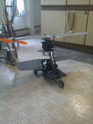

09-10-2014, 05:14 PM
#20
Senior Member
Thread Starter
Join Date: Jun 2010
Location: Medfield, MA
Posts: 172
Likes: 0
Received 0 Likes
on
0 Posts
I have no problem making a loop more than tight enough with elevator only and on low rate, maybe 50%. It's making big, round, majestic loops that I'm working on and my challenge is getting the size, trim, airspeed, power, etc. just right so that the plane doesn't waffle between positive and negative when going over the top.
Now my little combat foamie, that's another story. I have a switch that will mix full elevator up to full down ailerons; I could probably cut my own streamer if I tried hard enough.
Now my little combat foamie, that's another story. I have a switch that will mix full elevator up to full down ailerons; I could probably cut my own streamer if I tried hard enough.
09-10-2014, 05:35 PM
#21
I have no problem making a loop more than tight enough with elevator only and on low rate, maybe 50%. It's making big, round, majestic loops that I'm working on and my challenge is getting the size, trim, airspeed, power, etc. just right so that the plane doesn't waffle between positive and negative when going over the top.
Now my little combat foamie, that's another story. I have a switch that will mix full elevator up to full down ailerons; I could probably cut my own streamer if I tried hard enough.
Now my little combat foamie, that's another story. I have a switch that will mix full elevator up to full down ailerons; I could probably cut my own streamer if I tried hard enough.
09-11-2014, 01:00 AM
#22
Join Date: Aug 2010
Location: Lynn,
MA
Posts: 451
Likes: 0
Received 0 Likes
on
0 Posts
Are you using an Aerobatic wing? They have Neutral lift.Airfoil top & Bottom.Made for Reg. or Inverted Flight.You might be loosing lift with a Flat bottom wing At that point? I haven't flown a Control line Model since I was about 16. Always used Neutral wing for Aerobatics No flat bottom? Bottom same shape as Top!
09-11-2014, 01:17 AM
#23
Join Date: Dec 2006
Location: ToowoombaQLD, AUSTRALIA
Posts: 1,026
Likes: 0
Received 17 Likes
on
15 Posts
Using ailerons as flaps for looping segments means you don't have to change the attitude of the fuselage relative to the flightpath as much. Our planes are like rear wheel steering shopping carts with fixed front wheels (or like a boats if you prefer) so to change the amount of lift the wing generates we need to rotate the whole fuselage.
Changing the camber of the wing as well allows the amount of lift the wing generates to be changed with a smaller change in fuselage pitch, ie the pitch attitude of the fuselage stays more aligned with the flightpath.
I don't use it in my current ship because I can't get the ailerons to track good enough and experience annoying deviations in roll but I use them for landing with a fixed offset. I used to use it in an older ship because it had a poor wing loading and would "spring back" a bit (attitude realigning with the flightpath) when you would release the elevator especially at the bottoms of looping segment. Certainly not as noticable as the type of spring back you'd get if you quickly released the rudder at the bottom of a knife edge loop but it was noticable.
Pluses and minuses, try both and draw your own conclussions.
"Hmmm"... If it helps Scott, figure out what range of numbers you need to ADD to 9.8 to get a result between 9.8 to 0 and that might help with this whole wing generating negative lift thing at the top of a big, slow loop...
Last edited by bjr_93tz; 09-11-2014 at 01:40 AM.
09-11-2014, 01:57 AM
#24
Using ailerons as flaps for looping segments means you don't have to change the attitude of the fuselage relative to the flightpath as much. Our planes are like rear wheel steering shopping carts with fixed front wheels (or like a boats if you prefer) so to change the amount of lift the wing generates we need to rotate the whole fuselage.
Changing the camber of the wing as well allows the amount of lift the wing generates to be changed with a smaller change in fuselage pitch, ie the pitch attitude of the fuselage stays more aligned with the flightpath.
I don't use it in my current ship because I can't get the ailerons to track good enough and experience annoying deviations in roll but I use them for landing with a fixed offset. I used to use it in an older ship because it had a poor wing loading and would "spring back" a bit (attitude realigning with the flightpath) when you would release the elevator especially at the bottoms of looping segment. Certainly not as noticable as the type of spring back you'd get if you quickly released the rudder at the bottom of a knife edge loop but it was noticable.
Pluses and minuses, try both and draw your own conclussions.
"Hmmm"... If it helps Scott, figure out what range of numbers you need to ADD to 9.8 to get a result between 9.8 to 0 and that might help with this whole wing generating negative lift thing at the top of a big, slow loop...
Changing the camber of the wing as well allows the amount of lift the wing generates to be changed with a smaller change in fuselage pitch, ie the pitch attitude of the fuselage stays more aligned with the flightpath.
I don't use it in my current ship because I can't get the ailerons to track good enough and experience annoying deviations in roll but I use them for landing with a fixed offset. I used to use it in an older ship because it had a poor wing loading and would "spring back" a bit (attitude realigning with the flightpath) when you would release the elevator especially at the bottoms of looping segment. Certainly not as noticable as the type of spring back you'd get if you quickly released the rudder at the bottom of a knife edge loop but it was noticable.
Pluses and minuses, try both and draw your own conclussions.
"Hmmm"... If it helps Scott, figure out what range of numbers you need to ADD to 9.8 to get a result between 9.8 to 0 and that might help with this whole wing generating negative lift thing at the top of a big, slow loop...
At the risk of repeating myself, if the pilot gets everything right, ie; speed, size corrections and elevator, the plane will not be in negative G's. Otherwise a full size plane that is rate for positive G's only, would not be able to do an inside loop. But they can.
As they say - you can lead a horse to water.