Allure Glow Build
 10-02-2015, 01:24 PM
#1

Thread Starter
My Feedback: (19)
Join Date: Dec 2001
Location: Rayne,
LA
Posts: 371
Likes: 0
Received 0 Likes
on
0 Posts
I hope you enjoy my build thread. Please understand that we all have our own technique when it comes to building and I'm very happy when someone can teach me a better way. Please keep all comments positive and on topic or keep them to yourself.
Now let's get started
Oh the joy of building a new pattern plane! I love opening a new box like a child on Christmas morning.
At first glance the Allure is a "BIG" plane! My first thoughts were "OK, this is going to weight in at 11 pounds 64 ounces"
(6,815 grams) But let's give it a try anyway... The Allure arrived without a scratch and the packing did not allow it to shift during shipping. Once I unpacked the Allure, I placed it on my table. Wow, very impressive kit. Beautiful paint, nice lines and every thing I need to complete the kit is at hand. As you can see, I placed the entire contents of the kit on the scale and it came in at 2,600 grams. My second thoughts were, "OK, I can build this under 11 pounds" (5,000 grams).
Now let's get started
Oh the joy of building a new pattern plane! I love opening a new box like a child on Christmas morning.
At first glance the Allure is a "BIG" plane! My first thoughts were "OK, this is going to weight in at 11 pounds 64 ounces"
(6,815 grams)
But let's give it a try anyway... The Allure arrived without a scratch and the packing did not allow it to shift during shipping. Once I unpacked the Allure, I placed it on my table. Wow, very impressive kit. Beautiful paint, nice lines and every thing I need to complete the kit is at hand. As you can see, I placed the entire contents of the kit on the scale and it came in at 2,600 grams. My second thoughts were, "OK, I can build this under 11 pounds" (5,000 grams).
 10-02-2015, 01:43 PM
#3
Thread Starter
My Feedback: (19)
Join Date: Dec 2001
Location: Rayne,
LA
Posts: 371
Likes: 0
Received 0 Likes
on
0 Posts
Just use a piece of masking tape to bring the two sides together. Then use a little heat to soften the fiberglass. Let cool, and fit the cowl to see you progress. You may need to do this two or three times. As you can see, mine saw spot on.
") .
.
 10-04-2015, 07:40 AM
#7
Thread Starter
My Feedback: (19)
Join Date: Dec 2001
Location: Rayne,
LA
Posts: 371
Likes: 0
Received 0 Likes
on
0 Posts
Now for the gear. I drew a line between the two closest holes for the gear bolts. Then measured the distance inward from each hole I wanted to move the gear. I marked the location and drilled the new hole. I installed the gear using one bolt and the new hole location. This will allow you to aligned the gear and marked the location for the remaining holes. I then set the blind nuts and install the gear. It's easier than it looks
 10-04-2015, 07:46 AM
#8
Thread Starter
My Feedback: (19)
Join Date: Dec 2001
Location: Rayne,
LA
Posts: 371
Likes: 0
Received 0 Likes
on
0 Posts
Here is a picture of my tail wheel installation. The tail wheel that comes with the kit is good quality.
Last edited by Jetpilot12; 10-20-2015 at 10:59 AM.
10-04-2015, 07:53 AM
#9
Thread Starter
My Feedback: (19)
Join Date: Dec 2001
Location: Rayne,
LA
Posts: 371
Likes: 0
Received 0 Likes
on
0 Posts
Now that it's on the gear, I had to put it together to see how big it is. Damn!!! That's a big plane!!!
Once again, Bryan Hebert, set a new standard for pattern planes
 10-04-2015, 09:02 AM
#10
Thread Starter
My Feedback: (19)
Join Date: Dec 2001
Location: Rayne,
LA
Posts: 371
Likes: 0
Received 0 Likes
on
0 Posts
Now it's time for the wings. As for all import kits, there are some things that need to be updated. These kits, although very nice, are assembled by people that have no clue of how to build and fly a model airplane. What I'm trying to say is, these people are not modelers. We as modelers, need to understand that it's up to us to make improvements as needed. The updates needed for my kit, might be different on your kit. That's the price we pay to have an ARF at a reasonable price.
I hate this part! I don't know why, but I have always hated to set up the alirons

Here is how I updated my alirons. In my option, the aliron mounting blocks on my kit are too thin. As you can see in the pictures, I cut two pieces of hard wood to add behind the factory blocks. This will allow a stronger support for the servo screws.
After gluing in place with CA. I used a black marker pen to color the wood. This gives a finished look to your model when the servo is mounted.
Using the straight edge of a ruler, draw a line along the side of the servo to the aliron. This line will be your measuring reference for hole placement. Now measure from the servo case to the servo arm hole you are going to use. Now use this same measurement from the reference line on the aliron to mark the hole location. Once the you have marked the location, take a measurement from the end of the aliron to the mark. Turn the wing over and use this measurement to mark the top side of the aliron. (I'm sorry I didn't take a picture for this step). Now that the hole location is marked on the top and bottom of the aliron, use a small drill bit to drill the hole on the "bottom side" "then the top". "Do not drill through the aliron"! After you have a small hole on both sides, use a small rod to push through both holes. This will allow you to make final adjustments to your hole location if needed. Once you have determined your top and bottom holes are aligned, use the proper size drill bit to finish. Install your control horn and repeat on opposite wing.
10-04-2015, 12:16 PM
#13
Thread Starter
My Feedback: (19)
Join Date: Dec 2001
Location: Rayne,
LA
Posts: 371
Likes: 0
Received 0 Likes
on
0 Posts
To install the stabs, I used the same technique as the wings. I did give more detailed photos for you to have a better understanding of how I did it.
You will need to first place the plywood servo mounting tray in the location you want to mount your servo. Mark the inside of the tray for a cut line. Using an x-acto knife, cut out an access hole to mount the servo. Before you glue in the tray, please remember to double each side of the tray with plywood. This will give a stronger area for the servo screws to hold. Once the servo tray is mounted and the servo is in place, I used the straight edge the same way as I did with the wings. This time I used masking tap for you to have a better understanding of what I was talking about. Remember, once you have your location for your holes marked, drill one side at a time. Then insert a rod to verify the holes are in the correct location before you drill through with the final size bit .(see photo #6). Install servo and repeat on opposite side. The stab adjusters are held in place with two screws and have predrilled holes in the adjuster mount. As you can see in photo #1, I drilled an access hole for the stab adjuster.
 10-15-2015, 08:46 AM
#19
Thread Starter
My Feedback: (19)
Join Date: Dec 2001
Location: Rayne,
LA
Posts: 371
Likes: 0
Received 0 Likes
on
0 Posts
There are blocks in all of the control surfaces. Sorry for not posting lately. We are hosting the Cajun Nationals this weekend in Crowley, Louisiana. Looks like we will have fantastic weather and about 50 pilots Chip Hyde, Brett Wickizer, AC Glen and Bryan Hebert, just to name a few.
Chip Hyde, Brett Wickizer, AC Glen and Bryan Hebert, just to name a few.
Last edited by Jetpilot12; 10-20-2015 at 10:57 AM.
02-13-2017, 12:00 PM
#20

My Feedback: (1)
Join Date: May 2011
Location: Scott,
LA
Posts: 225
Likes: 0
Received 0 Likes
on
0 Posts
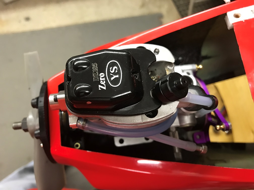
Since JetPilot didn't get around to covering the engine compartment, I figure I would post my build thread for mounting a YS 185 glo engine, in order to complete this build thread.
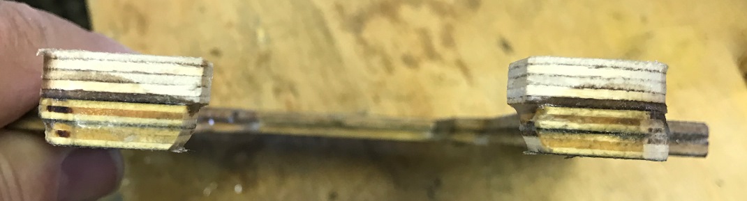
Locate the two motor mount beam plates. Place them one ontop of the other and align them, the cut out is slanted so turn one over untilthey align. Note which sides face each other and sand those two sides toprepare for gluing them together.
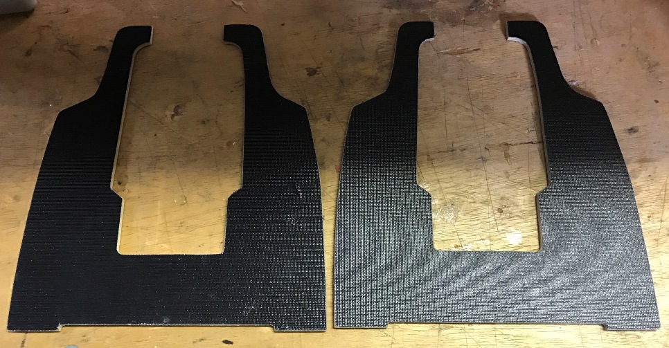

Gluethe two beam plates together using epoxy mixed with micro balloons. Clamp themtogether and allow the epoxy to set.
Locate the two motor mount beam plates. Place them one ontop of the other and align them, the cut out is slanted so turn one over untilthey align. Note which sides face each other and sand those two sides toprepare for gluing them together.
Gluethe two beam plates together using epoxy mixed with micro balloons. Clamp themtogether and allow the epoxy to set.
02-13-2017, 12:04 PM
#21
My Feedback: (1)
Join Date: May 2011
Location: Scott,
LA
Posts: 225
Likes: 0
Received 0 Likes
on
0 Posts
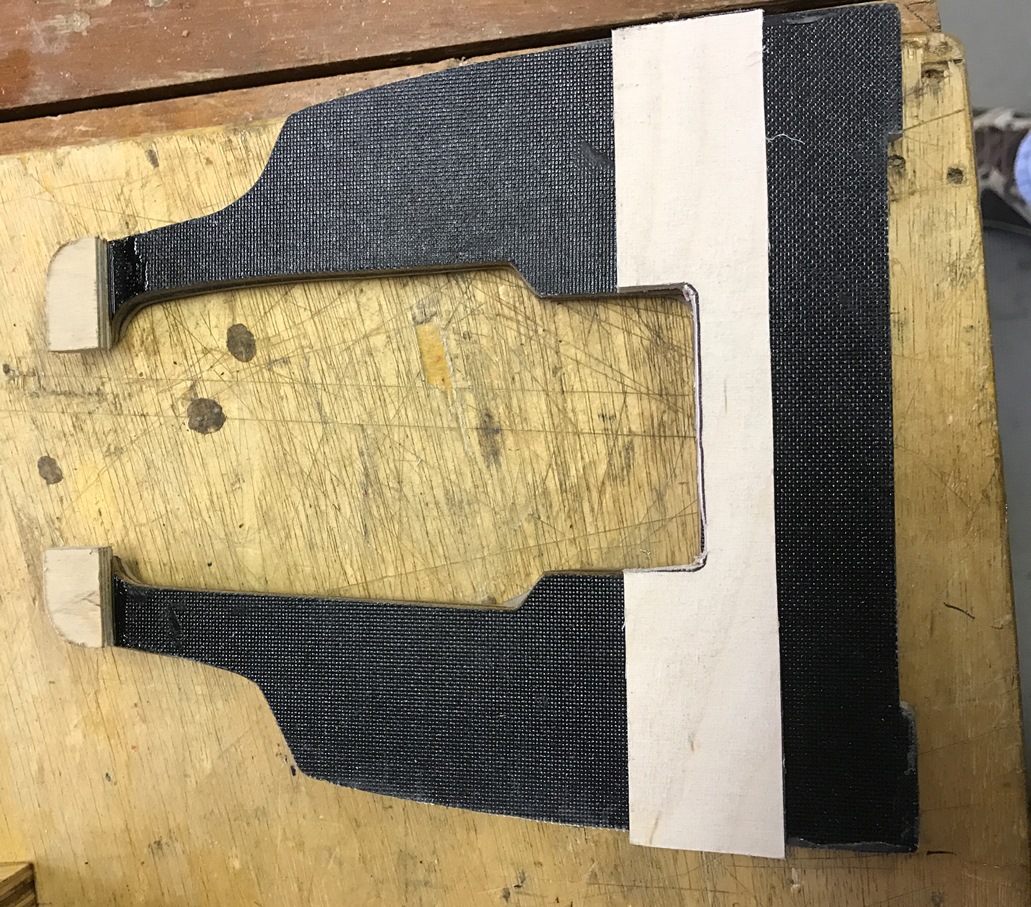
Test fit the beam plate into the nose of the Allure, andtrim it to fit snugly in it’s approximate place. Note that the engine cut outis offset to allow for side thrust. Be sure that the plate is placed in thenose with the side thrust correctly. You should install the motor mount andnose ring on the motor and set in place on the beam plate, install the spinnerback plate with a prop hub (I cut the hub from a damaged prop and use it fortesting). Hold everything in place and see if the back plate matches the nose.If the beam plate is upside down you will have too much side thrust and theback plate will not match the nose when the engine is aligned in the beam platenotch. Flip the plate over and check until you find the correct alignment. Markthe top of the plate to keep track during the rest of this process.
.
.
02-13-2017, 12:15 PM
#22
My Feedback: (1)
Join Date: May 2011
Location: Scott,
LA
Posts: 225
Likes: 0
Received 0 Likes
on
0 Posts
Cuttwo pieces of 3/16” aircraft ply to glue to the beam plate as doublers wherethe nose ring bolts will be to give some meat for the blind nuts to set into.Using epoxy and micro balloons glue the doublers in place on the side oppositefrom the side that the nose ring will sit on.
02-13-2017, 12:18 PM
#23
My Feedback: (1)
Join Date: May 2011
Location: Scott,
LA
Posts: 225
Likes: 0
Received 0 Likes
on
0 Posts
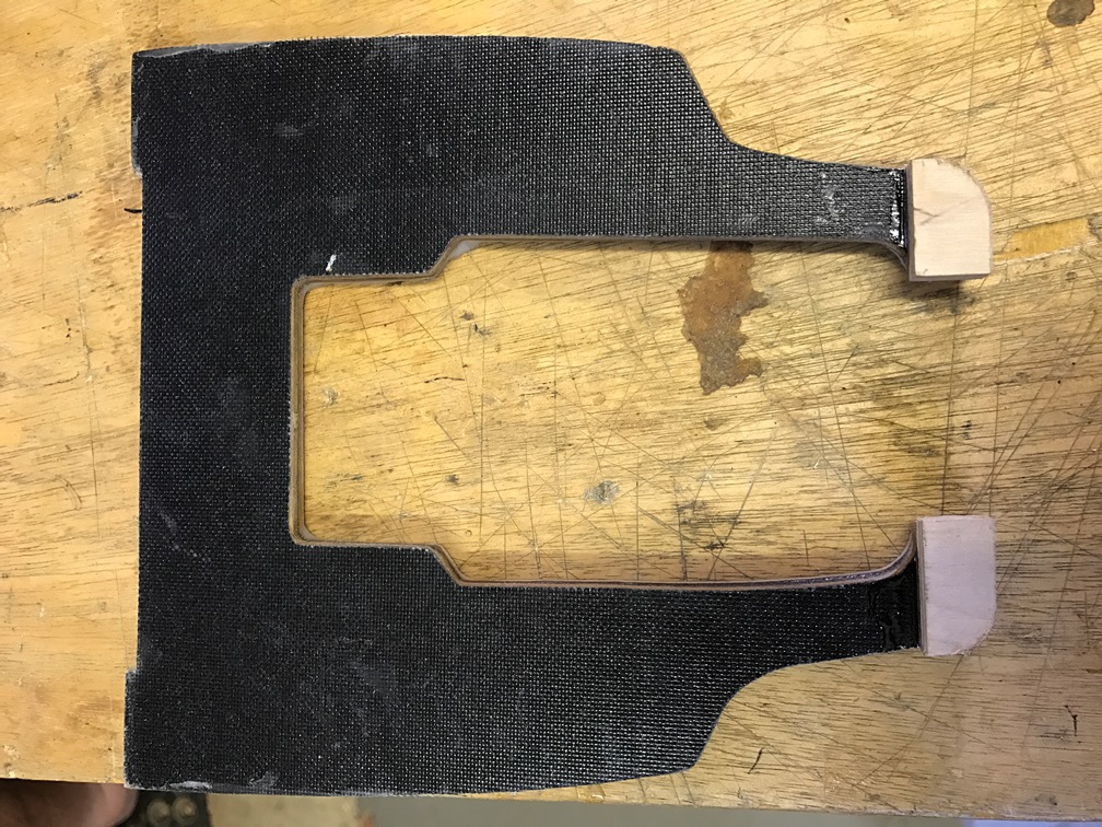
Cuta strong back from 3/16” aircraft ply to add support to the motor mount andallow for the blind nuts to have meat to set in. This should be about 1 �”wide.
Glue this strong back to the beam plate with epoxy and microballoons, on the same side as the nose ring doubler plates. Clamp and let set.Then trim to fit into the nose of the plane and test fit the engine with enginemount and nose ring to be sure the mount and nose ring do not hit any of thebeam plate or doublers.
Glue this strong back to the beam plate with epoxy and microballoons, on the same side as the nose ring doubler plates. Clamp and let set.Then trim to fit into the nose of the plane and test fit the engine with enginemount and nose ring to be sure the mount and nose ring do not hit any of thebeam plate or doublers.
02-13-2017, 12:23 PM
#24
My Feedback: (1)
Join Date: May 2011
Location: Scott,
LA
Posts: 225
Likes: 0
Received 0 Likes
on
0 Posts
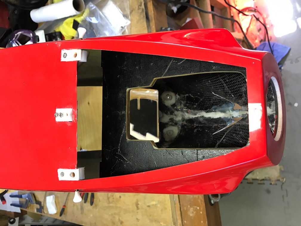
I made a nose plate jig to help hold my motor in place withthe proper alignment when fitting the beam plate into the nose.
It is the same OD as my spinner back plate, has a recess forthe motor’s thrust washer to give me the nose to spinner back plate gap Iwanted, and bolts to the motor like a spinner back plate. I aligned it to thenose of the Allure and drilled 4 small holes to use servo screws to attach itto the nose of the Allure.
02-13-2017, 12:30 PM
#25
My Feedback: (1)
Join Date: May 2011
Location: Scott,
LA
Posts: 225
Likes: 0
Received 0 Likes
on
0 Posts
Then slid my motor assembly with nose ring and motor mountinto the plane with the prop shaft thru the jig plate and using a prop hub,washer and prop nut, secured it to the motor. This held the motor in place withproper alignment to allow the fitting and positioning of the beam plate.