


29 MHz transmitter not on frequency
 04-26-2018, 08:27 PM
#1
Junior Member
Thread Starter
Join Date: Apr 2018
Posts: 15
Likes: 0
Received 0 Likes
on
0 Posts
I have an old Futaba bionic gold 29MHz transmitter that I got with the 2ndhand sailboat I bought. Now the problem is is the crystal is for 29.905 MHz channel 28 but when I test it out using my software defined radio where I can see the signal on my computer screen the transmitter is actually operating on 30.3582 Mhz. My software defined radio has been calibrated and verified to be accurate by checking the frequency of cb transmitter. To confuse things further the channel 28 receiver does respond to the transmitter with a range of about 120 meters. So what is happening here and can I tune my transmitter, I have opened it up but there is no variable capacitor that I can see to fine tune the frequency.
 04-26-2018, 10:10 PM
#2

My Feedback: (2)

Join Date: Feb 2003
Location: Palm Bay, FL
Posts: 1,046
Likes: 0
Received 0 Likes
on
0 Posts
Something's wrong with the information you're giving us. Are you in Australia?
RC channel 28 is 72.35 MHz, an airplane frequency in the USA.
The difference between 30.3582 and 29.905 is 453 kHz, an appropriate single conversion IF for a receiver. You must have been looking at the local oscillator in your receiver. I'll bet it disappears when you power down the RX. Look again-I bet you can find a 29.905 transmit signal if your SDR can tune there.
It's very possible there is no fine tuning component for the transmitter oscillator. Anyway, unless you know what you're doing you'd best not mess with it.
If the range is good enough for you, it may not be worth dinking with anyway.
04-26-2018, 10:38 PM
#3
Junior Member
Thread Starter
Join Date: Apr 2018
Posts: 15
Likes: 0
Received 0 Likes
on
0 Posts
Nothing is wrong with the information I am giving and yes that is Australian frequency allocation. No I still get 30.3582 Mhz with the receiver turned off. No the range is not good enough and I already have a antenna cut to the right length for this frequency. Anyhow I can't see why the transmitter is working on this frequency, it needs to be at the allocated frequency for obvious reasons. But thinking on your suggestion about single conversion IF of receiver I wonder if the documented frequency and channels are misleading somehow. Also I have a 27 Mhz transmitter on channel 6 27.095 Mhz that is transmitting on channel 12 27.255 MHz. Would like to understand what is going on here.
04-26-2018, 10:41 PM
#4
Junior Member
Thread Starter
Join Date: Apr 2018
Posts: 15
Likes: 0
Received 0 Likes
on
0 Posts
Just thought to check crystal for 27 MHz transmitter and it actually has 27.255 MHz printed on it so no trouble with that transmitter, just some confusion with channel number printed on the transmitter crystal holder which I will have to look into.
04-26-2018, 11:17 PM
#6
Junior Member
Thread Starter
Join Date: Apr 2018
Posts: 15
Likes: 0
Received 0 Likes
on
0 Posts
Just thought to check frequency printed on 29 MHz transmitter crystal, the sticker says 29.905 but peeling that off I see 30.360 so frequency I see on my software defined radio is correct for crystal installed so now to work out what all this means. By the way I did check the receiver in my boat and the crystal does have 29.905 MHz printed on it.
04-27-2018, 09:16 AM
#8
My Feedback: (2)
Join Date: Feb 2003
Location: Palm Bay, FL
Posts: 1,046
Likes: 0
Received 0 Likes
on
0 Posts
A single conversion receiver works like this:
There is an oscillator near the front end that mixes with the incoming signals. When that happens, sum and difference frequencies are produced. The difference frequency of the desired signal will fall on the IF frequency, usually something around 455kHz. At the back of the IF is a detector and decoder.
For your receiver, the local oscillator should be working at 30.3582. The incoming signal at 29.905 comes in and mixes producing new frequencies of (30.3582-29.905=.4532) and (30.3582+29.905=60.2632). The first frequency makes it through the IF filtering and is successfully received while the second is so far off it is effectively blocked.
The problem with single conversion receivers is something called the image. Should a transmitter of frequency around 30.8112 appear near your receiver, then it will mix with the local oscillator and give the IF frequency, (30.8112-30.3582=.453). This frequency is close enough to the desired 29 meg frequency to slip around the front end filtering of your receiver. A solution to this for the designer is to add more IF chains to knock out the images, thus dual and even triple conversion receivers.
Back to the problem at hand. If some drunk put the transmit crystal into the receiver and the receive crystal into the transmitter, the transmitter would transmit on 30.3582. Maybe not at best power, because it's 373kHz out of your assigned RC band.
The receiver, with it's local oscillator running at 29.905 would possibily receive two frequencies: (29.905-.453=29.452) and (29.905+.453=30.358). Both of these frequencies are 453kHz away from the front end tuning of 29.905, but could no doubt sneak through and be received, although poorly.
So there you have it. A weak transmiter and insensitive receiver that somewhat work.
Sorry for all the math, but hiding within the calculations is a clue that your system is obviously AM and not FM!

 04-27-2018, 11:26 PM
#10
Junior Member
Thread Starter
Join Date: Apr 2018
Posts: 15
Likes: 0
Received 0 Likes
on
0 Posts
Thanks grotto2, I appreciate and understand your explanation and indeed some drunk(hope it was not me) as you put it has put the tx and rx crystals around the wrong way although to be fair the sticker that covered the crystal was not labelled with rx but take the stickers off and the stamped print reveals which is which. I am surprised how well it worked like this which is what really confused me but the range has definitely improved with me recording 160 meters or more with the receiver inside the house, up from 120 meters with the drunk setup.
04-28-2018, 07:54 AM
#12

A single conversion receiver works like this:
There is an oscillator near the front end that mixes with the incoming signals. When that happens, sum and difference frequencies are produced. The difference frequency of the desired signal will fall on the IF frequency, usually something around 455kHz. At the back of the IF is a detector and decoder.
For your receiver, the local oscillator should be working at 30.3582. The incoming signal at 29.905 comes in and mixes producing new frequencies of (30.3582-29.905=.4532) and (30.3582+29.905=60.2632). The first frequency makes it through the IF filtering and is successfully received while the second is so far off it is effectively blocked.
The problem with single conversion receivers is something called the image. Should a transmitter of frequency around 30.8112 appear near your receiver, then it will mix with the local oscillator and give the IF frequency, (30.8112-30.3582=.453). This frequency is close enough to the desired 29 meg frequency to slip around the front end filtering of your receiver. A solution to this for the designer is to add more IF chains to knock out the images, thus dual and even triple conversion receivers.
Back to the problem at hand. If some drunk put the transmit crystal into the receiver and the receive crystal into the transmitter, the transmitter would transmit on 30.3582. Maybe not at best power, because it's 373kHz out of your assigned RC band.
The receiver, with it's local oscillator running at 29.905 would possibily receive two frequencies: (29.905-.453=29.452) and (29.905+.453=30.358). Both of these frequencies are 453kHz away from the front end tuning of 29.905, but could no doubt sneak through and be received, although poorly.
So there you have it. A weak transmiter and insensitive receiver that somewhat work.
Sorry for all the math, but hiding within the calculations is a clue that your system is obviously AM and not FM!
There is an oscillator near the front end that mixes with the incoming signals. When that happens, sum and difference frequencies are produced. The difference frequency of the desired signal will fall on the IF frequency, usually something around 455kHz. At the back of the IF is a detector and decoder.
For your receiver, the local oscillator should be working at 30.3582. The incoming signal at 29.905 comes in and mixes producing new frequencies of (30.3582-29.905=.4532) and (30.3582+29.905=60.2632). The first frequency makes it through the IF filtering and is successfully received while the second is so far off it is effectively blocked.
The problem with single conversion receivers is something called the image. Should a transmitter of frequency around 30.8112 appear near your receiver, then it will mix with the local oscillator and give the IF frequency, (30.8112-30.3582=.453). This frequency is close enough to the desired 29 meg frequency to slip around the front end filtering of your receiver. A solution to this for the designer is to add more IF chains to knock out the images, thus dual and even triple conversion receivers.
Back to the problem at hand. If some drunk put the transmit crystal into the receiver and the receive crystal into the transmitter, the transmitter would transmit on 30.3582. Maybe not at best power, because it's 373kHz out of your assigned RC band.
The receiver, with it's local oscillator running at 29.905 would possibily receive two frequencies: (29.905-.453=29.452) and (29.905+.453=30.358). Both of these frequencies are 453kHz away from the front end tuning of 29.905, but could no doubt sneak through and be received, although poorly.
So there you have it. A weak transmiter and insensitive receiver that somewhat work.
Sorry for all the math, but hiding within the calculations is a clue that your system is obviously AM and not FM!
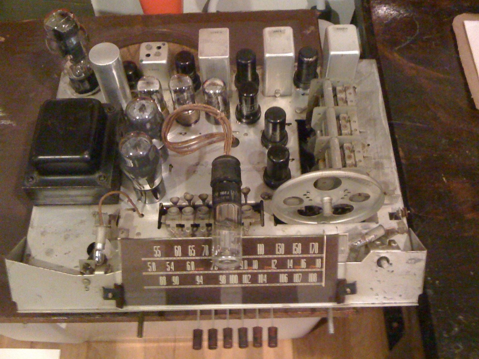
From one "radio guy" to another , Very well explained Grotto ! Figured I'd try the new image uploader here and show you the kinds of radios I collect & restore for the last 50 or so years .
 04-28-2018, 12:38 PM
#14
Junior Member
Thread Starter
Join Date: Apr 2018
Posts: 15
Likes: 0
Received 0 Likes
on
0 Posts
the other transmitter was just a simple case of differing channel designations I got from the internet, my transmitter is labelled channel 6 but many listings for this frequency call it channel 12, perhaps a historical issue where transmitters are more narrow band now so there are 12 channels instead of 6. Anyhow when I look under the stick on the crystal the frequency is what I measured and it says tx so no problem there, just my confusion.
