


Scale Modifications to the 1/3 Scale Balsa USA Sopwith Pup
 11-12-2014, 01:19 PM
#26


In these pictures you see the new smaller seat that I made from scaled down original seat template. Interestingly enough the real seat bottom was made from 16 G bulletproof steel and the seat back was 18 G. I think they must have used a different scale for metal gauge back then. I got around to painting the control column with black spray paint, it looks good but for some reason the paint doesn't want to stick to the brass. I'll have to try some other paint and see if that works better.


I wrapped the stick handle with some cotton string and rubbed it with pencil lead to give it that used look.


In this picture I've added the 2-56 hex bolts to hold the handle to the stick.

I wrapped the stick handle with some cotton string and rubbed it with pencil lead to give it that used look.
In this picture I've added the 2-56 hex bolts to hold the handle to the stick.
Last edited by AndyF; 11-12-2014 at 02:06 PM.
 11-12-2014, 01:53 PM
#28
Next I decided to scaled down the throttle quadrant from the original Pup drawings and then I printed them and cut out the aluminum.


To create the throttle lever, I spun it on my lathe.


Then I filed it and sanded it to the right thickness.


After I cut out the mixture lever, I spent a lot of time filing it to get the right shape. I spun the disk on the mixture lever on the lathe. In this last picture I temporarily assembled everything using a couple of wheel collars and a piece of music wire.


Later I assembled it using some 2-56 threaded rod pieces and a 2-56 hex bolt. You can see the ball links that will hold the linkages.


I attached the indicator scale to the main frame using some metal formula JB Weld.


Here is a comparison to the actual throttle quadrant.

To create the throttle lever, I spun it on my lathe.
Then I filed it and sanded it to the right thickness.
After I cut out the mixture lever, I spent a lot of time filing it to get the right shape. I spun the disk on the mixture lever on the lathe. In this last picture I temporarily assembled everything using a couple of wheel collars and a piece of music wire.
Later I assembled it using some 2-56 threaded rod pieces and a 2-56 hex bolt. You can see the ball links that will hold the linkages.
I attached the indicator scale to the main frame using some metal formula JB Weld.
Here is a comparison to the actual throttle quadrant.
11-12-2014, 03:28 PM
#30
I created the scale mounting bracket using some brass pieces that had in my scrap bucket. I used the full scale drawings reduced to third scale as a template and cut out the pieces and soldered them together.


Here are a couple of shots before painting. I test fit them into the cockpit to make sure everything fit.


I painted the bracket and hung it up to dry.


After painting, I mounted it in the cockpit and added the pushrods.


Here is a picture of the throttle quadrant in the scale bird.

Here are a couple of shots before painting. I test fit them into the cockpit to make sure everything fit.
I painted the bracket and hung it up to dry.
After painting, I mounted it in the cockpit and added the pushrods.
Here is a picture of the throttle quadrant in the scale bird.
 11-13-2014, 05:23 PM
#33
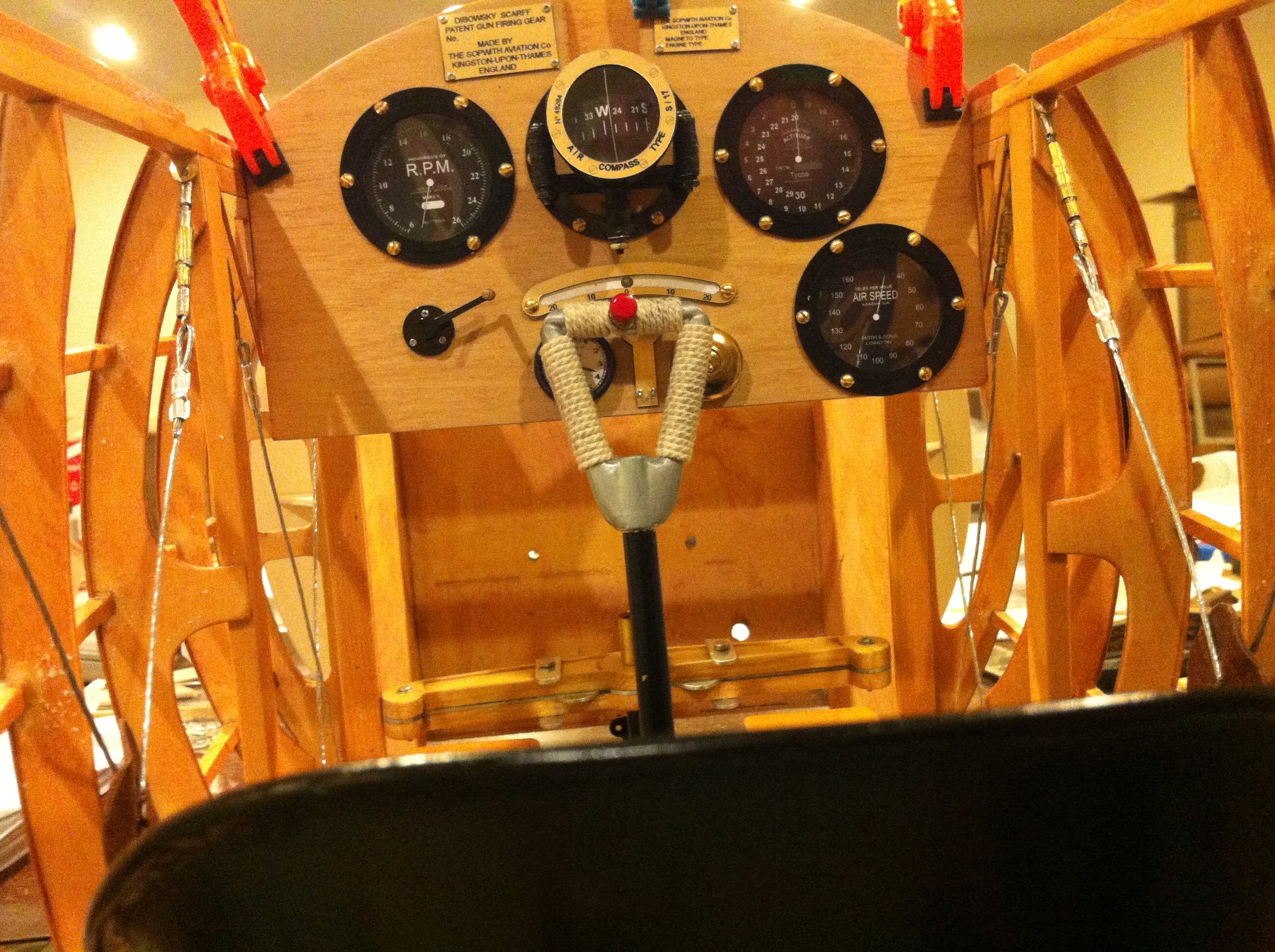
Here is a better picture of the cockpit. I used the flash and it came out pretty good (I think).
The following users liked this post:
PaulD (02-18-2024)
11-13-2014, 06:23 PM
#34

My Feedback: (2)
I created an oil sight glass for my Camel using a pill capsule. Go to the pharmacy and as for a blank one the size you need. Then fill it with clear casting resin. When the resin is hard remove the outer shell and you are all set. 
You can add dye to the resin to some oil color. Looks pretty convincing
You can add dye to the resin to some oil color. Looks pretty convincing
11-13-2014, 07:37 PM
#35
I created an oil sight glass for my Camel using a pill capsule. Go to the pharmacy and as for a blank one the size you need. Then fill it with clear casting resin. When the resin is hard remove the outer shell and you are all set.
You can add dye to the resin to some oil color. Looks pretty convincing
You can add dye to the resin to some oil color. Looks pretty convincing
Thanks,
Andy
11-13-2014, 09:14 PM
#38
My Feedback: (2)
The Bank indicator was scratch built too.. I used the same method to make the glass.. crystal clear casting resin in a proper tube. After it was extracted I bent it to the right shape before it hardened. The bracket was made with styrene plastic and the graphics were printed in cad.
11-18-2014, 10:17 PM
#42
I kept looking at my instrument panel and I finally decided that I didn't like the Mick Reeves gauges. The just didn't have the level of realism that I was looking for, so I decided to turn some bezels on my lathe. Since this is the first time I'm doing something like this it took me about 4 evenings worth of time to produce them I am also going to do the compass so that will no doubt take more time.
I started with 2" dia 6031 aluminum rod stock and put it in my 4jaw chuck. I got it trued up and then turned it down to the diameter that I needed. Next I drilled a 1/2" hole in the center and then I used my boring bit to open the hole to the right diameter for each bezel. The unchucked end is the back of the bezel. In the third picture you can see the recess that I made in the back of the bezel to accept a piece of acetate for the instrument glass.


The top two bezels are the same OD but have different IDs. In the second picture you can see the raw bezels prior to sanding and polishing. You can also see the scale instrument panel drawing that I'm working from. The center ring is the base for the compass, as such it does not have the raised ring that holds the glass in the bezels. The third picture shows the polished bezels. I was seriously considering doing some home anodizing but when I realized that I would have to spend about $200 for chemicals and supplies i've decided to paint them black instead. I took the Mick Reeves instrument faces from the light colored ones that I hadn't used and scanned them into Photoshop then I reversed the images so they had black dials. I eliminated the pointers, cleaned up the text and added a little of the green color from the light colored gauges and scaled them to fit the new bezels. I plan to make pointers out of wire and to paint them white. I'm going to hot glue them to the dials from the back to give them some three dimensional qualities. Since I printed these, I have adjusted them and changed faces slightly. The last picture just shows the polished bezels sitting over the faces.


Andy
I started with 2" dia 6031 aluminum rod stock and put it in my 4jaw chuck. I got it trued up and then turned it down to the diameter that I needed. Next I drilled a 1/2" hole in the center and then I used my boring bit to open the hole to the right diameter for each bezel. The unchucked end is the back of the bezel. In the third picture you can see the recess that I made in the back of the bezel to accept a piece of acetate for the instrument glass.
The top two bezels are the same OD but have different IDs. In the second picture you can see the raw bezels prior to sanding and polishing. You can also see the scale instrument panel drawing that I'm working from. The center ring is the base for the compass, as such it does not have the raised ring that holds the glass in the bezels. The third picture shows the polished bezels. I was seriously considering doing some home anodizing but when I realized that I would have to spend about $200 for chemicals and supplies i've decided to paint them black instead. I took the Mick Reeves instrument faces from the light colored ones that I hadn't used and scanned them into Photoshop then I reversed the images so they had black dials. I eliminated the pointers, cleaned up the text and added a little of the green color from the light colored gauges and scaled them to fit the new bezels. I plan to make pointers out of wire and to paint them white. I'm going to hot glue them to the dials from the back to give them some three dimensional qualities. Since I printed these, I have adjusted them and changed faces slightly. The last picture just shows the polished bezels sitting over the faces.
Andy
11-19-2014, 03:10 PM
#45
My Feedback: (2)
Andy,
My cowl wasn't grooved either. So I made one using a modified tool I got at harbor freight. It's a crimping/cutting tool with the cutter part cut off. The crimp part is in the aft of the tool. You crimp your wan around the cowl making the needed groove. Works decently. More work that a bead roller but you can do it yourself.
I looked at bead rollers and none of them had an end that would produce a small enough groove.
FYI You can buy cable at Lowes or Home Depot in 1/16 inch which seems about the right size.
11-19-2014, 08:51 PM
#47
I bought some 1/8" flat head rivets from MicroFasteners because their dome head rivets were too long - 1/4". The one I bought was on 1/8" long.
RVSL102FC - 1/8" long - solid - flat - Miniature Aluminum Rivets 1/16" body 1/8" head 100 pcs/pkg

Andy
RVSL102FC - 1/8" long - solid - flat - Miniature Aluminum Rivets 1/16" body 1/8" head 100 pcs/pkg
Andy
Last edited by AndyF; 11-19-2014 at 08:56 PM.
11-21-2014, 09:39 PM
#50
I finally finished designing the gauge faces for my pup. I started with the Mick Reeves gauge faces and then changed almost everything else.
This can be printed on 6 X 4 photo paper if you want to used them They are scaled for my home made aluminum bezels but they could be scaled with Photoshop. It would not allow me to upload my print file so I uploaded separate JPGs of the each gauge. I completely redrew the Altimeter using a picture of a Zenith gauge. The I redid the wording for the Tachometer and I redid the words on the Airspeed Indicator and I changed it so that it only went up to 140 MPH.


This was my template for my altimeter.

This can be printed on 6 X 4 photo paper if you want to used them They are scaled for my home made aluminum bezels but they could be scaled with Photoshop. It would not allow me to upload my print file so I uploaded separate JPGs of the each gauge. I completely redrew the Altimeter using a picture of a Zenith gauge. The I redid the wording for the Tachometer and I redid the words on the Airspeed Indicator and I changed it so that it only went up to 140 MPH.
This was my template for my altimeter.
Last edited by AndyF; 11-22-2014 at 08:45 AM.