


Scratch built german tug - Grimmersh—rn
 08-23-2013, 11:31 AM
#1
Member
Thread Starter
Join Date: Dec 2011
Location: Prague, Czech Republic
Posts: 54
Likes: 0
Received 0 Likes
on
0 Posts
Hi,
I have started to build this several years ago, because I wanted to do something while I was waiting for the airplane kit I have ordered. The blueprint was first published in 1970's and instructions are very high level and related to that time.
I knew it would be fun to build and hopefully to ride too :-)
The boat has one engine with 55mm 4 blade propeller, length is roughly 800mm. I want to detail it with some features that will add realism, like microcontroller operated lights to emulate the fluorescent tubes (blinking randomly before going on) and of course functional lightning.
I will post some pictures form the archive and describe how I have built it at that stage.
At this time, the hull is planked, glassed, final coat from the exterior and interior, lead balanced, engine and rudder are in place and now I am planking the floor. I have also cut the two sides of the upper structure and that has to come together too. Some details are already manufactured like the deck with the barrel and life saving thingy..
Hope that this will be an inspiration for someone who is starting in this kind of RC hobby like myself and I am looking forward to your comments too.
Jenda
PS. this is not exaclty the version I have plans for, but looks very similar (the upper structure has different features)
 08-24-2013, 11:12 AM
#2
Member
Thread Starter
Join Date: Dec 2011
Location: Prague, Czech Republic
Posts: 54
Likes: 0
Received 0 Likes
on
0 Posts
It all started with $5 blueprint and basic material list.
Since the plan was easy to understand, I did not have a need to do research online, yet I have bought a book about scale ship model building. The blueprint was 1:1 so transferring ribs and keel to 5mm plywood was easy. I than used dremmel tool to cut parts out and drum sander on the same tool and file to smooth the cut out.
I have glued the keel doublers and shaft to the main keel and fixed it to the plank so I can start layout the ribs into place. Now I will stop here for a minute, since I did not have any experience with ship building, I have done several things probably in different order or wrong which resulted in difficult work later on.
The hull was constructed in the normal position, not upside down with support jigs on each rib. Might be because of the interlocking design of the keel and ribs or I just thought that I can manage.
I remember using string that went from front to rear of the keel to clearly mark the centre-line so I could position the ribs as they should go.
Here are couple of pics from that stage...
J.
08-24-2013, 11:23 AM
#3
Member
Thread Starter
Join Date: Dec 2011
Location: Prague, Czech Republic
Posts: 54
Likes: 0
Received 0 Likes
on
0 Posts
When the hull structure was completed and dry (I have used 5 min epoxy) I started to plank it. The instruction talks about wooden sticks 3x8mm and I have bought those in the hoppy shop. The wood was spruce.
I thought that couple of clips would do the job and bought 10-15 of them. Soon I realised that it is too low and had bought dozens more. Ended up somewhere above 40.
I have started from the deck level down to the keel. I realised that this would get me better line at the deck level and it was easier to start with too due to bending forces.
The planking took place on both sides in parallel making sure that I don't bend the hull structure.
Again, couple of pictures form that stage. Oh, one more thing, I have used only epoxy to fix these in place, so lot of time to let it settle and harden...
Once completed I have rough sanded the hull with 80 grit paper and filled gaps with wood and smaller irregularities with putty.
J.
08-24-2013, 11:24 AM
#4
Member
Thread Starter
Join Date: Dec 2011
Location: Prague, Czech Republic
Posts: 54
Likes: 0
Received 0 Likes
on
0 Posts
At this stage it remained for couple of years until last summer/fall when I started to work on it again. The propeller shaft is from the hobby store and has motor mount on one end. Later on I have decided to use different motor, but I will get to that later on :-)
J.
J.
08-24-2013, 11:39 AM
#5
Member
Thread Starter
Join Date: Dec 2011
Location: Prague, Czech Republic
Posts: 54
Likes: 0
Received 0 Likes
on
0 Posts
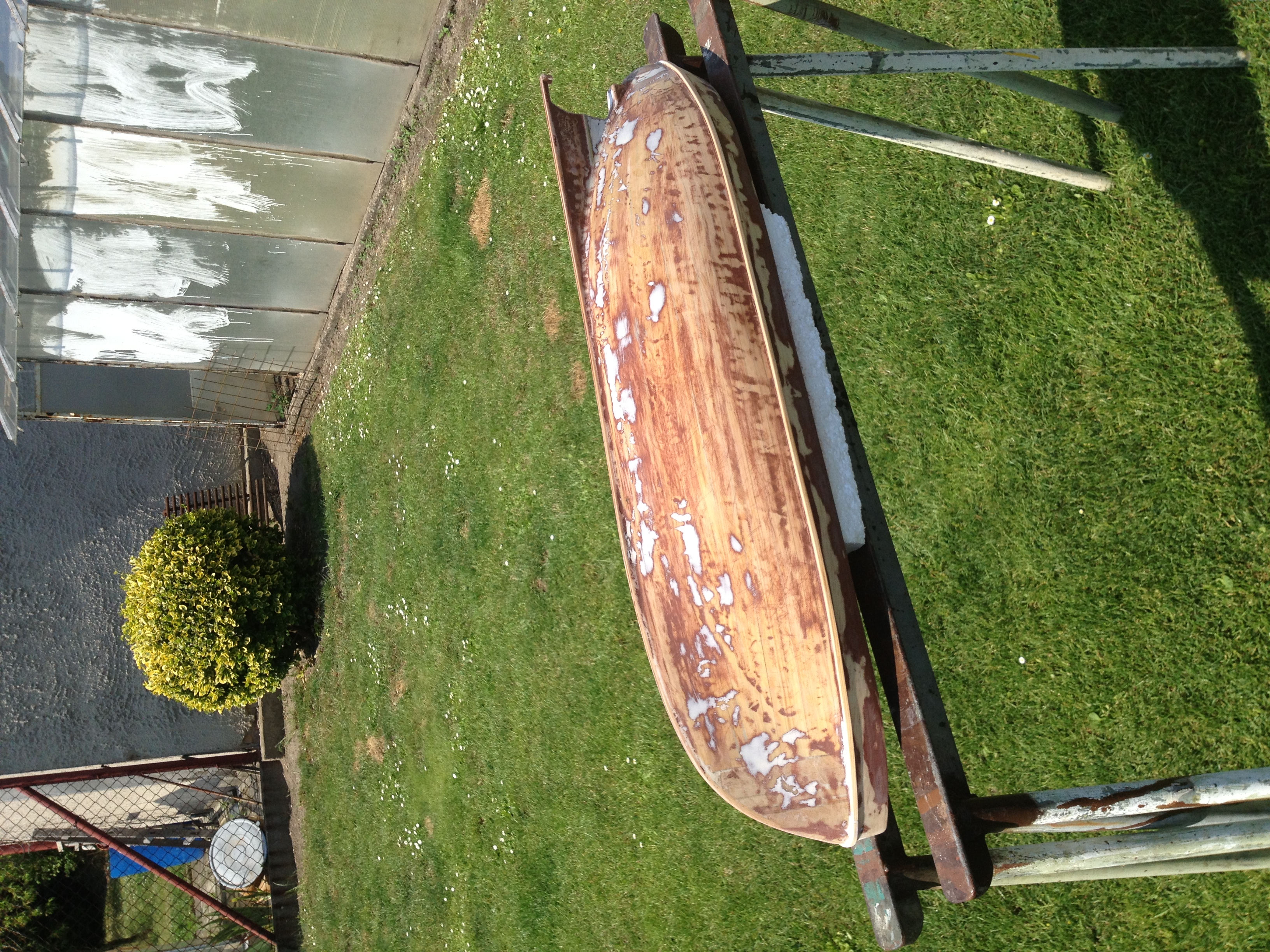
Next step in the hull build was to fill the space between front and rear and near ribs. I have used balsa wood of 10mm thickness. The procedure was simple, take the balsa wood plank, align it with the rib, draw a hull conture to it and cut it there. Since there was epoxy build from the 3x8mm planks, I needed to cut the edges of that balsa so it did have a good contact point with the keel and the rib.
Same procedure was done on other blocks of balsa, three in total for front and read and each side and next block was always made smaller to ease the shaping to match the hull curve.
From that stage I only have one picture where the balsa wood is covered with the putty.
Once cured, I have sanded it with 80 grit paper again going to finer density each time. I ended up on 320 at this stage and it was almost ready to be glassed. Notice, that the upper side of the hull, the part above deck is not finished.
Instructions say that 1mm ply should be used for that. I imagined that it will be hard to bend and went with 2mm balsa sheet instead that I had as a leftover from my plane build.
Before I glue that one in as one piece, I have decided to use 0,8mm ply sheet to cover ugly edges of the 5mm ply ribs and those sticking posts (not sure how to name it)
What I did was carefully measure each rib on one side and create that shape from the 0,8mm ply sheet. I than used woodworking glue that is waterproof to glue those in on both sides. That gave me nice and true edges and angles on each rib post (the supports for the outer skin). I have sanded bevel edge where required so I could get a nice fit of that balsa sheet. As I said before, I did not think that someone might be interested in it, so no pictures from that stage too :-(
Inside of the hull is painted with thick paint to prevent leaks (I did not know at that time that I will fiberglass it)
J.
08-24-2013, 11:53 AM
#6
Member
Thread Starter
Join Date: Dec 2011
Location: Prague, Czech Republic
Posts: 54
Likes: 0
Received 0 Likes
on
0 Posts
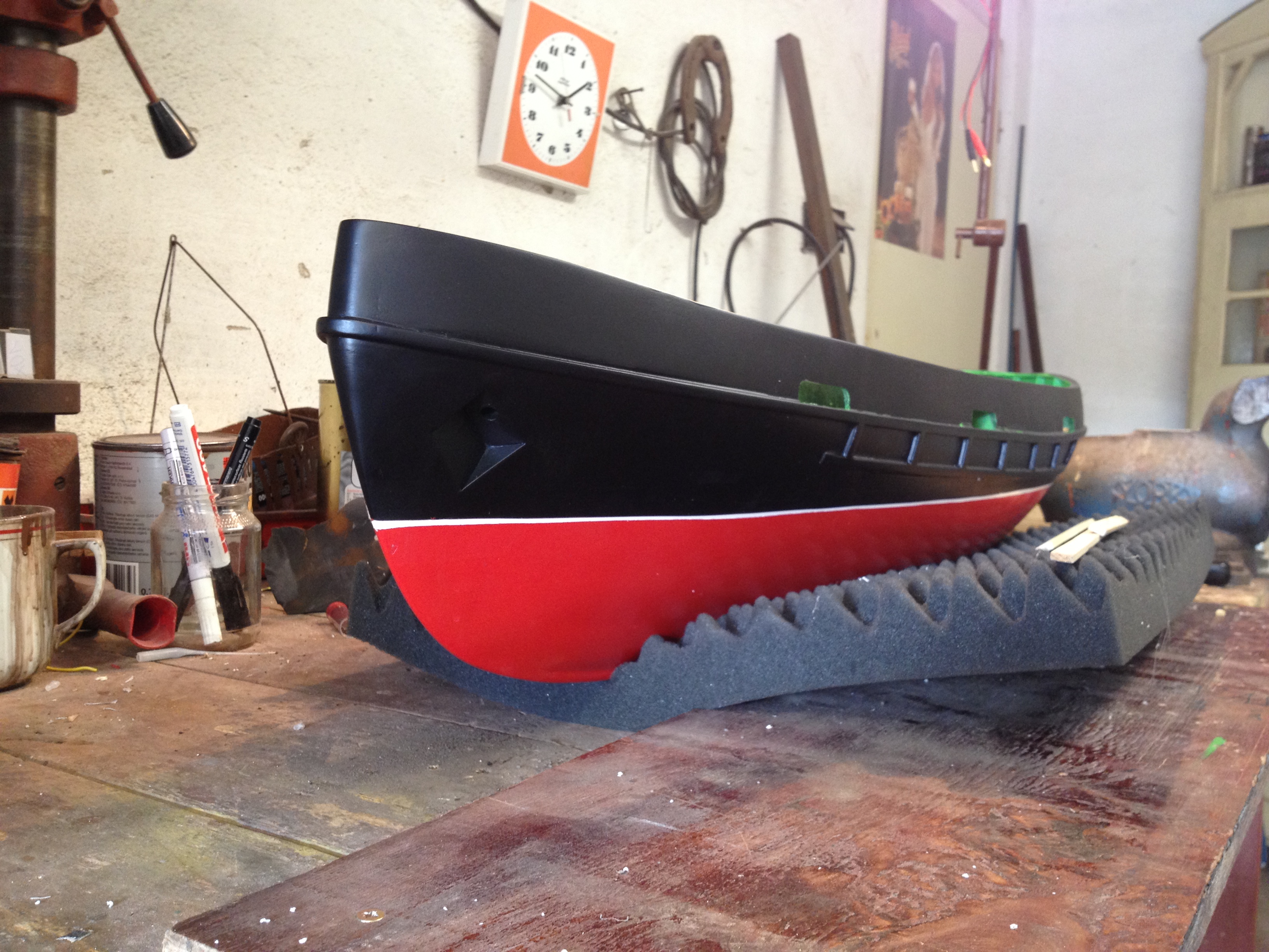
Once the empty space was filled in and nice 0,8mm ply was in place, I have glued in the 2mm balsa sheet and than on top the support rail from the same stock. It looked fabulous and started to look like a ship and I was very happy about that. I soon realised that the balsa wood is too soft and that I would damage it very quickly. This was the point when I decided to fiberglass the whole structure.
I have used glassing epoxy and 80g grade cloth for it and came to conclusion that one layer would be enough. (Hope that I did not make a mistake there, time will show)
Once the hull was glassed I have made a circle of sanding to smooth it out and than glued the weave deflector in place.
Once it was there I sprayed it with several coats of primer and several coats of putty in can (very cool thing) to make a nice and smooth shape.
At this time I have bought several parts in the hobby shop and two anchors were there too. I did not want to cut the nice hull, but I knew that I want to have those anchors there.
Again, job for the dremmel tool with cutting disc (the thicker one) and carpenters chisel to take the balsa wood out.
Once the hole was there, I have build two identical structures from 1,5mm ply that was than epoxied in place. Holes were filled with putty and everything was sanded smooth.
Than again couple of layers of primer and than couple of layers of flat black. The tube from the anchor cut-out going to the deck is left over 10mm carbon fibre tube, light, stiff and easy to sand.
J.
08-24-2013, 12:09 PM
#7
Member
Thread Starter
Join Date: Dec 2011
Location: Prague, Czech Republic
Posts: 54
Likes: 0
Received 0 Likes
on
0 Posts
I have forgotten to talk a little bit about some details that I did during the build. Here is the description...
1. The rudder shaft
rudder shaft is made from 5mm welding wire. Very tough material. I have filed a flat pad on one end, where the control horn is attached and linked by rod to rudder servo with adjustable forks (forks on thread wire on both ends)
In the hull during the construction I have drilled the 5mm hole there that is inline with pocket at the keel bottom. The pocket is made out of nylon and is simple design, cylinder with 5mm bore on one end and U groove on the other side that slides to the 5mm keel ply. In the bottom part of the hull (where it exists above the propeller) I have forced 6mm brass tube with length about 8-10mm that has 5mm inner diameter. Everything was lubed and the rudder shaft has a snug fit there, yet it is easy to turn. I doubt that water will make it thru that way.
The rudder piece itself is from one piece of 5mm ply and two pieces of 1,5mm ply covering the shaft hole. I have also thought about maintenance and when I want to take the propeller shaft out to lube the inner tubing or whatever else, the rudder must be easily removable. To be able to do that, I have filed another flat pad about in the middle of the rudder piece on the shaft and glued metal adjustable fork to the 5mm ply with the thread towards the propeller. The M2 screw would than go into that hole in the fork exiting in the inner part of the fork and resting on the flat piece of the rudder shaft. Nice and easy design.
In the rudder piece I have also used the 6mm brass tube on both ends to give support to the rudder shaft.
When testing on the hull I have noticed that I am not machine and some forces are pushing the rudder upwards towards the deck, not much, but it might be enough after some time that the bottom end would slip out of the keel pocket.
Luckily my father-in-law has a lathe in his garage and I made a small notch on the rudder shaft to approx 4mm in diameter to accommodate the C shape safety washer. Worked like a charm :-) If needed, I can take a picture of that and make annotation to it.
2. Engine
I have decided to go with brushless motor as I am flying EPP plane and have 2 li-pos at hand that I would stick to the boat once I get rid of that plane. Those batteries would serve as weight and could give some decent riding time. I have bought 45A ESC for the brushless that was designed for cars or boats, but doesn't have water-cooling like regular boat ESC's. Nice feature is the cooling fan :-)
I have used 4mm plastic sheet as a motor mount that was epoxied to two 15mm x 15mm balsa blocks. Gives stiff fixture and yet easy access to the engine. The connection to the propeller shaft is thru flexible joint (cardan shaft)
08-24-2013, 12:12 PM
#8
Member
Thread Starter
Join Date: Dec 2011
Location: Prague, Czech Republic
Posts: 54
Likes: 0
Received 0 Likes
on
0 Posts
I liked the lathe a lot so I have decided to turn functional lamps from brass rod. I did measure the 5mm LED and made a lamp around it.
Here is the result :-)
If you like them I can give you technical drawing with measurements..


Here is the result :-)
If you like them I can give you technical drawing with measurements..
Last edited by JendaDH; 08-24-2013 at 12:19 PM.
08-24-2013, 12:18 PM
#9
Member
Thread Starter
Join Date: Dec 2011
Location: Prague, Czech Republic
Posts: 54
Likes: 0
Received 0 Likes
on
0 Posts
While I was in the loop of creating details that would go on the ship later on, I have made one feature that sits on the cabin roof. It is a wooden deck with life savers and barrel of something (rum :-)) )
I have used 0,8mm ply for the planks, 3x8m as supporters that go the roof and have curve at the bottom, nylon cylinder that was covered with 0,8mm ply strips and copper wire to make a rolling ring.
The tap is made from 1,5mm hex brass rod that was cut to length and turned to 1mm diameter circle on one end that was than glued to the barrel.
Top of the tap was filed with small file.
J.
08-24-2013, 12:31 PM
#10
Member
Thread Starter
Join Date: Dec 2011
Location: Prague, Czech Republic
Posts: 54
Likes: 0
Received 0 Likes
on
0 Posts
At this stage, when the hull was painted black, rudder was working I could't resist the need to test it on water. Without the lead weight I have tested it in friend of mine's swimming pool and I must say that this is one fast tug :-)
I had to throw two larger stones in the hull to make it go down a little so the 4 blade brass propeller won't stick out of water and grab air. The power is big, when I was holding it, it was like holding 2-3 kilos of weight.
Satisfied with the power and fact that it had no leaks I was almost ready to move back to the workshop. I have noticed that the turn radius is bigger than the pool diameter which might be the problem of propeller running at almost no speed or more likely the need for bow thruster.
I have decided not to go with the bow thruster at this time because I want to ride it on water this year :-))
J
08-24-2013, 12:47 PM
#11
Member
Thread Starter
Join Date: Dec 2011
Location: Prague, Czech Republic
Posts: 54
Likes: 0
Received 0 Likes
on
0 Posts
A lof of fiddling was done on the hull. I have glued in the rub guards on sides of the hull, than again spray it with flat black thinking of how the finish is nice to realise moments later, that I need to make another cut to the hull. That is the water exit holes from the deck level. Again, job for my dremmel tool. I have used 8mm drill bit for wood (the one with the leading spike) and cut the two holes not at the very edge, but a little bit off so I won't do any wood chipping of balsa from the inside. I was not so lucky and did chip it in two places. The cutouts were enlarged with the sanding bit to correct shape.
I have spent a lot of time spraying the white waterline on the hull. Had problems with masking tape and the colour leaking under it, or not being able to pull other kind of masking tape off. Quite frustrating afternoon with a lot of #@%$#@ words :-). Finaly I have sanded what I have sprayed on at the water line level and did it one more time at once, not in sections. On the final attempt I was ready to go with red/black scheme without the white line, but I did make a nice finish after all.
Interior was sprayed with green colour and some of it leaked again under the masking tape where the cutouts are. I guess that this is another point where I should have tried different order of doing things. Result is that I will used paint brush to cover some of the green colour that ended up on the outer side of the hull.
Once the waterline was on and the hull rested in for two days to properly harden, it was ready to get some dead-weight what we call lead in the air plane hobby. It was something around 1kg of old wheel lead weights that went in and still was not enough. I ended up banging flat old lead pipe that my father-in-law had in his cellar, cutting it into stripes and than hammering it flat into square kinda shape sheets.
Those were ok and I had to put one big bolt to the rear to make it nice.
What I did not realise was that when I fix it with the hot glue gun in place I will add considerable weight to it too. The result is that the water is at the top of the waterline or slightly above it like 1mm or so.
I can always remove some lead from the hull if needed.
Also, what I thought was a good idea is to put the lead as close to the keel as possible and I have distributed it to the front and rear. Batteries are in the middle along with some more lead.
What I thought was that if the weight is in front and read and the ship goes over weave, it will be harder for the weave to lift the front and there fore make it more stable or less wiggly. Other thought I have now is that it my be negative as it would go more like straight thru the weave getting water over the fence on the main deck. I guess that the first test on the pond or river will tell.
I have than covered the lead with EPP leftovers from some electronics packaging. I actually used that to make pockets for it.
J.
08-24-2013, 12:56 PM
#12
Member
Thread Starter
Join Date: Dec 2011
Location: Prague, Czech Republic
Posts: 54
Likes: 0
Received 0 Likes
on
0 Posts
Today I have spent in the workshop only couple of hours. I have started to plank the deck with the 3x8mm sticks. Before I started to do that, I have hot glued the supporting balsa blocks for the rope attachment posts. Once the deck is in place I will drill 8m hole about 10mm deep to put the painted wooden stick in and epoxy it in place.
According to the blueprint I have started with the planing from the centre line. Even though I have tried to be precise in my measurements and alignment I have clearly made a mistake at some point during the construction as the middle plank that goes from rear to access cutout and than from there to front is in the middle by eye, yet the planking structure does not alight perfectly on each side. This means that each planks has to be done individually which is time consuming, but is is nice to do :-)
Here are couple of pictures from today's work...
J.
 08-25-2013, 10:18 AM
#14
Member
Thread Starter
Join Date: Dec 2011
Location: Prague, Czech Republic
Posts: 54
Likes: 0
Received 0 Likes
on
0 Posts
I was in the workshop during the rainy afternoon and finished planking the deck. It just needs to be sanded and protected against water.
I have realised that this should have been done before I have done finish on the ribs with 0,8mm ply and before I glued in the fence.
It would be much easier to sand along the hull curve and the whole deck. Next time I build boat with wooden deck, I need to do it this way :-)
I kind of like the bright look of that wooden floor. I knew that I don't want to end up with grey or green floor right from the start. Before working on the deck, I was sure that it will be dark brown, like the roof tray with the barrel, but I am not sure now when the deck if complete.
Here is the picture that compares the dark brown and natural wood. Let me know which you like more. The upper structure will be flat white (matt).
Also, how does one usually make a transition between the deck and the hull fence to cover imperfections? I was thinking of glueing thin stripes of 0,8mm ply along those edges, or small triangular balsa, that would be easier to flex around various curves.
Also, you may notice that the carbon tubes that go from anchor pockets to the deck do not alight, that does not matter as it will be covered with brass plate which will have holes aligned.
J.
09-01-2013, 11:46 AM
#15
Member
Thread Starter
Join Date: Dec 2011
Location: Prague, Czech Republic
Posts: 54
Likes: 0
Received 0 Likes
on
0 Posts
Got cold over the last week so nothing much has been done on the boat. I have started to sand down the deck to give it smooth finish and I was thinking how to make a transition between the main deck planks and the gunwale. Even though I tried to sand it as close as possible, there are still some imperfections. I came to conclusion that I will glue on top of the main deck planks thin plywood strips from 0,8 ply that are going to be cut to fit and will mask imperfections I made before.
Hopefully I will get better soon so I can continue on the boat.
Hopefully I will get better soon so I can continue on the boat.
09-08-2013, 11:18 PM
#16
Member
Thread Starter
Join Date: Dec 2011
Location: Prague, Czech Republic
Posts: 54
Likes: 0
Received 0 Likes
on
0 Posts
Hi again,
I finally had a chance to work on the boat again. I have sanded the deck as much as I could, but still not perfect. Well at least I know now that when doing next boat with deck from planks, they have to be glued in and sanded before the gunwale is in place. I have also cut 5mm strips from 0.8mm ply to do the transition between deck and gunwale, that came out nice, not as nice as I imagined but I am satisfied with the result.
What was little surprise is how the deck came out dark. I have tested the wood protecting paint on the 3x8 stick but I guess that sanding the wood changed the outer surface a little bit and the deck came out darker than originally anticipated. Well I am not going to sand it again and paint it with different tone. Good thing is that this colour is replenishing water so I don't have to be afraid that there is a tiny hole that will let the water in.
I have also cut another side of the upper structure from 1.5mm ply as one of the halves had wood chips around drilled holes and that was on the outside so it would be pain to fill and sand.
I have also prepared the winch mechanism that will go on the deck and played a little with the brass plate to cover the anchor chain holes. Pictures of that will be a little bit later.
J.
09-29-2013, 07:39 AM
#17
Member
Thread Starter
Join Date: Dec 2011
Location: Prague, Czech Republic
Posts: 54
Likes: 0
Received 0 Likes
on
0 Posts
Long time no work on the boat :-( I had some time this weekend to work on the upper structure a little bit. I have finally rough sanded both sides and prepared all the roofs that are there and some sides. I started to glue front and rear to the side and than glue the other side to it to make the rectangular base. WIth this frame I have positioned it on the deck and make a pencil marks where reinforced corners sit. I have than drilled small protruding hole to the deck to put 5x2 round rare earth magnet in place. That would hold the upper structure in place.
I had to do a lot of sanding to the structure but I couldn't make it sit flush with the deck. Once magnets were in place I have started to glue in roofs and front windows and other parts that reinforce the structure. To make sure that it doesn't twist, I have put some weight to the front and back.
You can check from photos how it will look once finished with more detail to it. I have also prepared the mast, various boxes, rope posts, anchor winch and some other small bits'n pieces.
Hope you enjoy it. I hope to ride it on water next week, or week after latest.
Have fun,
J.
03-03-2014, 02:59 AM
#18
Member
Thread Starter
Join Date: Dec 2011
Location: Prague, Czech Republic
Posts: 54
Likes: 0
Received 0 Likes
on
0 Posts
I have made some progress on the tug. I have completed the upper structure, worked on the mast and lightning, rails and some other minor details. Also test ride was also performed and I just need to figure out what battery shall I use. I have 12V 2,2mAh PB inside, but that gives me something around 30-40 minutes ride time. I expected quite a bit more. Here are some pics for you guys...


03-03-2014, 03:14 AM
#23
Member
Thread Starter
Join Date: Dec 2011
Location: Prague, Czech Republic
Posts: 54
Likes: 0
Received 0 Likes
on
0 Posts
Few more things to complete. Fix the paint job on some spots. Install hand made fenders to sides, front and rear, spray the tug name and install custom 4ch input electronics to control lights on the boat.

 05-05-2014, 10:53 AM
#25
Member
Thread Starter
Join Date: Dec 2011
Location: Prague, Czech Republic
Posts: 54
Likes: 0
Received 0 Likes
on
0 Posts
Few more things to share. Girlfriend did the fenders (rear bumper is done and front is almost finished). I have also sprayed the name on the hull, fixed scratched paint here and there and I am still in the design of RC light switch. Prototype is already on the board. I have designed it to take 4 channels as inputs and each channel has 3 states (3 way switch on the radio). The output is 16 individual lights (set of lights) with adjustable brightness of each output channel.

and the vid is here -> http://youtu.be/5BOOOp5bgi8
and the vid is here -> http://youtu.be/5BOOOp5bgi8

