


All metal Stug iii F: experimental build
 01-29-2011, 08:46 AM
#1

Thread Starter
THis is a thread about building an all metal Stug iii Ausf.F.
Its experimental as even though Ive always wanted an all metal 1/16 tank, Icannot justify the 2000 grand or so for the plush models and Ihave:
1. no experience with metal work
2.no access to CNC plasma cutters, water cutters etc.
3. only the most basic tools (and cheap ones at that)
4. the smallest workshop in the world.
There will be no gold leaf microscopic wing nuts on this thread. Nor am Iaiming for rivet scale historical accuracy if it impacts my chance of finishing. Im only willing to spend what Iwould on a HL+metal upgrades and paints. Im working off 1:35 scale measurements.
Istarted today by cutting out the two sides of the tank. Iused a cheap jigsaw and WD40 (because Ilike the smell) with a high TPIblade. Icut both sides at the same time trying to keep them identical (ie. two sheets on top of each other). Ithen used a steel edge, clamps and files to shape the two sides. Reasonably pleased with it how it went.
I¨will do th ebase tomorrow.
P
 01-29-2011, 01:39 PM
#2
Well good start. I hear ya on the no experience, I want to eventually build a 1/6 tank "someday". Oh and yeah that WD-40 is great smelling, they should make candles scented like that for my wife.
Wade
Wade
01-29-2011, 02:35 PM
#4
Interesting project.
I do have some questions for you. Looking at what you have cut so far- how are you going to use these plates? As the StuG III
upper hull has some angles to its sides are you planning to bend the plates you cut at an appropriate point to simulate these angles?
It appears that you are planning make the hull on one piece? no separate upper/ lower hull? That at least is how it appears to me at this point.
Jerry
01-30-2011, 12:52 AM
#5
Thread Starter
The plates you see are the height between the floor of the tank and the lowest point of the superstructure roof. These plates will form the sides. Pieces with correct angles (!) will then be mounted between these plates at right angles like rafters and the angled plates hopefully mounted on them. Bending 2 mm aluminium to exact angles is not my cup of tea so i will use 1mm sheet and fil in the joints wih epoxy if Ihave to. The rest of the tnk is 2 mm aluminium. Iam not doing a classic removable top type tank. Mosty because Idont have too, If the front glacis plates and plates forward of the gun are made removable that should allow for access to the motors. A removable back engine deck should allow for everything else. The superstructure can probably remain where it is all the time.
According to what Iunderstand from pictures and help received here, the ausf f does not have angles on its side (ie to the vertical). The hullside projects straight up to form the walls of the superstructure. There are a couple of boxes or something on the side but they are at 90 degree verticals too.
Running gear can be bought in metal and I intend to mount it using the basicHLsystem of holes nd springs. I will use 1 cm square beams to hold the running gear and square up th eboottom and sides of the tank.
MY biggest problems should be the hatches, and the swing stops for the suspension arms and the mounts for the springs pistons forward and back.
p
01-30-2011, 05:18 AM
#6
Thread Starter
Today I cut the base for the stug and the base for the rear engine decks. Im not sure if this will be the final surface for the engine decks or will just serve as a structure upon which Iwill place other plates better cut.
Bending 1 mm aluminium is reasonably easy if the sheet is clamped between steel or something. Next step will be to drillthe guideholes for the suspension arms. I wont be staggering the wheels as its a far sight easier to drill both side pltes at the same time to ensure they line up. Plus Idont want the first wheelbeing too close to the gear boxes.
P
 01-30-2011, 08:26 AM
#8
I've not researched the F version so I assume you are correct regarding the sides of the upper hull.
You are well on your way to having a unique model. 2mm aluminum sheet is substantial material for this model and scale;
it should prove very robust. 2mm sheet was used for my 1/10 Hetzer. I used angled supports riveted at the
junction between plates and I also used some of the excellent aluminum solder I have. I used JB weld as filler
between plates although this requires a substantial effort to shape with files.
The most difficult aspect I found was holding the plates together in the correct relation while actually carrying out the riveting
process. My riveted joints were quite crude as I found the process awkward ( but very effective) however given time and practice it is
a very good method providing great strength.
Jerry
01-30-2011, 09:07 AM
#9
Thread Starter
You dont happen to know the name of the solder do you? I was looking at stuff named "alutite" but Ithink I,d have to be an octopus to use it.
Is there a build thread for the Hetzer? Icould learne a lot from that
Im not too fussed if I,m a degree or two out her and there except on roof of course.... with any luck Ican hide most of my cock ups with jerry cans, buckets, spare wheels, helmets and such things.
Im still puzzled about how to cut out the hatches. Idoubt very much if Im ever going to get nice cuts and get it all matched up. Iwas thinking of cutting the hatch hole template out of thin plastic, bonding it to a sheet of aluminium then using boiling Draino (Plumbo here...) to erode out the hole. Then melt the plastic off.
Or Imay just try engraving the hatch lines out of th eplate to give the impression of a hatch or something.
Its a major hassle.
p
01-30-2011, 11:21 AM
#10
I'm not sure if the brand of aluminum solder I use is the same. I suspect there are only a few makers and it is sold under various
labels. The example I have was sold by ABR products of Yuba City California USA and was called ABR No 55 "Rubbon" aluminum solder.
I've never looked to discover if they have a website as I bought it at a local militaria
show when they use to have demonstrations of their product. I recall this smooth talking fellow who used it to beautifully and seemingly effortlessly
solder soda and beer cans together. I've never been able to do that. I've gotten mixed results. I bought 1 tube of the product which contained a dozen or so
rods ( 12" in length ?) of the material as did my late father and that combined supply has proven sufficient as I don't use it much.
There isn't much information on the product on the sheet included:
Tensile 40,000 psi
Elongation 10% in 2"
Shear 31,000 psi
Melt point 717- 728 degrees F
Electrical conductivity 26 ( % of copper standard)
My construction of the Hetzer, purchased as shaped parts from ebay.de; it was some one elses project before mine. They appear to have
originally tried to glue the upper and lower hull plates with something like Stabalit Express. It wasn't very good as parts all had come apart
by the time I received it but the parts were basically ok.
I did not chronicle ever part of what I did, honestly I'm really not proud of the riveting as while it is strong enough the underside of the upper
hull is quite quite unattractive. Even though the adhesive used had for the most part failed there was enough still tenaciously clinging
to the upper hull plates I had to use a propane torch to carefully burn it off. That coupled with the roughness due to filling excess holes
and other imperfections left the inner upper hull surface 'unseemly'. One goal I had set early on which for a large part dictated this
rough appearance was to utilize absolutely as much of the originally supplied material as possible and that at times took extraordinary
measures.
The article I have written so far is here: http://tanks.linite.com/hetzer.html
I still have much work to do but I'm taking a break from it.
Jerry
02-06-2011, 05:49 AM
#11
Thread Starter
Ithink Im nearing a close on the running gear system. its the same as a standard HL except using metal. The 1 cm square bars are essentially the support structure for everything and the 2 cm angle irons are to hold all square and releive me of trying to drill lots of straight holes through the bars to hold on the floor and walls. Its rough but the roughness is hidden behind things like the suspension arems so Im not concerned, All completed with a masonry drill and files.
I wil trim o. ff the ends off then ends of the bars and angles when Iget hold of some gear boxes so Ican figure out what Ineed to mount them.
All thats left for the mounting of the suspension arems is the small offset holes to catch the spring. I may put in one or two extra to allow clocking of the spring.
All major superstructure parts are complete and its a matter of fastening them to the side walls. This should allow me to simply place plates to form the roof.
Iordered a load of small nuts and bolts but they still havent been delivered and its a hold up. As Ireally need countersunk bolts before I want to start drilling up the side walls.
p
02-08-2011, 08:02 AM
#12
Thread Starter
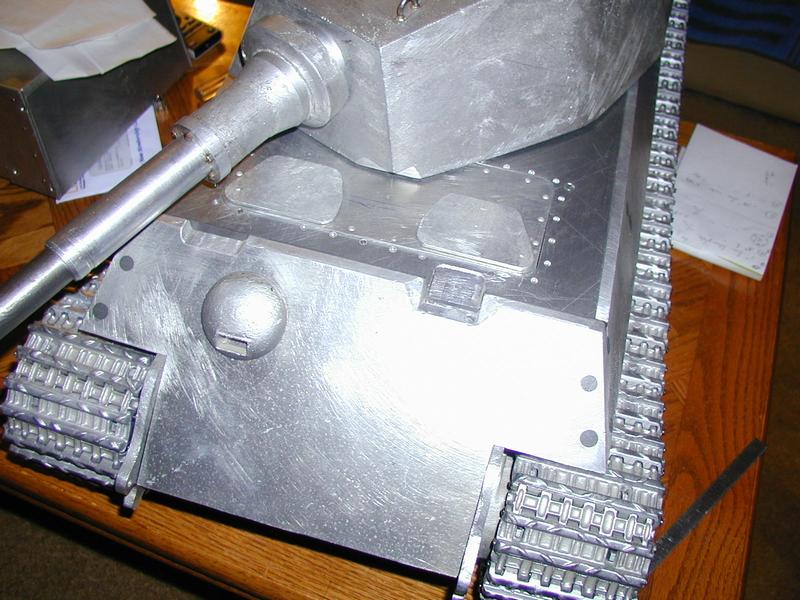
Today was the first time I got the base attached to the two sides. sorry for all the butterfly nuts but I have to take it apart and put it together 100 times. I had to remove the 1 cm bars as the weight was crazy . Replaced with angles of aluminium. Have to trim them off when I get the gearboxes. The close up is the suspension mount system - have to test it but it seems ok. The other pictures are just me holding up the other bits that have to be mounted once I know that the suspension is OK. I reckon all the bits will be held on with small brackets. The rear engine deck or else the superstructure roof should be removable. Hopefully it will proceed smoothly. I really will have to polish the metal as its getting seriously scratched up.. p
02-27-2011, 05:00 AM
#13
Thread Starter
Bit of an update.
Finally making progress on the major parts of the chassis. Next bit is to stick on the roof plates and start cutting out the missing plates.
All bits were roughed out with a hacksaw and shaped with hand files.
The running gear mounts are pretty much done... metal susupension arns have been tested and work fine. Plan is that the front armor will be held on with magnets to allow engine access. The engine deck on the back will be hinged Ihope to allow access to the interior.
The gun "box" has been roughed out and needs finishing. All fixings are temporary...Im hoping the doodahs on the sidesand such wil hide many things. Mudguards are cut out but a lot of work needed.
Ihave mato gears but donot know exactly where to cut the axxlle holes in the side walls as Ihave axle support bearings and the holes need to be exact. Any tips/help much appreciated .
P
 02-27-2011, 09:10 AM
#16
Junior Member
Join Date: Feb 2011
Location: Wayland, MI
Posts: 16
Likes: 0
Received 0 Likes
on
0 Posts
lposter, you don't really need fancy (and expensive) fabrication tools to get the results you desire.I've been a fabricator for 18 yearsbut currently do not own a welder, plasma cutter, CNC, or anything. If you take your time you can accomplish 99% of what you want with simple hand tools.I make all kinds of brackets, tabs, plates, and other items with my bench vise, an electric drill, vise grips, a hack saw, metal files, and a few lightly modified hand tools. Just throwing it out there. Good luck with your project! Looks great so far!
02-27-2011, 09:38 AM
#17
I agree with 69MarkIII regarding what you may accomplish with hand tools. Even having machine tools I still will use hand files
and other cutting tools to make some parts, especially small parts. Some of the most useful tools for me are the tiny jeweler's file
sets; they're absolutely indispensable. I get the inexpensive sets sold here in the states at Harbor Freight; they are worth their weight in
gold several times over....
lposter I hope your work inspires others to similar projects, it is good to see. Your techniques are applicable to any scale.
Jerry
02-27-2011, 10:12 AM
#18
Thread Starter
Ihave to admit I was a bit surprised myself.....although aluminium is probably as easy to work with as styrene except its a bitc? to join together.
My tolerances are fairly brutal but Ihavent encounted anything yet that cannot be covered up with welding lines or whatever. Largely gaps in joins.....
Countersinking screws in 2mm aluminium is a bit of a hassle as well. Ive been using a kind of ball shaped diamond engraving bit but its not pretty. Im also stuck for what to use as filler..... Tamiya putty doesnt stick and chemical metal of any brand is a pain in the ass.
But with the right files its a little amazing what can be done. I wish Ihad something like a very small, very powerful vice though.....holding little parts for detailing is going to be hard work.
I'll be buying all the parts Icannot make such as suspension arms and drive system.....I am well aware of my limitations and although Itoyed with the idea of making one of these "Afghan lathes" Ihave no idea whatsover about turning things.
More importantly......Ive been having a whale of a time and the sense of satisfaction when two holes line up, something doesnt look to bad or the thing holds together at all is quite remarkable indeed. The number of nights Ive been unable to sleep from trying to figure out how Im going to something are a bit worrying however.
Onwards and upwards
P
02-27-2011, 11:17 AM
#19
As filler for both seams and countersunk screw heads I have used in the past Devcon 80% steel epoxy
and more recently JB weld only because it is easier to find here. With anything you use surface
preparation is important. Both surface roughness and freedom from oil or oxidation should be assured. For some
accessory bonding I have used Stablit Express.
Here is an example of Devcon 80% steel used to hide countersunk screw heads. This hull was made
from 6,5mm ( .250") 7075 aluminium plate.
Not wanting the hull to come apart both the mating surfaces and the screws themselves were coated
with coated with the Devcon epoxy before assembly.
This hull was built 20 years ago ( a very long term off/on again project I'll finish one day!) before
I had the ability to cast parts.
Below is an example of JB Weld used for seam and screw head concealment and is also a work in progress.
I'd suggest not as liberal a application
of the material as I used here as hardened it is a test of one's patience to file or sand down appropriately.
Additionally the hatch openings in the
original parts I had received were cut square and the originals had a radius and were smaller. I did bond,
using some tiny rivets and JB Weld
an additional piece in both openings to both make them smaller and provide the appropriate radii.

Below is an example of Stabilit Express used to fix a dove tail joint I made as a repair on a damaged_in_transit
1:10 JagdPanther some years back.
The repaired section was also pinned; when the excess Stabalit was set I sanded it smooth and added a bit
of thick auto repair paint to even out the texture.
Also used the same thick paint on the Hetzer shown above. It has great adhesive properties when applied
to a clean roughened surface

While I don't advocate any adhesive as a sole method of fastening metal parts together they do have great
use as fillers and secondary bonding
structures. For boding Aluminium I make every attempt to use traditional metal to metal bonds; screws,
rivets, pins( solid, taper and rolled), and dovetailed depending in the situation. For steel and brass I have
these methods plus brazing and even welding if need be. As I mentioned previously I will use aluminium
soldering but very sparingly; I'm not a competent aluminium welder.
So in recap I actively use, Devcon 80% steel, JB Weld and Stablit Express as my filling and secondary bonding agents.
Jerry
and more recently JB weld only because it is easier to find here. With anything you use surface
preparation is important. Both surface roughness and freedom from oil or oxidation should be assured. For some
accessory bonding I have used Stablit Express.
Here is an example of Devcon 80% steel used to hide countersunk screw heads. This hull was made
from 6,5mm ( .250") 7075 aluminium plate.
Not wanting the hull to come apart both the mating surfaces and the screws themselves were coated
with coated with the Devcon epoxy before assembly.
This hull was built 20 years ago ( a very long term off/on again project I'll finish one day!) before
I had the ability to cast parts.
Below is an example of JB Weld used for seam and screw head concealment and is also a work in progress.
I'd suggest not as liberal a application
of the material as I used here as hardened it is a test of one's patience to file or sand down appropriately.
Additionally the hatch openings in the
original parts I had received were cut square and the originals had a radius and were smaller. I did bond,
using some tiny rivets and JB Weld
an additional piece in both openings to both make them smaller and provide the appropriate radii.
Below is an example of Stabilit Express used to fix a dove tail joint I made as a repair on a damaged_in_transit
1:10 JagdPanther some years back.
The repaired section was also pinned; when the excess Stabalit was set I sanded it smooth and added a bit
of thick auto repair paint to even out the texture.
Also used the same thick paint on the Hetzer shown above. It has great adhesive properties when applied
to a clean roughened surface
While I don't advocate any adhesive as a sole method of fastening metal parts together they do have great
use as fillers and secondary bonding
structures. For boding Aluminium I make every attempt to use traditional metal to metal bonds; screws,
rivets, pins( solid, taper and rolled), and dovetailed depending in the situation. For steel and brass I have
these methods plus brazing and even welding if need be. As I mentioned previously I will use aluminium
soldering but very sparingly; I'm not a competent aluminium welder.
So in recap I actively use, Devcon 80% steel, JB Weld and Stablit Express as my filling and secondary bonding agents.
Jerry
02-27-2011, 11:28 AM
#20
Thread Starter
Good tips Tanque.....
I was using a two piece epoxy mixed with aluminium powder as a filler and was happy but it stinks and is hard to file. In making the box for the stug gun Iassembled using 0.9 mm holes and paperclip wire. Then screwed angle pieces on to the backs of each plate (inside the box) nd filled u ith the above mix, the angles being to give the epoxy something to grip onto. Was happy with that but its hard to get it off th eplaces I dont want it to be.
But Iordered Devcon 2 Ton yesterday and hope that will do as a filler. JB Weld is hard to get over here.
p
04-25-2011, 11:42 AM
#21
Thread Starter
Just an update on this build.
After 8 tries Iam finally finished with the superstructure behind the gun to my satisfaction. All held together with screws and bolts and chemicl metal. Also finished the front pieces, the rear superstructure base and the rear panels. Reasonably pleased with everything. Had to build the gun mantlet again as Ibrike it trying to dril holes for the big hexagon bolts. Reckon Iwill be finished with the entire superstructure before the summer. Then all the small bits and all the drive mechanism stuff.
p


