


Cromwell build
 11-02-2014, 06:17 AM
#1
Senior Member
Thread Starter

Join Date: Nov 2006
Location: Grande Prairie,
AB, CANADA
Posts: 8,976
Likes: 0
Received 4 Likes
on
4 Posts
It has been awhile since I tackled a major tank project. Lately I have been upgrading my existing fleet, adding newer electronics and basically upgrading the internal layout to the newer standard I have created for my builds.(You know how it goes. You develop skills and the early stuff you did is crude in comparison. So I went back and redid a few.)
I already failed to take a bunch of pictures as I have been working on this thing so I haven't got step by step photos.
The tank starts off with an HL T-34 hull., The Center road wheel suspension point was cut and moved in the hull to have equal wheel spacing. I have fashioned a cutter tip to my soldering iron. With this tip I was able to easily remove and reinstall this suspension point.
The T-34 wheels had all the plastic molded rib detail milled away until the wheels where a smooth bowl shape. I then used a hole saw and cut thin styrene discs. These were glued in place. The center hub is a brass flush mount standoff purchased from home depot. This was attached to the center post with glue, and actually pulls the styrene disc down in the center to give it a bowl shape. Wheel bolt detail is hex rod cut to size. The center hub cap will be resin castings pulled off the HL T-34 hubs.
Gears, I am not sure yet. I have available, Mato 1.0, Mato 2.0, with Promax motors or Hobby Raw steel with bearings . Cromwells were fast, so I may lean on the Hobby raw set.
Electronics will be the BARC4, TBS, and RX 18 with a HK 6channel receiver. This will have the sound of the Rolls Royce Meteor.
The superstructure is styrene laser cut kit from Chris, as are the drive wheels. PZIV tracks will be used. The plan will be to completely finish the lower hull and running gear prior to tackling the superstructure.
Last edited by YHR; 11-02-2014 at 06:23 AM.
 11-03-2014, 07:14 PM
#5

Can't wait. Love watching builds from people that involve lots of styrene and building it from scratch. I saw someone build a Churchill which, unfortunately, was turned into a ARV Churchill. Can't wait. 
11-04-2014, 05:07 AM
#7
Senior Member
Thread Starter
Join Date: Nov 2006
Location: Grande Prairie,
AB, CANADA
Posts: 8,976
Likes: 0
Received 4 Likes
on
4 Posts
I guess I am going to find out. . I was looking at this last night. The suspension lines up perfectly so I think I can use the HL as the inner hull, and use your outer hull side pieces. May need to widen suspension arches slightly, but by doing this I can add the slight amount of width I need, and get the right profile for the rear.
. I was looking at this last night. The suspension lines up perfectly so I think I can use the HL as the inner hull, and use your outer hull side pieces. May need to widen suspension arches slightly, but by doing this I can add the slight amount of width I need, and get the right profile for the rear.

 11-04-2014, 04:01 PM
#9
Senior Member
Thread Starter
Join Date: Nov 2006
Location: Grande Prairie,
AB, CANADA
Posts: 8,976
Likes: 0
Received 4 Likes
on
4 Posts
I got finished modding all the T-34 wheels into something that resemble the Cromwell wheels
I had each wheel chucked in my drill and with a gloved finger I spread spot glazing putty to smooth and bowl the rim. Hex rod was cut to resemble the bolts, and I cast a bunch of T-34 hubcaps
The rubber rims have holes drilled in them. This was interesting to me as I see new tire technology is using solid rubber with flex holes. Looks like the Brits were doing this in 1943.
This will be chucked in my drill again and with sand paper I will remove the paint from the black molded tires.
Next up is assembling the drive sprockets and getting the mechanical parts installed in the hull for some testing.
11-08-2014, 09:05 AM
#10
Senior Member
Thread Starter
Join Date: Nov 2006
Location: Grande Prairie,
AB, CANADA
Posts: 8,976
Likes: 0
Received 4 Likes
on
4 Posts
A further update on my progress.
I installed all the gears, electronics, added the tracks and test ran the chassis. All was good Test drove in on some area throw shag rug my wife has purchased. I figure if it can turn on that without throwing tracks I should be Good.
I have modified the T-34 chassis and started to put together the Flat pack styrene kit that I purchased a couple of years ago. Some strategic cuts on the Heng Long tub now has this tub accepting this superstructure. I was very pleased how easy it was to make fit.
I may yet have to cut out the plastic battery box. Not sure if I will have clearance for the turret mechanism with the original plastic battery box still in there. Before I cut it out though I want to try and get it to fit.
Not finished on the hull mods, Still requires some sanding, and spot putty.
I am going to start on the turret and work on that between applications of spot putty on the chassis.
Update pictures.
Last edited by YHR; 11-08-2014 at 09:10 AM.
11-09-2014, 08:05 PM
#11
Senior Member
Thread Starter
Join Date: Nov 2006
Location: Grande Prairie,
AB, CANADA
Posts: 8,976
Likes: 0
Received 4 Likes
on
4 Posts
More Progress shots.
I built the turret , and installed the recoil and elevation. Both using servo's .
For servicing The whole gun assembly will slide forward, mantlet and all. The elevation is a fork that just slides over the servo arm. Two countersunk screws under the turret hold the mantlet in place.


I built the turret , and installed the recoil and elevation. Both using servo's .
For servicing The whole gun assembly will slide forward, mantlet and all. The elevation is a fork that just slides over the servo arm. Two countersunk screws under the turret hold the mantlet in place.
Last edited by YHR; 11-09-2014 at 08:08 PM.
11-09-2014, 10:06 PM
#13


More Progress shots.
I built the turret , and installed the recoil and elevation. Both using servo's .
For servicing The whole gun assembly will slide forward, mantlet and all. The elevation is a fork that just slides over the servo arm. Two countersunk screws under the turret hold the mantlet in place.
I built the turret , and installed the recoil and elevation. Both using servo's .
For servicing The whole gun assembly will slide forward, mantlet and all. The elevation is a fork that just slides over the servo arm. Two countersunk screws under the turret hold the mantlet in place.
I'm liking this very much
11-10-2014, 12:17 PM
#14
Senior Member
Thread Starter
Join Date: Nov 2006
Location: Grande Prairie,
AB, CANADA
Posts: 8,976
Likes: 0
Received 4 Likes
on
4 Posts
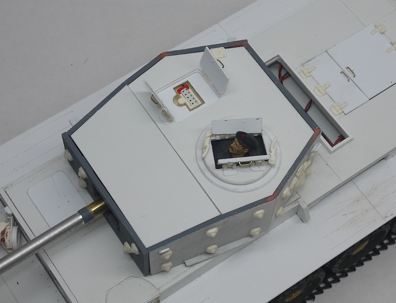
I changed the turret layout . I decided to make the whole assembly accessible by pulling everything out through the front mantlet. This is necessary as the rest of the turret will be glued up tight when done.
The pictures show the finished assembly , and how it will slid in through the front, and then the mantlet is attached to the turret by flush mounted screws underneath the turret.
I have been designing this as a go, and I just want to show you what my workbench looks like when I don't have a plan. Measure cut, trail run, until I end up with something that works.

") (okay, mines not much worse). Beautiful work!
11-10-2014, 06:10 PM
(okay, mines not much worse). Beautiful work!
11-10-2014, 06:10 PM
#16
Senior Member
Join Date: Jan 2011
Location: Bochum, GERMANY
Posts: 492
Likes: 0
Received 0 Likes
on
0 Posts
Hehe
i m not alone. My workbench looks mostly the Same lol.
i m realy happy what are you doing out of my kit. Going a complett own way to get it running. Thats the way i have made it for.
Cu christian
i m not alone
. My workbench looks mostly the Same lol.i m realy happy what are you doing out of my kit. Going a complett own way to get it running. Thats the way i have made it for
. Cu christian
11-10-2014, 08:20 PM
#17
Senior Member
Thread Starter
Join Date: Nov 2006
Location: Grande Prairie,
AB, CANADA
Posts: 8,976
Likes: 0
Received 4 Likes
on
4 Posts
Thanks Chris. I am enjoying building your kit. The drive wheels are also very nice. Building this Cromwell has been fun.
Tonight I cut the battery box out of the Heng Long chassis, to make more room for the electronics. This will have a Speaker, 15 watt amp and an Exciter. That is the next phase of the build process. I will get all the sound and mechanical stuff tested before I start on the finer details. The Benedini has a real nice RR Meteor engine sound.
Tonight I cut the battery box out of the Heng Long chassis, to make more room for the electronics. This will have a Speaker, 15 watt amp and an Exciter. That is the next phase of the build process. I will get all the sound and mechanical stuff tested before I start on the finer details. The Benedini has a real nice RR Meteor engine sound.
11-12-2014, 09:35 PM
#18
Senior Member
Thread Starter
Join Date: Nov 2006
Location: Grande Prairie,
AB, CANADA
Posts: 8,976
Likes: 0
Received 4 Likes
on
4 Posts
With the battery box removed it allowed me to space out the electronics as needed.
The Low profile gears have a tray mounted above them. This serves as a gear oil splash guard, and an electronics tray. Amp and power converted have been added here. Volume control will be accessible through the rear engine hatch
Audio set up is a TBS, 15 watt amp, and a power inverter to run 12 volts to the Amp. Speakers include a traditional 2X3 and an audio exciter mounted below the main electronics board.
Tank will have headlights, tail iights with brake light function, and a spot light..
I test ran this tonight and enjoyed the Meteor sound file. Next project to work on will be the lighting features


 .
.
The Low profile gears have a tray mounted above them. This serves as a gear oil splash guard, and an electronics tray. Amp and power converted have been added here. Volume control will be accessible through the rear engine hatch
Audio set up is a TBS, 15 watt amp, and a power inverter to run 12 volts to the Amp. Speakers include a traditional 2X3 and an audio exciter mounted below the main electronics board.
Tank will have headlights, tail iights with brake light function, and a spot light..
I test ran this tonight and enjoyed the Meteor sound file. Next project to work on will be the lighting features
 11-13-2014, 04:49 AM
#20
Yup! I too like it Dan, but you knew that already. We need (and I like) more British tanks. I have a Firefly and maybe a III or A4 in the works right now, but it's not as British as this is.
Love the sprocket and roadwheels work... it gives that authentic look plus the sound will make this a winner!
I'm envious!
Jeff
Love the sprocket and roadwheels work... it gives that authentic look plus the sound will make this a winner!
I'm envious!
Jeff
11-16-2014, 04:50 PM
#21
Senior Member
Thread Starter
Join Date: Nov 2006
Location: Grande Prairie,
AB, CANADA
Posts: 8,976
Likes: 0
Received 4 Likes
on
4 Posts
Work Continues on the Cromwell. This is requiring a lot of work. I am making molds and casting many detail parts in resin.
Played around with the sound files. Made A Battle Armor Cromwell sound set. I harvested Brad Pitts voice, and "Best Job I ever had" can now be played from the Cromwell.
Battle system is all in place as well.

 .
.
Played around with the sound files. Made A Battle Armor Cromwell sound set. I harvested Brad Pitts voice, and "Best Job I ever had" can now be played from the Cromwell.
Battle system is all in place as well.
11-16-2014, 05:27 PM
#22
Senior Member
Thread Starter
Join Date: Nov 2006
Location: Grande Prairie,
AB, CANADA
Posts: 8,976
Likes: 0
Received 4 Likes
on
4 Posts
Video. I know the Brad Pitts voices are a hokey effect, but it had to be done.
https://www.youtube.com/watch?v=dUO3XuLPbN0
https://www.youtube.com/watch?v=dUO3XuLPbN0
11-16-2014, 05:46 PM
#23

Awesome! I put my main battery along the centerline of my tanks but it does take up a lot of space, which means my control board and receiver have to be mounted vertically and to the side. Your setup is very neat with the battery to the side and the boards mounted flat!
Will there be any weight issues when running with the battery being positioned off the center line and aligned to one side?
Will there be any weight issues when running with the battery being positioned off the center line and aligned to one side?