


M4a1
 03-04-2015, 11:11 PM
#1

Thread Starter

I just finished up a power jam build session tonight. Went too late on it but when the mood is right you have to strike.
Last night I started by tearing apart a new HL metal upgrade M4A3 105 which I was simply going to convert to a 75W with a hobby radio, BARC3 IR and maybe recoil.
Ugh, here is where I went tonight.
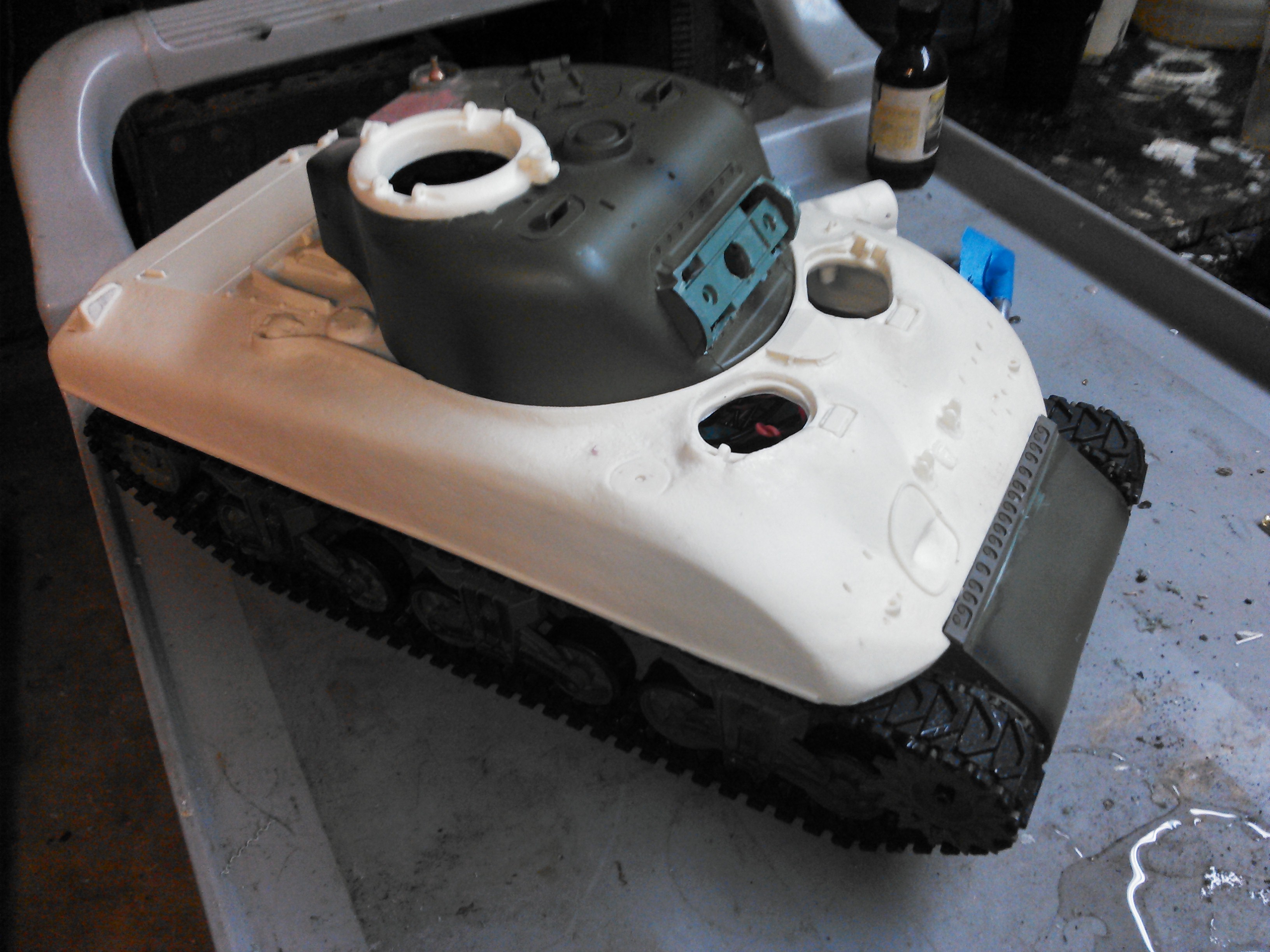
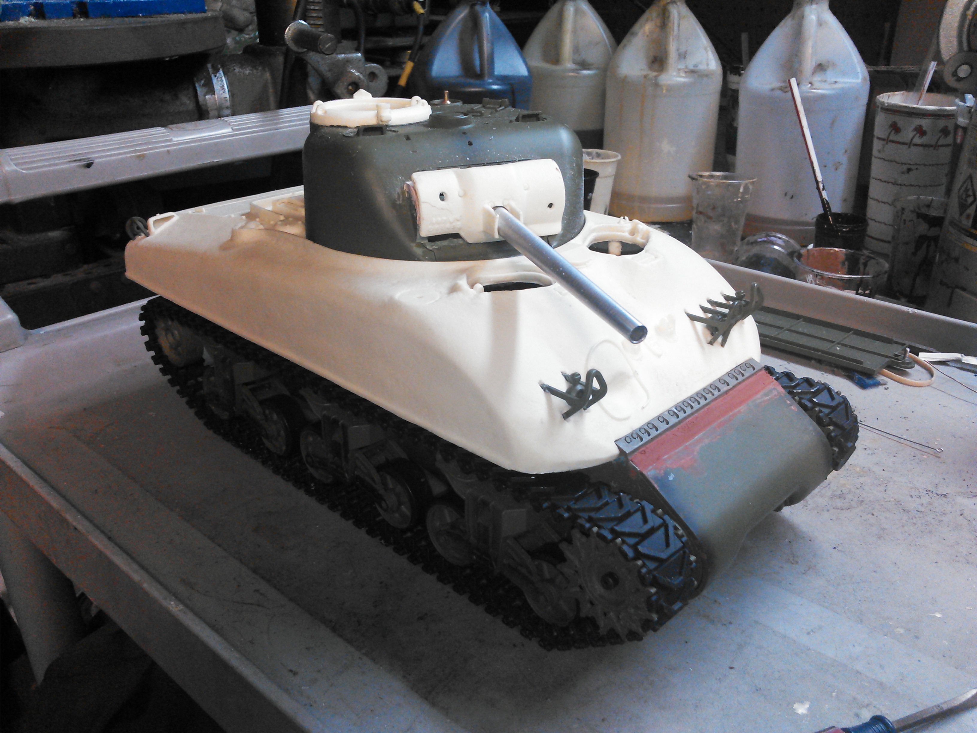
Urethane parts by Nick Aguilar. I am going to machine off the vision coupola and install an early split hatch. Also what you cant see is I leveled off the rear vent from the top of the bustle that only the 105 Howitzer model had. I will fill the hole with a blank out and putty it over maybe tomorrow.
Needed something to build while waiting for parts for Katy Cat, my EZ8 build, and not quite ready to build the 75 mount for the Half Track TD yet..
Last night I started by tearing apart a new HL metal upgrade M4A3 105 which I was simply going to convert to a 75W with a hobby radio, BARC3 IR and maybe recoil.
Ugh, here is where I went tonight.
Urethane parts by Nick Aguilar. I am going to machine off the vision coupola and install an early split hatch. Also what you cant see is I leveled off the rear vent from the top of the bustle that only the 105 Howitzer model had. I will fill the hole with a blank out and putty it over maybe tomorrow.
Needed something to build while waiting for parts for Katy Cat, my EZ8 build, and not quite ready to build the 75 mount for the Half Track TD yet..
Last edited by RichJohnson; 03-04-2015 at 11:25 PM.
 03-05-2015, 04:34 AM
#2
Looks good so far. Will be interested in your 75 halftrack build as well. Do you already have the mount and 75mm? I've got electronics coming my way for my Elmod M-16 board to be IR ready.
03-05-2015, 05:07 AM
#4
Some research materials for you:
http://the.shadock.free.fr/sherman_m...gehatches.html
Bob Held and I have pictures of the large hatch 75mm Sherman at the Port en Bessin museum if you need ref material for the DD conversion.
http://the.shadock.free.fr/sherman_m...gehatches.html
Bob Held and I have pictures of the large hatch 75mm Sherman at the Port en Bessin museum if you need ref material for the DD conversion.
 03-05-2015, 06:45 AM
#6
Is that bondo holding the brass tube in place? Bondo is one of the tools in my bag of tricks. It is easy to shape as it hardens.
03-05-2015, 06:51 AM
#7
Thread Starter
BennyB, I have a thread started on the half track conversion from a torro M16. Its a week or two back go look for it. No gun mount yet, just got my book with the cut aways for reference.
I have been living on the shaddock Sherman site lately doing research. I have two tanks in build and back burner plans for a Jumbo 76.
I came a cross some micro full rotation servos that will be coming my way that I am going to try for elevation. I am going to try to make a servo recoil as well, we'll see. I might result with a Tamiya, you never know.
Tonight, I am going to try to get the HL rotation system moved over, that is going to be the most challenging part of the project I believe.
You can never have too many Shermans.
03-05-2015, 06:53 AM
#8
Thread Starter
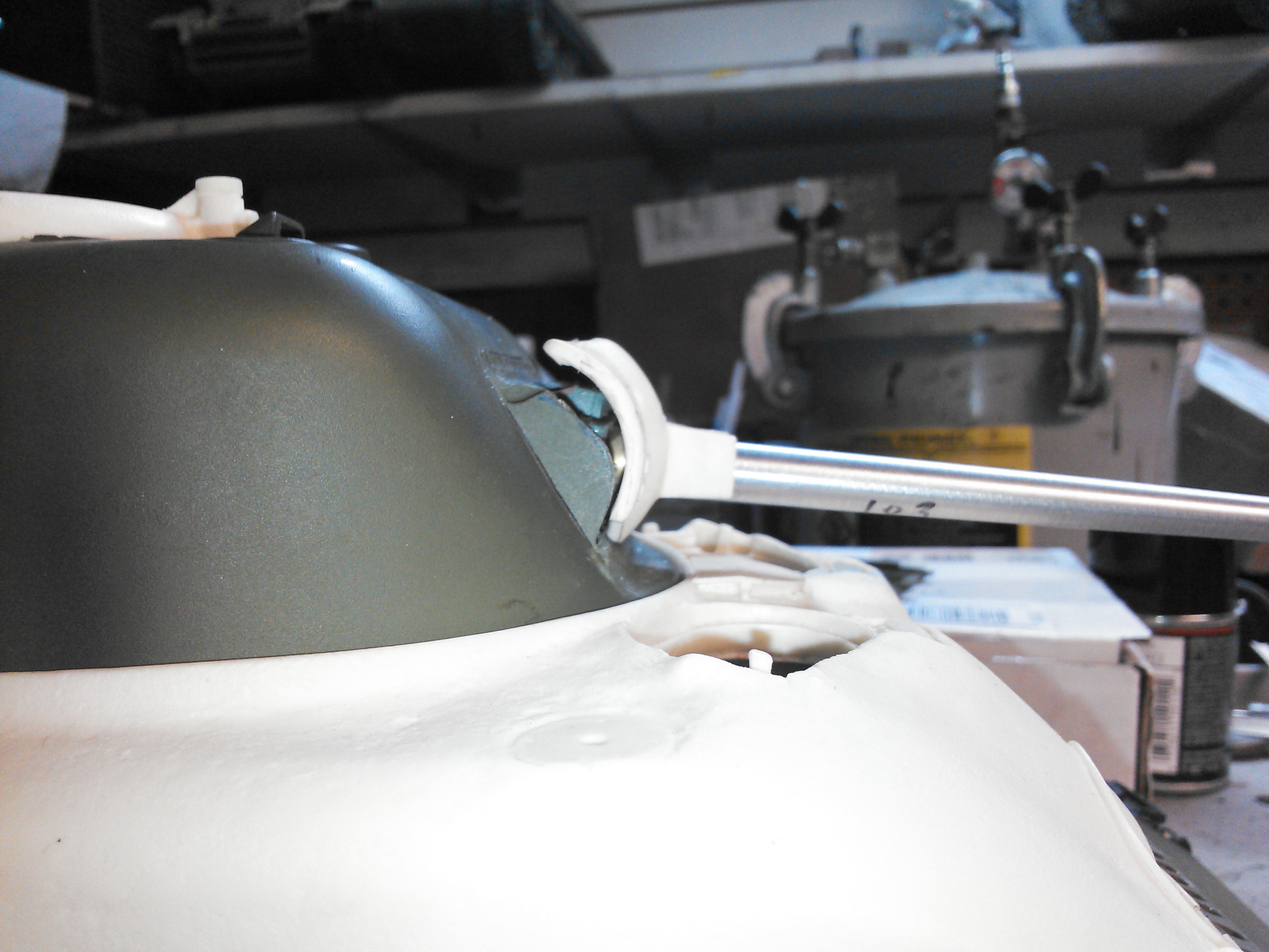
Yes it is bondo. Bondo is a great filler adhesive. I glued the barrel tube to the mantle and then began fitting it against the tilt mech on the HL turret. I had to oblong the hole in that part lower to get the mantle to line up on the turret, then I tacked it with CA let it dry, and filled the square cavity with bondo. I need it very strong, I have a baby that will probably get his hands on it.
03-05-2015, 04:22 PM
#9
Thread Starter
I have decided i cant stand the look of the mount for the gun, the mantle sticks off the casting on the turret way to far forward. In comparison of photos, the mantle should sit about half as close to the turret face. The curve of the casting gun mount should be much more shallow and gentle. Im going to take my new gun mount apart and file down the high curved castings of the 105 mount.
Just look hard at my middle photo in first post. Then go look at a 75 sherman photo broadside on google and my model will hurt your eyes.
Just look hard at my middle photo in first post. Then go look at a 75 sherman photo broadside on google and my model will hurt your eyes.
03-06-2015, 01:41 AM
#10
The 75mm should also sit a little higher in the turret than the 105 as well.
(altho I must admit that I left the pivot point where it was and just ground back the front like you have)
(altho I must admit that I left the pivot point where it was and just ground back the front like you have)
03-06-2015, 02:08 AM
#11
Another alternative is to buy the 75mm turret parts from the MATOMART Sherman parts page. I plan to do the same for some of my 75mms that have elevation issues. Many moons ago we cast some rotor shields and mantlets to do the conversion but I want to try the new stuff ASAP.
03-08-2015, 10:05 PM
#12
Thread Starter
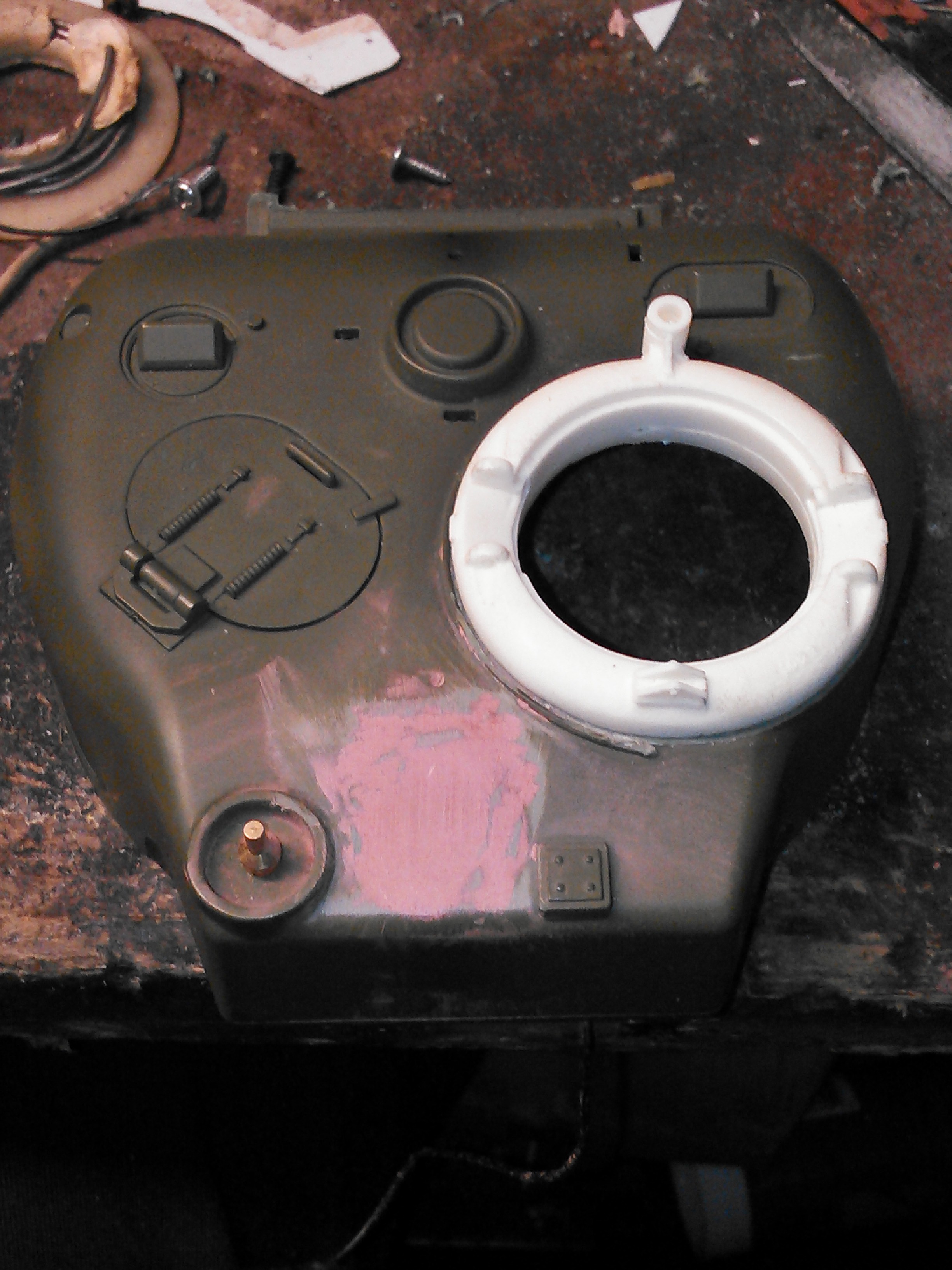
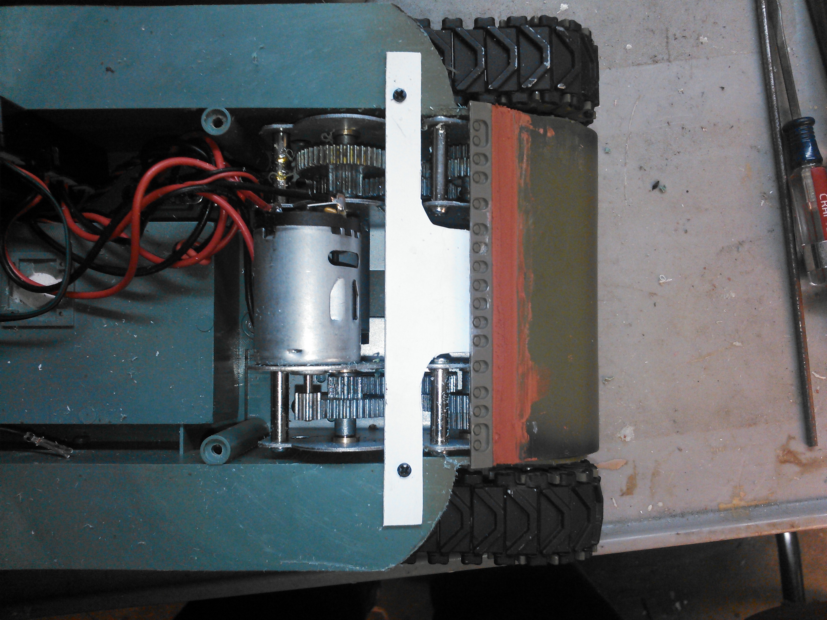
The HL turret is much smaller at the barbette than the Tamiya that Nick made his casting for, so the hole for the turret was huge. I coated the turret ring with lots mold relase along with the rotation gear and used bondo and built a barbette ring for the turret to rotate in. The turret rotates pretty well but is a tad sticky still in one spot so some more trim fitting or sanding is needed to get a nice clean guiding rotation. I have shim stock and plexiglass filled in the cavity of the under side of the engine vent where the rotation motor will mount, I have already test fit it there just need to drill screw holes.
The process of building up the bondo barbette was first I used just the turret and filled around it with bondo, then trimmed it for a good fit and smooth rotation. Then I screwed the gear onto the turret and pushed bondo between the new bondo barbette ring and the gear ring and built it up sold. Then removed the gear and trimmed down where it cast into the teeth.

The process of building up the bondo barbette was first I used just the turret and filled around it with bondo, then trimmed it for a good fit and smooth rotation. Then I screwed the gear onto the turret and pushed bondo between the new bondo barbette ring and the gear ring and built it up sold. Then removed the gear and trimmed down where it cast into the teeth.
Last edited by RichJohnson; 03-08-2015 at 10:22 PM.
03-11-2015, 06:11 AM
#13
Thread Starter
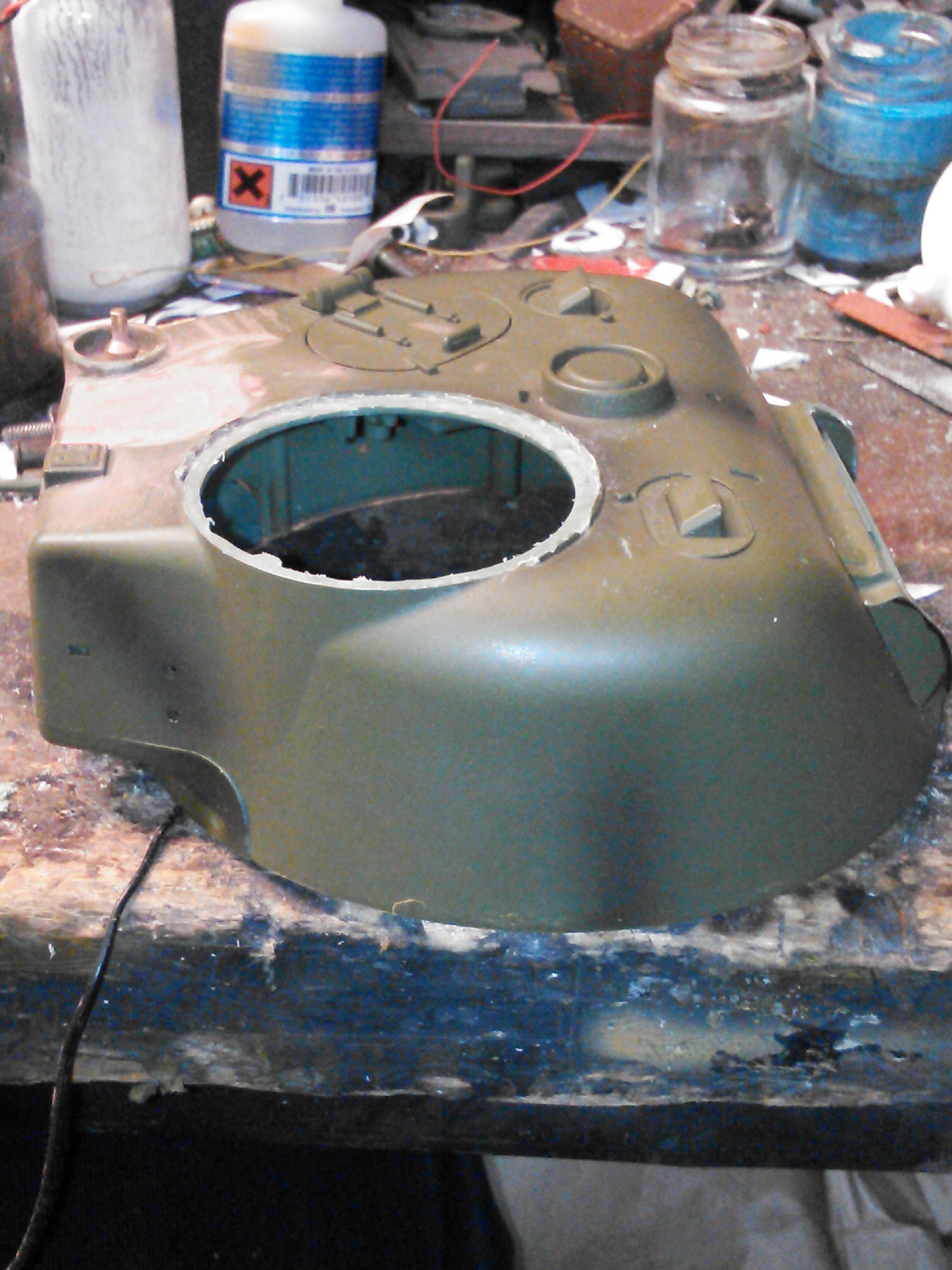
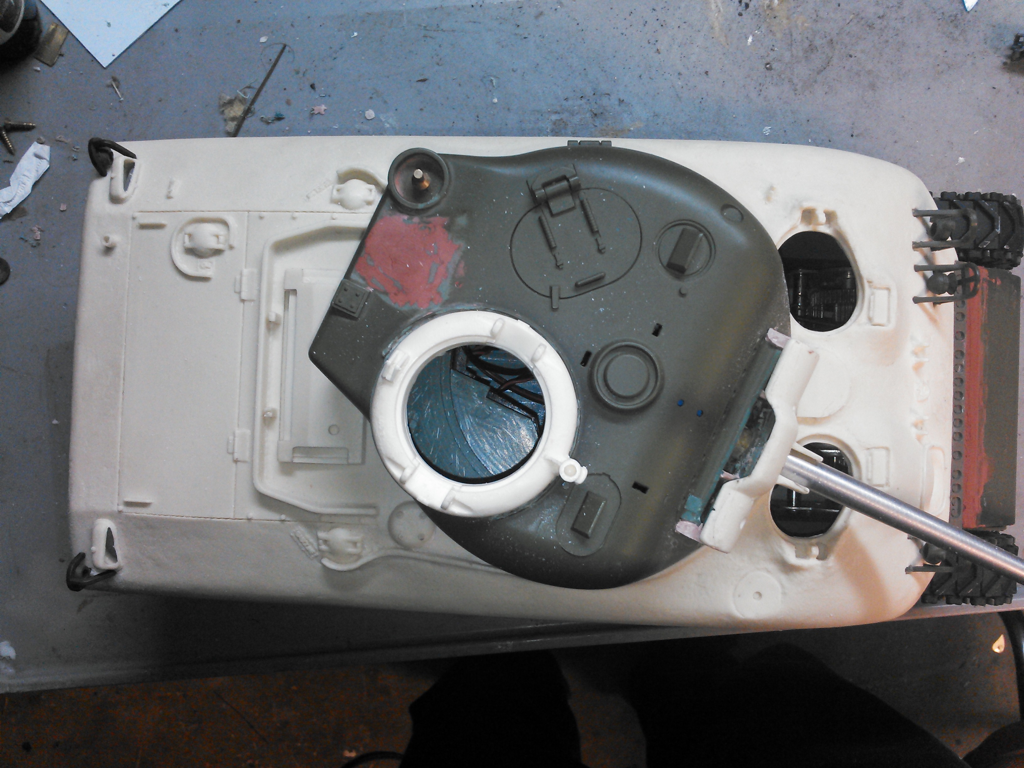
I finished cutting out the vision coupla hatch and machined off the edge for a clean surface to mount the split hatch onto.
On the rear I ground off the A3 door and puttied up the area to mount a Tamiya A1 door and air filters and exhaust pipes.
Up front I cut down the funky curve at the top of the transmission cover and glued on the Tamiya bolt bar at the top once I got it braced and fit in place where I felt it matched pictures. I still need to figure out a way to attach the cover at the top since I had to cut off the screw tabs that were there. Right now the cast hull sits kinda heavy on the cover and sags it down just a tad.
I would like to use the Tamiya hull clips, I have an extra lower hull clip but not the upper hull clip, I can make castings of these if anybody has an extra upper hull clip they could send me, Im not buying a couple trees of parts just for the clips.
03-12-2015, 10:59 AM
#14
Thread Starter
Last night I rebuilt the gun mount. I removed a lot of material from the 105 mount and yes it looks like hell right now but I will clean it up. My main concern was getting it closer to the turret face and keeping it elevating correctly. It was difficult to figure out where to remove material and I went real slow. I will go back and fill in the sides behind the mantle with bondo, and then remove what I would call the inside skirt behind the mantle, and make a new one top and bottom out of styrene so that you cant see through the mount when the gun elevates or lowers. Nick makes a wonderful accurate scale casting of this part, but I coundt figure out how to make use of it, and still have the pivot points for the elevation of the gun, so I cobbled this together using the HL pivots. Lots more work to do to the gun mount yet.
I also mounted the Tamiya air filters, I used the stock tabs and drilled them and glued the tabs in place in the hull.
The last part I made was an experimental strap to mount the top of the transmission cover. More on that later once I try it out.

I also mounted the Tamiya air filters, I used the stock tabs and drilled them and glued the tabs in place in the hull.
The last part I made was an experimental strap to mount the top of the transmission cover. More on that later once I try it out.
03-13-2015, 07:03 AM
#15
Thread Starter
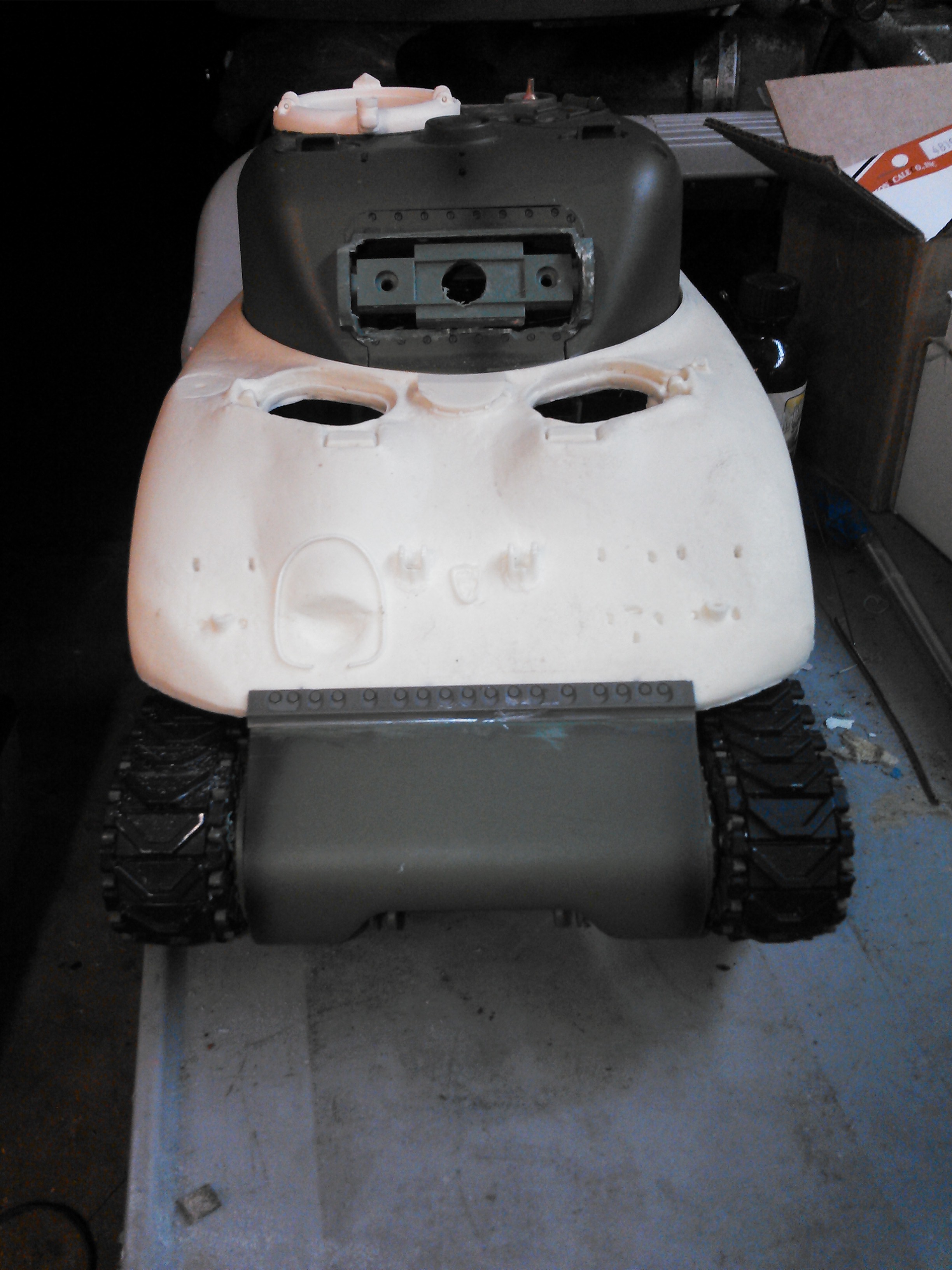
I got a lot done last night. I got the rotation motor drilled and screwed in place. I glued the rear engine door on. I also put some bondo behind the gun mantle to fill that nasty chewed up void I created. I finished my T bracket to hold the top of the transmission cover in place as well.
Then I started to extract the hull details off the HL M4A3 hull. I kept dabbing styrene cement on the inside of the hull on the tabs that were glued in then jabbed around them with an exacto knife and then when they got loose pushed them out with a tiny screw driver. 100% success, didn't break any of them and took about an hour to do. Then I drilled and ground out the A1 cast hull to make them fit. Next I think will be the LED lighting.
Im not sure if I should mount the commanders hatch with the gun pedestal facing forward or backward. Anybody got opinions either way?
03-13-2015, 07:20 AM
#16
Senior Member
Join Date: Dec 2012
Location: littlestown, PA
Posts: 758
Likes: 0
Received 0 Likes
on
0 Posts
I'm curious to see what you do for fenders. I got my jumbo hull with a broken fender and NOTHING seems to bond these two back together.
The best solution I can come up with is making them brass and attaching them to the lower instead of them being part of the upper.
As for your MG mount I'd leave it front facing and add the angle iron and pedestal to the rear.
The best solution I can come up with is making them brass and attaching them to the lower instead of them being part of the upper.
As for your MG mount I'd leave it front facing and add the angle iron and pedestal to the rear.
03-13-2015, 07:59 AM
#17
The uper hull looks further back than it should be? I compared photo 5 in post #13 to photo 3 in post #15 and it looks like you moved the upper hull back and extended the transmisson housing about a 1/4" to meet it?
03-13-2015, 08:35 AM
#18
Thread Starter
Maus you are sharp! I wasnt going to say anything and see if I could sneek the rework by you guys.
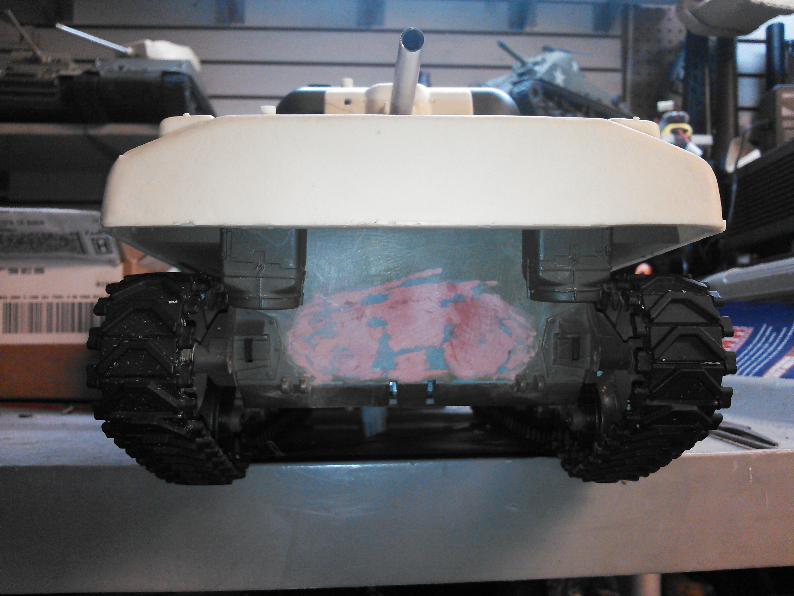
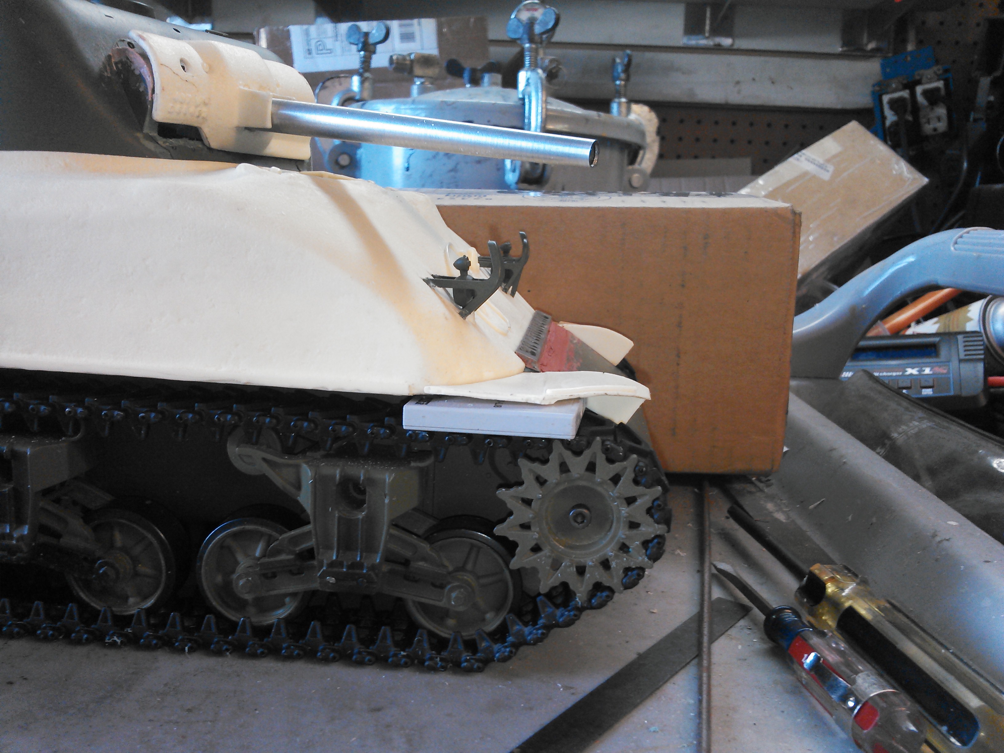
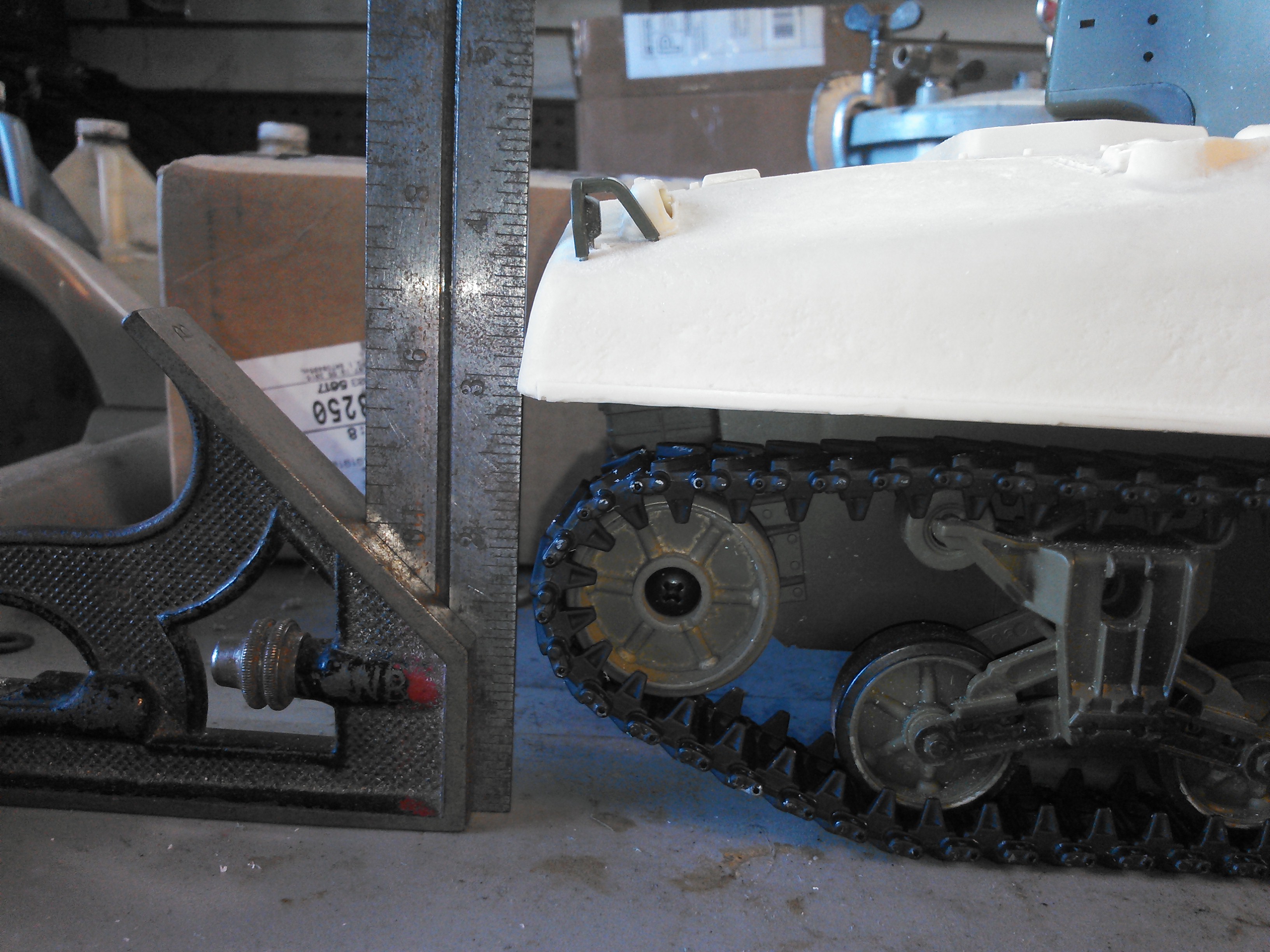
I noticed yesterday that the rear of the tracks hung out behind the rear edge of the hull. That didnt seem right to me so I did a bunch of photographic research as well as looked over some profile line drawings. Comparing the rear edge of the hull agaisnt the rear curveature of the track and where the slope of the front upper hull lines up with the drive sprocket. Gauging with a square, I needed to move the hull back as I did. The rear hull should just hang past the edge of the track a smidge. Belive me, I wish I hadnt had to, it was delicate work to redo my tranny bolt bar without jacking it up, but I am gald I did, an error like that would have bugged me for ever and probably forced me to sell the model because I cant look at my own work with an error like that.
Rusty, Nick's hull came with fenders. I just got a jumbo from him in the mail yesterday too. CA works very well to glue the urethane, ivebeen doing that for years, including my own urethane kits I used to make. If you need extra parts, as Nick if he can sell you some replacements.
03-13-2015, 09:52 AM
#19
Senior Member
Join Date: Dec 2012
Location: littlestown, PA
Posts: 758
Likes: 0
Received 0 Likes
on
0 Posts
I have the fender but since it's a battle tank it will just break again and again.
I like what you have done here. I would love to build a cast hull Firefly IC.
I like what you have done here. I would love to build a cast hull Firefly IC.
03-13-2015, 10:25 AM
#20
Thread Starter
Ooh Rusty, that sounds fun, but I already have the next couple builds lined up. Im taking a break after this one and work on the M3 TD if the pictures come in.
Now you have me thinking about the fenders, i wonder if they can be recast in a rubber material. Brass sheet might also be viable, i never thought about them getting beat up. A mechanical attachment like screws or tabs would be much better than glue. Im going to ponder this one. Maybe my supplier has OD color rubber....
if you do an A1 firefly, you would need a small hatch hull with welded or cast applique on the sides. This is a cast hull large hatch 75. There were only like 100 of these made before the turret switch to the T23 76mm. I wonder if Nick makes an older small hatch cast hull?
i really wish he would make a website just showing his products and prices, I keep after him on it.
03-13-2015, 10:58 AM
#21
Senior Member
Join Date: Dec 2012
Location: littlestown, PA
Posts: 758
Likes: 0
Received 0 Likes
on
0 Posts
Fender wise I am thinking about making them attached to the trans cover cargo board. This way they can be screwed into that giving them the support they need.
Last night I was bending some old antenna wire and thought about fixing them to the lower hull but don't think I like that as much as the first idea. BTW my lower is tamiya making it a tad harder.
Last night I was bending some old antenna wire and thought about fixing them to the lower hull but don't think I like that as much as the first idea. BTW my lower is tamiya making it a tad harder.
03-13-2015, 12:54 PM
#22
Rich, I am not rivet counting, just noticed the difference and thought the fenders up front would be long. HL must have made their lower hull a little longer? Your Sherman still looks great.
03-13-2015, 01:18 PM
#23
Thread Starter
Well, I am rivet counting, something like this issue is important to me. The large hatch hull is a bit longer than the older small jatch hull, the rear also slopes down a bit and is straight across as opposed to the verticle and U shape of the older hull. Also, the large hatch hulls picked up the track block mounts on the rear corners and the cargo frame across the rear. Going by pictures, I could be slightly off, at most, the hull lines up with the rear edge of the track, if im right, and its real hard to tell, the hull hangs past the track just a hair. I guess what I need to do is mount the fenders and see how they line up up front. Now is the time to fix the tranny cover if i need to take 1/16 inch out of it, but thats it, cant cut out any more.
03-13-2015, 04:36 PM
#24
Thread Starter
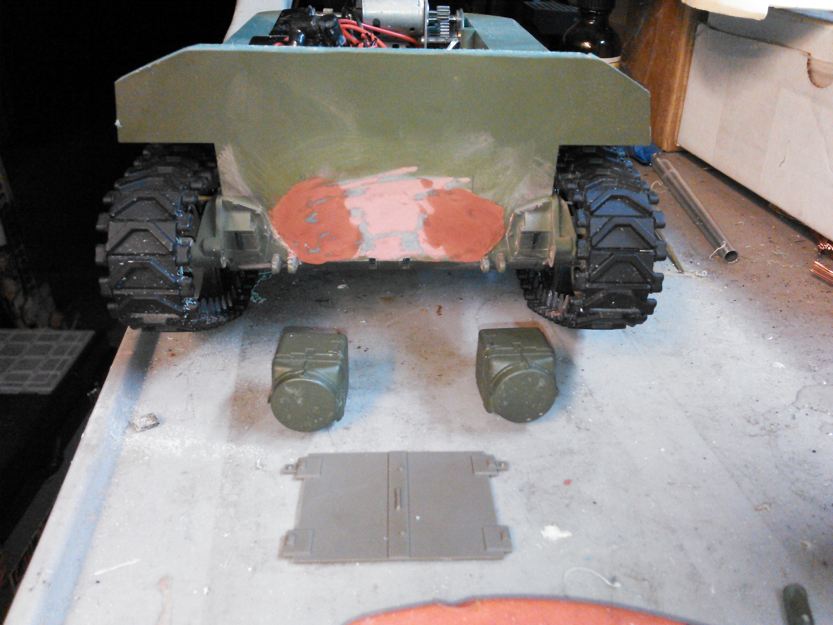
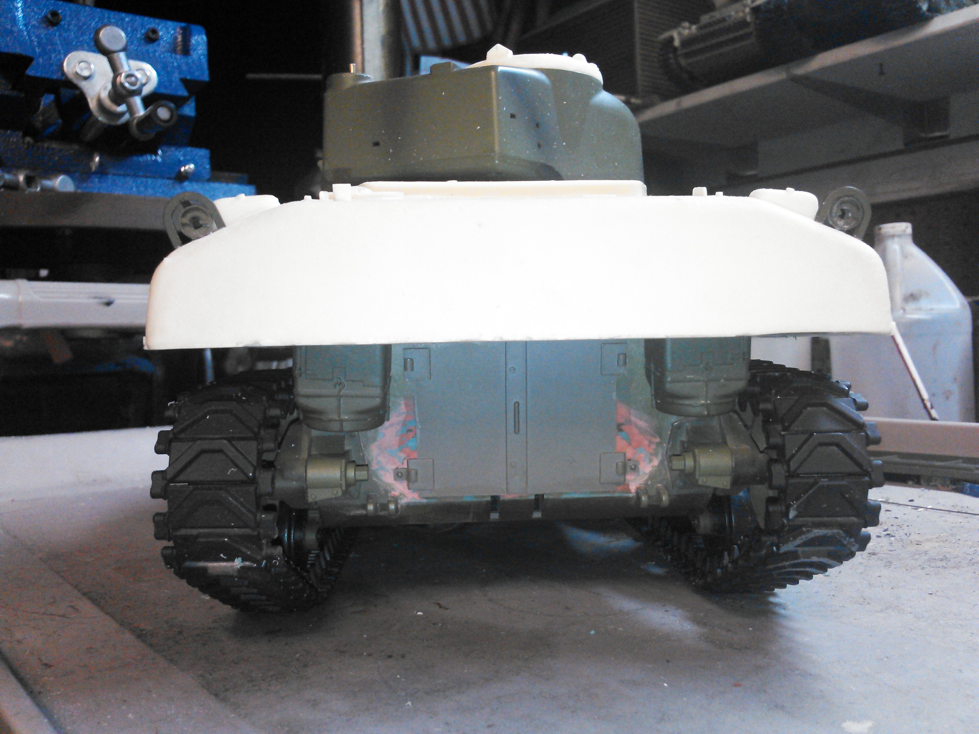
Ok, I set the fenders in place, and measured the edge of them to the front edge of the transmission and it was .2 of an inch. I took the same measurement on my stock Tamiya, exactly the same, .2 of an inch. So, I think it got it right. Here are some pictures.
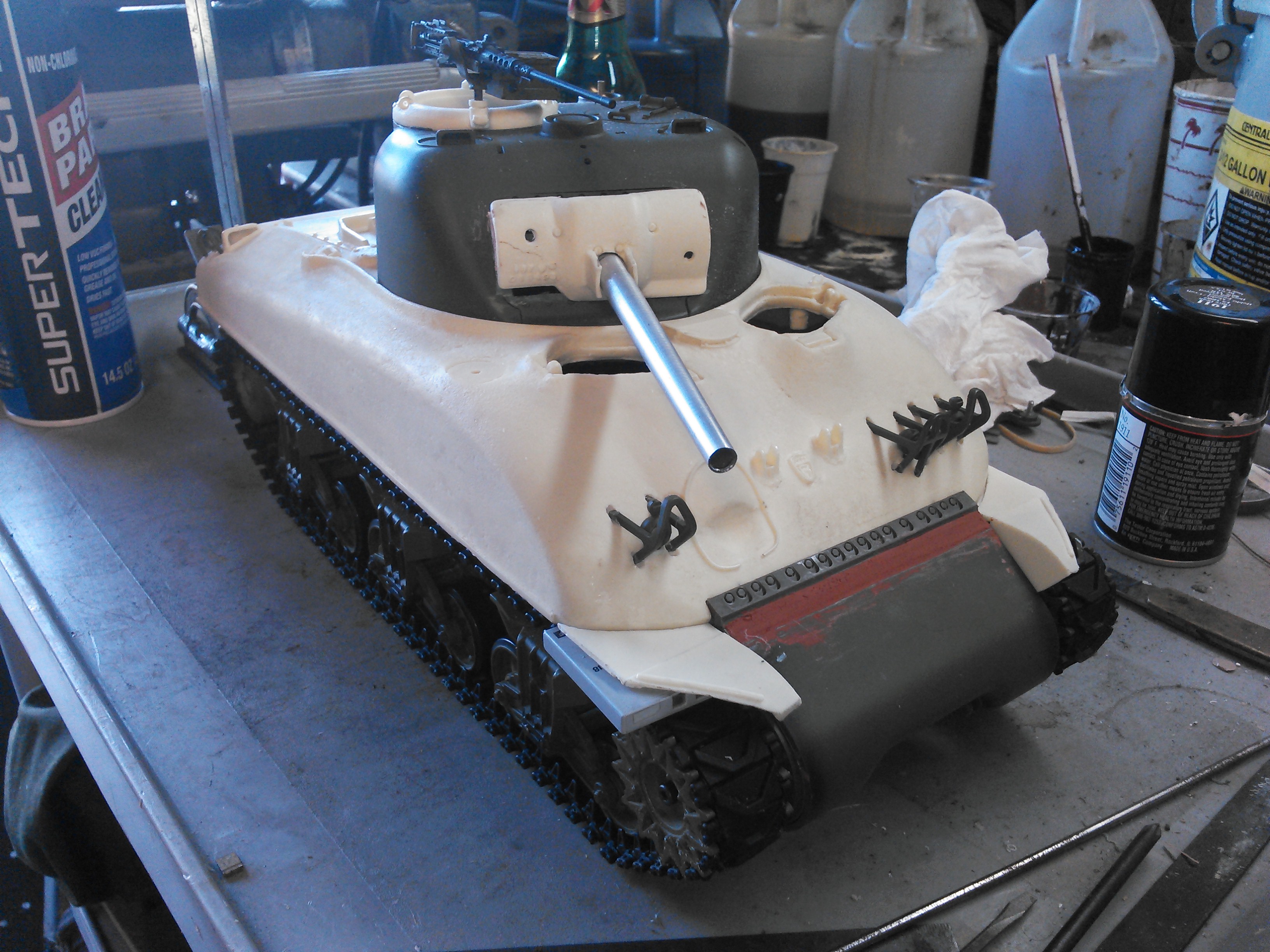
I also got my micro servos in the mail. Man are they tiny. The continuous one should work well for elevation. Well see what I can do about recoil.
I also got my micro servos in the mail. Man are they tiny. The continuous one should work well for elevation. Well see what I can do about recoil.
03-13-2015, 04:41 PM
#25
Looks good with the fenders in place.