


I'll be busy for a while....
 12-09-2016, 11:50 PM
#26

Thread Starter
Thanks for the kind words gents...
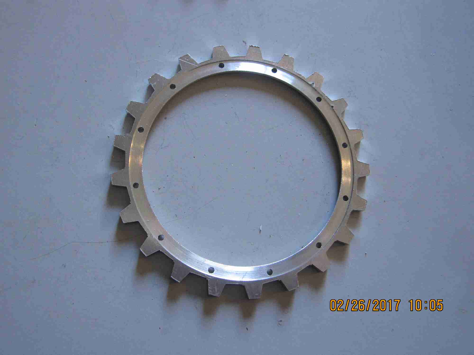
Made a trial of 4 sprocket rings, discs so far. Enough for two sprockets or one tank. I might be able to use two sets of the original castings I have.
Making the rings isn't terribly difficult but just a bit tedious.
See the results below, they still need a touch of hand work clean up and of course to be cut into actual rings...
Jerry
Last edited by Tanque; 12-09-2016 at 11:53 PM.

 01-19-2017, 07:39 PM
#28
Thread Starter
Between rain storms I was able to cast up a few parts for this project and make progress...
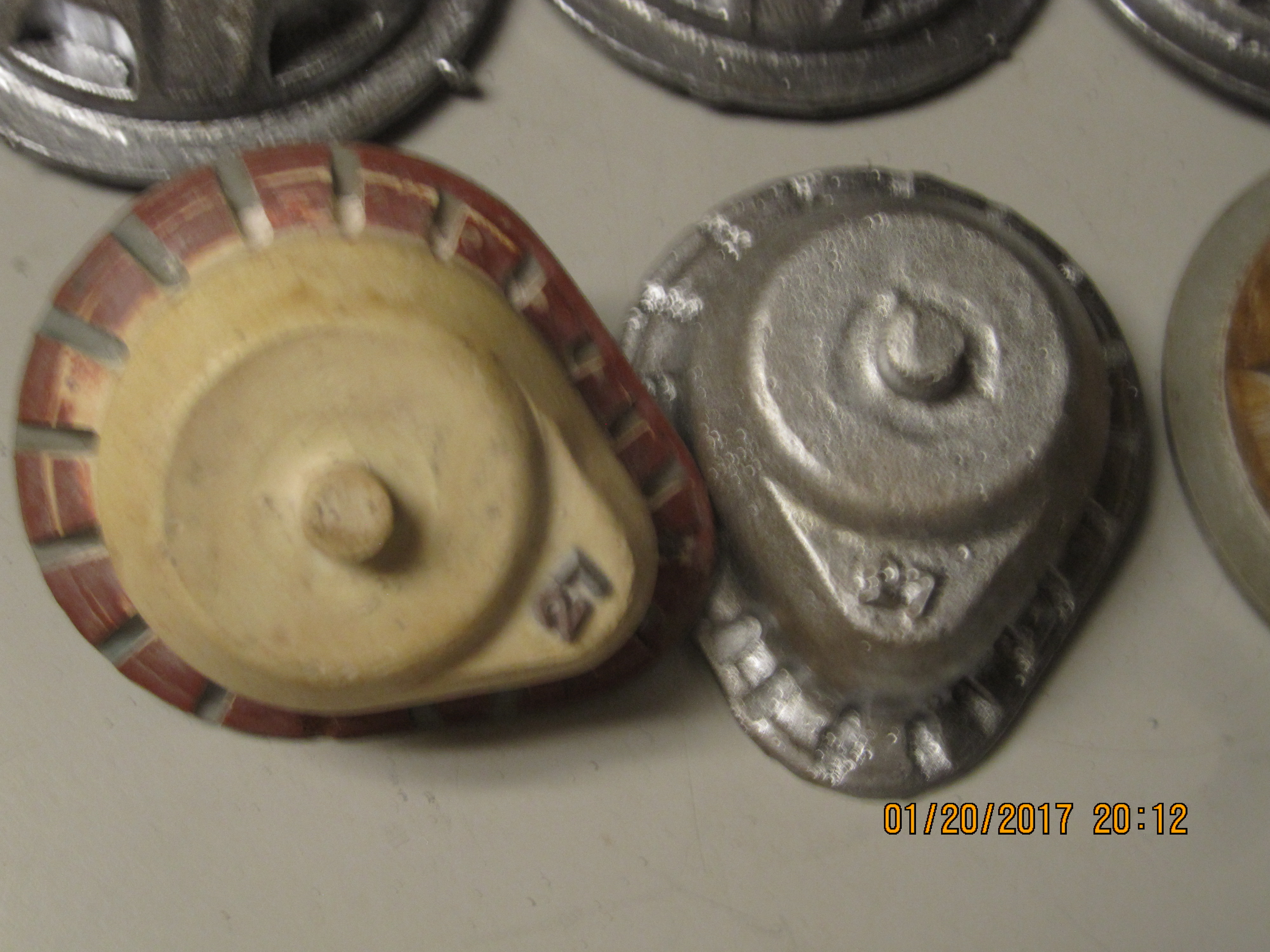
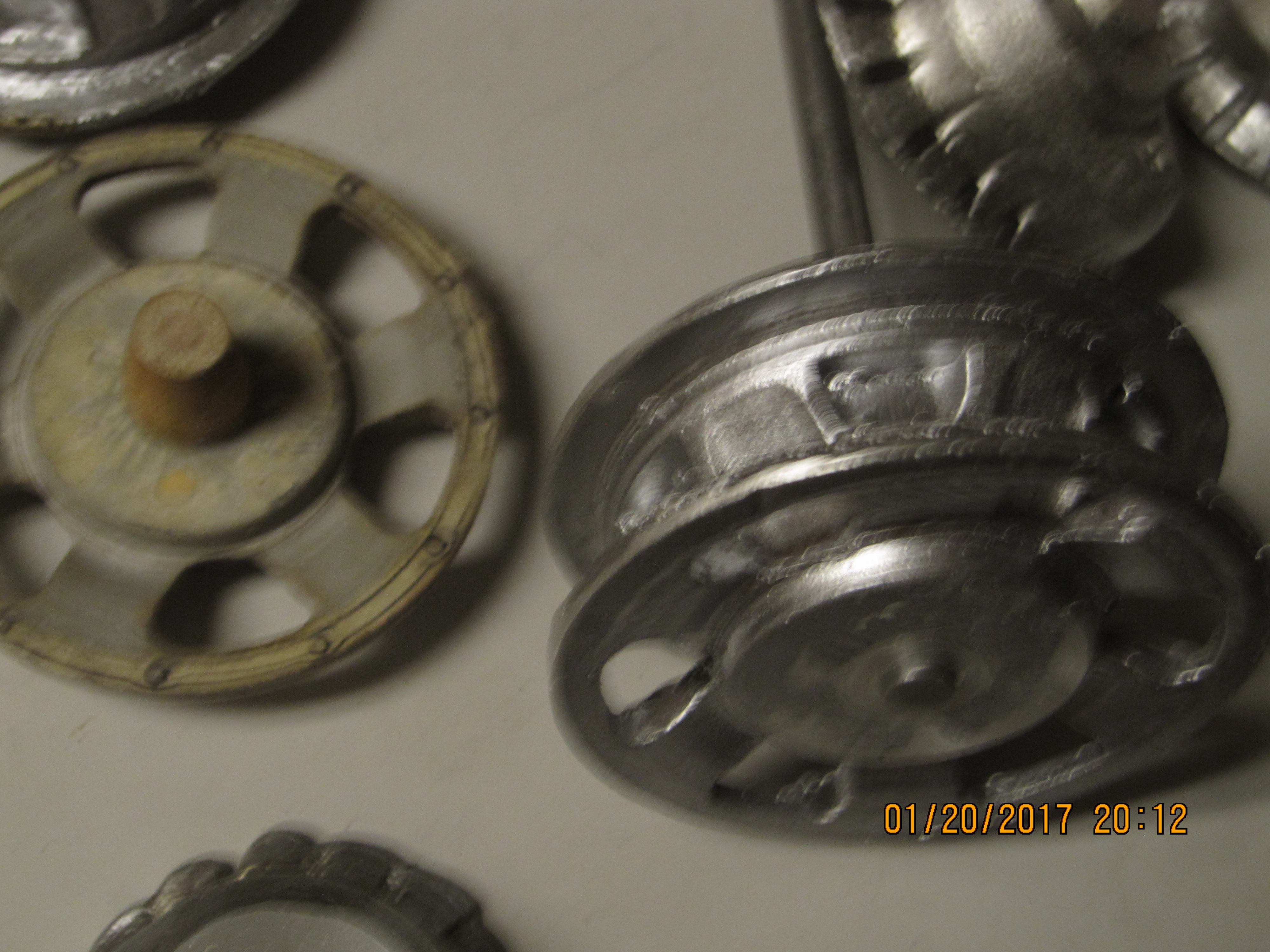
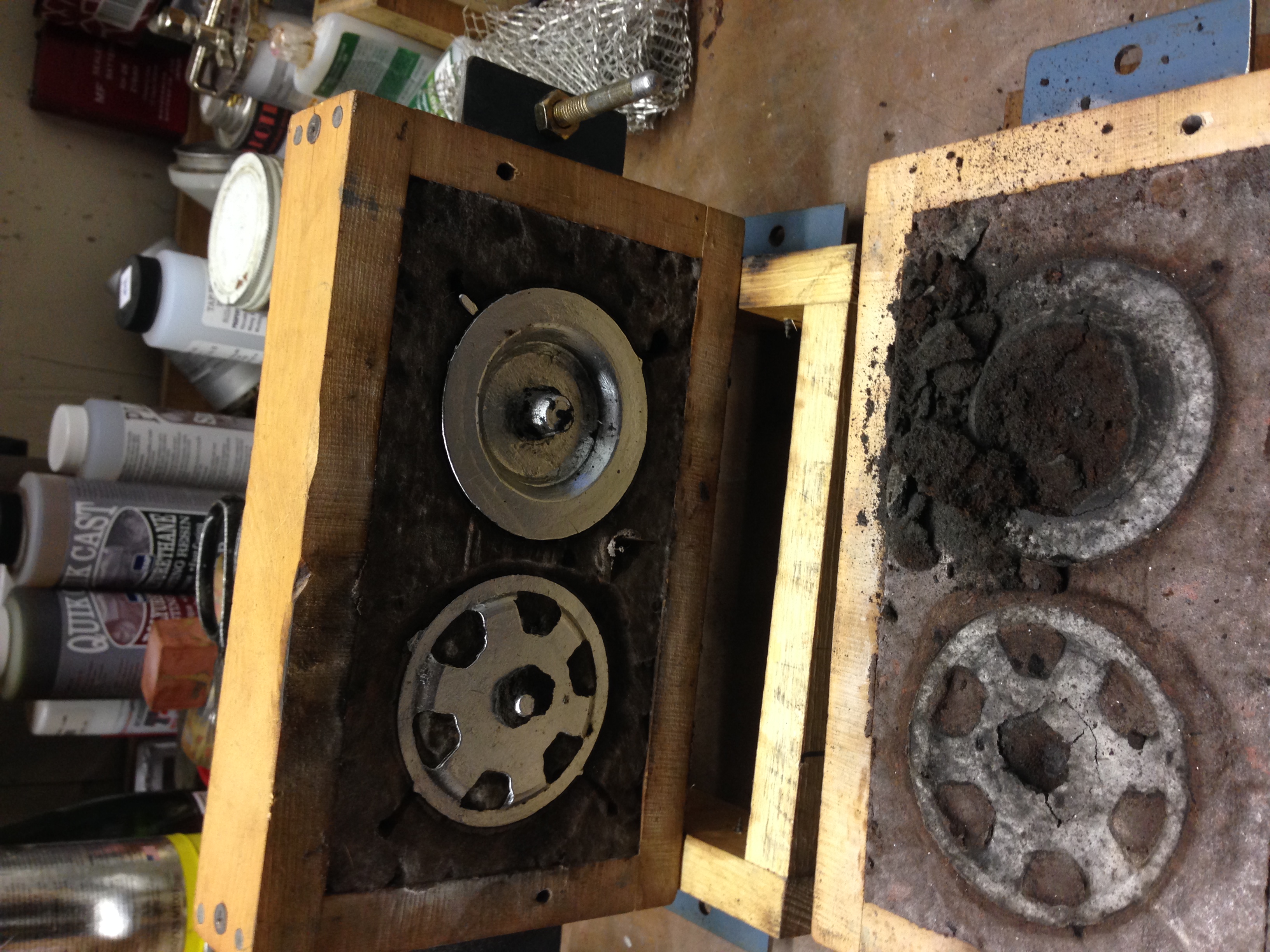
You can pick out the patterns in the attached photos. The back sprocket portion pattern is mostly
wood with a plastic flange ring. The front ( outer) portion of the sprocket body is plastic with attached wood pieces. The one final drive pattern is cast resin ( with lead numbers) and a polystyrene flange extension to aid
the pour. I've been making good use of my sand muller and it really makes a difference in the quality of the castings when you use properly prepared sand...
Jerry
01-19-2017, 07:48 PM
#29
Thread Starter
....more....
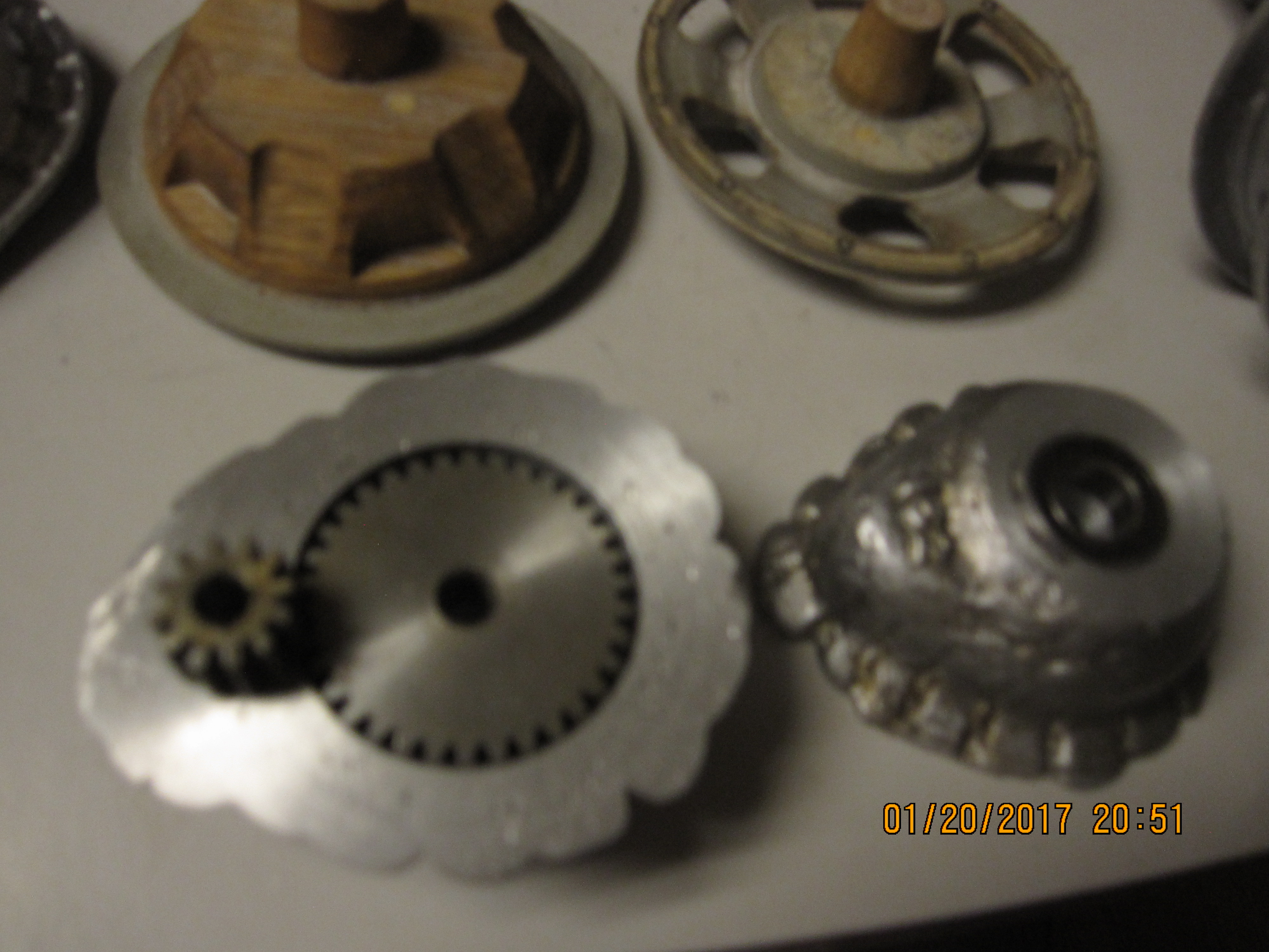
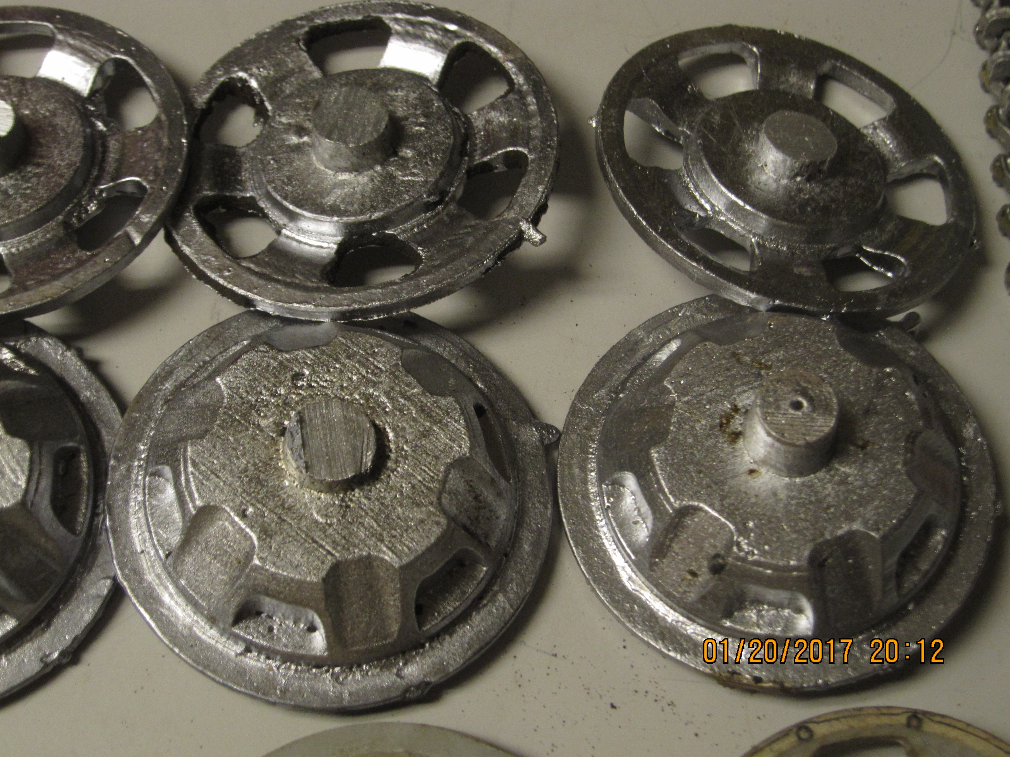
The first photo is of some pretty rough parts I used as experiments; rough but
sound parts. The flange as you see it on these is quite jagged. This is due to
me using this part before I had fixed on a larger sprue- metal just didn't flow into that thin area
before cooling. As you see from the later parts that was resolved. However... all I wanted
was a uniform pour- most of the flange will be removed as the original didn't have such a wide one
as you may see from the photos below.... jerry
Last edited by Tanque; 01-19-2017 at 07:56 PM.
02-11-2017, 11:59 PM
#30
Thread Starter
Haven't had a chance to work on these for a while. I decided that it would be safer to work on the sprocket rings if
I could mount them in a fixture that wouldn't crush them so I made on that I could easily and with reproducible result hold them in my lathe chuck while machining them to the usable dimensions.


I wanted to get an ideal if the assembled sprocket runs true so I put the assembly in my lathe ..
https://youtu.be/tBa5Jl1jZ5U This is just preliminary, there's much to do to finish this.
Jerry
I could mount them in a fixture that wouldn't crush them so I made on that I could easily and with reproducible result hold them in my lathe chuck while machining them to the usable dimensions.
I wanted to get an ideal if the assembled sprocket runs true so I put the assembly in my lathe ..
https://youtu.be/tBa5Jl1jZ5U This is just preliminary, there's much to do to finish this.
Jerry
02-26-2017, 12:39 AM
#31
Thread Starter
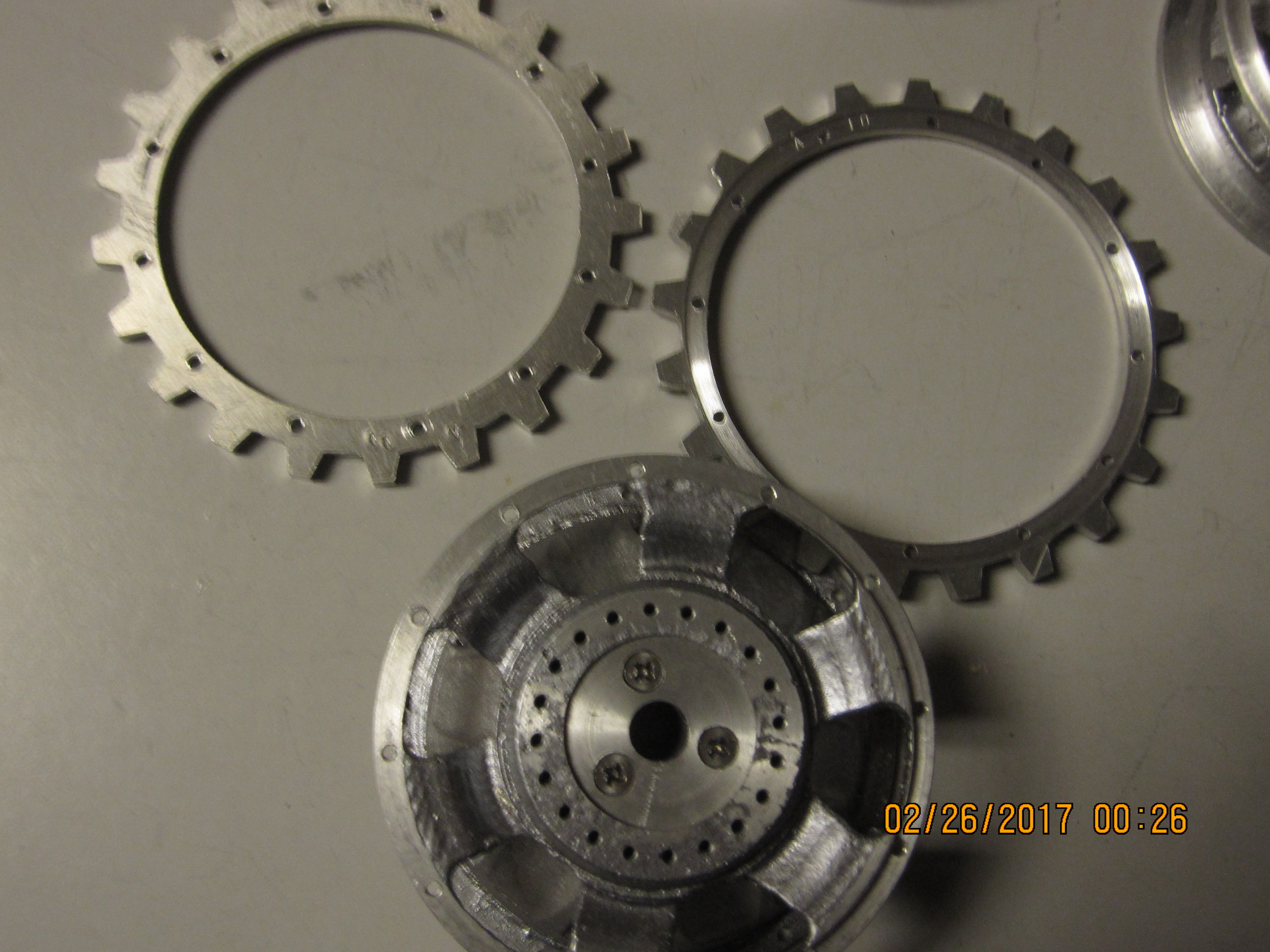
I've had a bit of time to apply to making my sprockets. In truth it is slow going. It's ticklish work and that's not restful. One twitch of a handle or too aggressive
on the cutting rate and much time is wasted. Unfortunately I found that when I cut the toothed disks, specifically the last group I was too aggressive when I
drilled the mounting holes around the circumference. In an attempt to trim some time and make the disks uniform in order to line up the teeth easier when mounting the resulting rings on the sprocket bodies I had drilled several disks at once.. Not the best idea. The small, #50 drill 'wandered' a bit and about half the disks have the holes too close to the outer edge. Can't really see it on casual inspection but it makes a number of disks quite useless from a functional standpoint so I'll likely use them as decorative items /spares on the models. I recall seeing a few photos of tanks that had spare sprocket rings in their stowage.
Also I purchased a number of steel sprocket disks from which to make rings from Martin at Geisswerk. I needed these to work with his tracks as they are
too tough on aluminium rings and happily they will engage properly with either the aluminium or bronze alloy track sets I'll be using. And they have the advatage of better wear and strength. Strength of my aluminium rings is a concern, they seem ok but they are quite thin by themselves.
BTW I was asked about what I'm going to do about the three non scale-like Phillips head screws in the middle of the sprockets. Either I will countersink them a bit further and seal / cover them with JB weld or similar or I will replace them with aluminium screw-rivets and make them disappear..
So the progress continues...

Jerry
on the cutting rate and much time is wasted. Unfortunately I found that when I cut the toothed disks, specifically the last group I was too aggressive when I
drilled the mounting holes around the circumference. In an attempt to trim some time and make the disks uniform in order to line up the teeth easier when mounting the resulting rings on the sprocket bodies I had drilled several disks at once.. Not the best idea. The small, #50 drill 'wandered' a bit and about half the disks have the holes too close to the outer edge. Can't really see it on casual inspection but it makes a number of disks quite useless from a functional standpoint so I'll likely use them as decorative items /spares on the models. I recall seeing a few photos of tanks that had spare sprocket rings in their stowage.
Also I purchased a number of steel sprocket disks from which to make rings from Martin at Geisswerk. I needed these to work with his tracks as they are
too tough on aluminium rings and happily they will engage properly with either the aluminium or bronze alloy track sets I'll be using. And they have the advatage of better wear and strength. Strength of my aluminium rings is a concern, they seem ok but they are quite thin by themselves.
BTW I was asked about what I'm going to do about the three non scale-like Phillips head screws in the middle of the sprockets. Either I will countersink them a bit further and seal / cover them with JB weld or similar or I will replace them with aluminium screw-rivets and make them disappear..
So the progress continues...
Jerry
03-02-2017, 10:38 PM
#33
Thread Starter
A variation on the sprocket is Gei�werk's stainless steel sprocket ring. I bough a number of his "blanks" (laser cut SS disks)
to use with his bronze alloy tracks. I cut two, enough for one sprocket this evening. This marks the 5th sprocket I've assembled
however there's much more work to be done and I need 5 more. I need to schedule a casting session to make more sprocket body parts.
Jerry

to use with his bronze alloy tracks. I cut two, enough for one sprocket this evening. This marks the 5th sprocket I've assembled
however there's much more work to be done and I need 5 more. I need to schedule a casting session to make more sprocket body parts.
Jerry
04-23-2017, 11:29 PM
#36
Thread Starter
I seem to only work on my pz III project fairly late at night and consequently I proceed slowly. In all fairness there are so many parts
to be thought out and then executed with not an inconsequential amount of tedium. It's slow going. Making up 10 sprockets from raw castings
and sprocket disks has taken a while. But happily now that part is mostly complete.
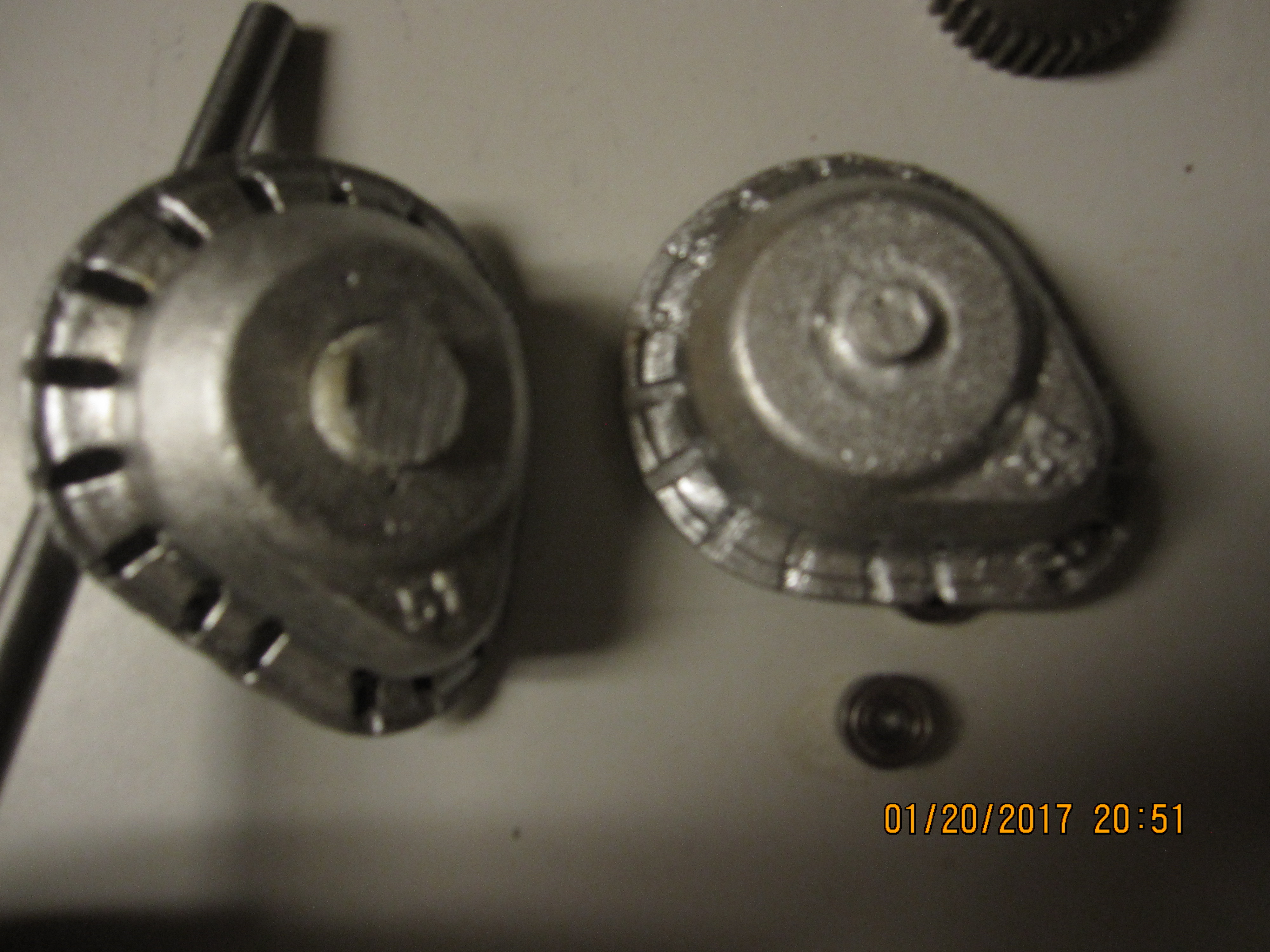
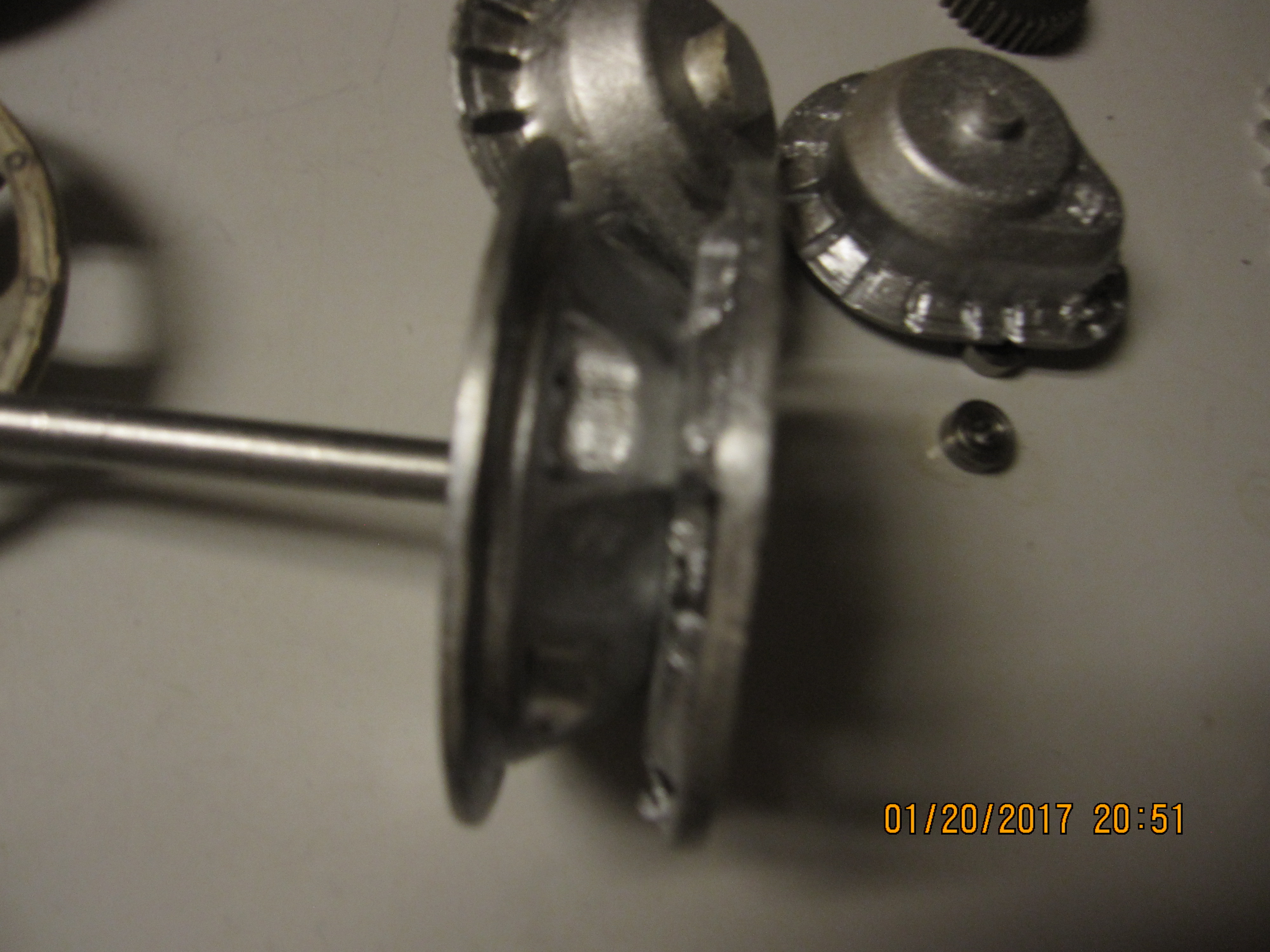
Next are the final drives. I'm still debating whether or not I want to make the final drives have an actual reduction gearing, I seem to
want to make extra work for myself. I'm asking the question 'what will 'functional' final drives actually buy me? Besides a certain amount of
coolness I'm not sure what the advantages would be. quite a few extra operations are necessary to get these to work. Below there are a few
photos of my trial piece.
The sprocket is held onto the output shaft by being attached to a retainer that is pinned to the shaft. The shaft has a Woodruf key slot cut
into it as does the larger gear have a corresponding key way cut - I was lazy and cut this one by hand with a jeweler's file but if I decide to make additional
units I will use a key way broach. I've not made it yet but envision a corresponding backplate with two bearings to support the two shafts. I envision this
plate being fastened to the inner side of the tank side plate, The central output shaft to which the sprocket is attached will only be long enough to just reach
the inner bearing. the shaft with the small pinion will extend past the plate and engage the transmission.
Stay tuned...
Jerry
to be thought out and then executed with not an inconsequential amount of tedium. It's slow going. Making up 10 sprockets from raw castings
and sprocket disks has taken a while. But happily now that part is mostly complete.
Next are the final drives. I'm still debating whether or not I want to make the final drives have an actual reduction gearing, I seem to
want to make extra work for myself. I'm asking the question 'what will 'functional' final drives actually buy me? Besides a certain amount of
coolness I'm not sure what the advantages would be. quite a few extra operations are necessary to get these to work. Below there are a few
photos of my trial piece.
The sprocket is held onto the output shaft by being attached to a retainer that is pinned to the shaft. The shaft has a Woodruf key slot cut
into it as does the larger gear have a corresponding key way cut - I was lazy and cut this one by hand with a jeweler's file but if I decide to make additional
units I will use a key way broach. I've not made it yet but envision a corresponding backplate with two bearings to support the two shafts. I envision this
plate being fastened to the inner side of the tank side plate, The central output shaft to which the sprocket is attached will only be long enough to just reach
the inner bearing. the shaft with the small pinion will extend past the plate and engage the transmission.
Stay tuned...
Jerry
07-04-2017, 11:02 PM
#37
Thread Starter
Still plugging away at my set of Pz III models. I've spent more time on the sprockets and final drive that just about anything else up to this point. So
many parts to work out and make. I redesigned the final drive housing patterns and recast them all. I made my own bearings either of brass or steel
and bronze. I decided that I want to emulate the original having a more or less a discrete separate final drive unit that is bolted in place on the lower hull.
I've attached a series of photos to capture this work; all yet a work in progress. The last two photos I realized are terribly out of focus so I apologize in advance.
Difficult for my point and shoot tp focus on these irregular objects; will try its big brother to try to get clear photos.
I did try the first final drive out, and it seems to work quite well.
07-23-2017, 05:42 PM
#38
Thread Starter
Jeese louise this website has become annoying... there are so many scripts launched and cookies being gathered it's a wonder we can even stay functional. to top it off I've started this
update 2 times already and the entry panel suddenly just wipes out all my input and I have to start over.... c'mon guys I know aderts make your world go 'round but sheese...
Anyway... I'm inching along with my Pz III work. I've made good progress on the final drives and I'm within a week or so of being able to mount them. I've included a photo of their current state
and a brief video of a test of one of the units using a cordless drill as power source. These units would have been a lot simpler and I'd have been done quite a while ago had I not insisted that the
drives have an actual 3:1 reduction. I used steel module 1 gears, 10 mm thick. There still some parts to make, circlips to install and clearances to check but they are close.
Jerry
07-24-2017, 02:39 PM
#39
Wow, love the test run of your final drive!!!
08-21-2017, 11:50 PM
#40
Thread Starter
Still plodding along. when I first attempted to mount the final drives on a model I discovered the shortcoming of my shortcut for mounting the
sprocket to the drive shafts. It was impossible to line up the 20 small( 1-72 ) screws/bolts to the sprocket shell. I had fabricated a steel flange which I pinned
to the output shaft and the holes for the 20 mounting screws were clearance holes which allowed the screws to wiggle and waggle anyway they wanted. Bad idea.
So I decided to make the parts I should have in the first place but hadn't as I knew they'd be hell a'devil to make. I had to thread 200 1-72 sized holes through 1/4" thick
aluminum so the screws would remain positioned correctly. Well I threaded those 200 holes and managed to not break a tap in the process. The initial test is good.....
Jerry
08-22-2017, 05:24 AM
#43
Nice to see them mounted!!!
08-26-2017, 06:13 AM
#44
Everything about your project is about a thousand or so times beyond my skill level. But the thing that almost gave me a heart attack and a stroke is this ------
"I had to thread 200 1-72 sized holes through 1/4" thick aluminum so the screws would remain positioned correctly."
The thought of ever having to do that gives me a brain cramp that could cause permanent brain damage (more than I already have).
rex
"I had to thread 200 1-72 sized holes through 1/4" thick aluminum so the screws would remain positioned correctly."
The thought of ever having to do that gives me a brain cramp that could cause permanent brain damage (more than I already have).
rex
08-26-2017, 08:14 PM
#45
Thread Starter
Everything about your project is about a thousand or so times beyond my skill level. But the thing that almost gave me a heart attack and a stroke is this ------
"I had to thread 200 1-72 sized holes through 1/4" thick aluminum so the screws would remain positioned correctly."
The thought of ever having to do that gives me a brain cramp that could cause permanent brain damage (more than I already have).
rex
"I had to thread 200 1-72 sized holes through 1/4" thick aluminum so the screws would remain positioned correctly."
The thought of ever having to do that gives me a brain cramp that could cause permanent brain damage (more than I already have).
rex
I believe the tap I started with is done as I'd used it quite a bit before I started these. I used a tap hole drill that was over sized by a bit as I wasn't shooting
for maximum strength rather than just enough engagement to keep the screw in line. As small as the screws are and as relatively long as the engagement surface is
it doesn't take a full depth thread to be plenty strong. To take part of the sheer boredom away I actually used my full sized electric drill to seat all 200 stainless screws and none
stripped out under that force so they are tough.
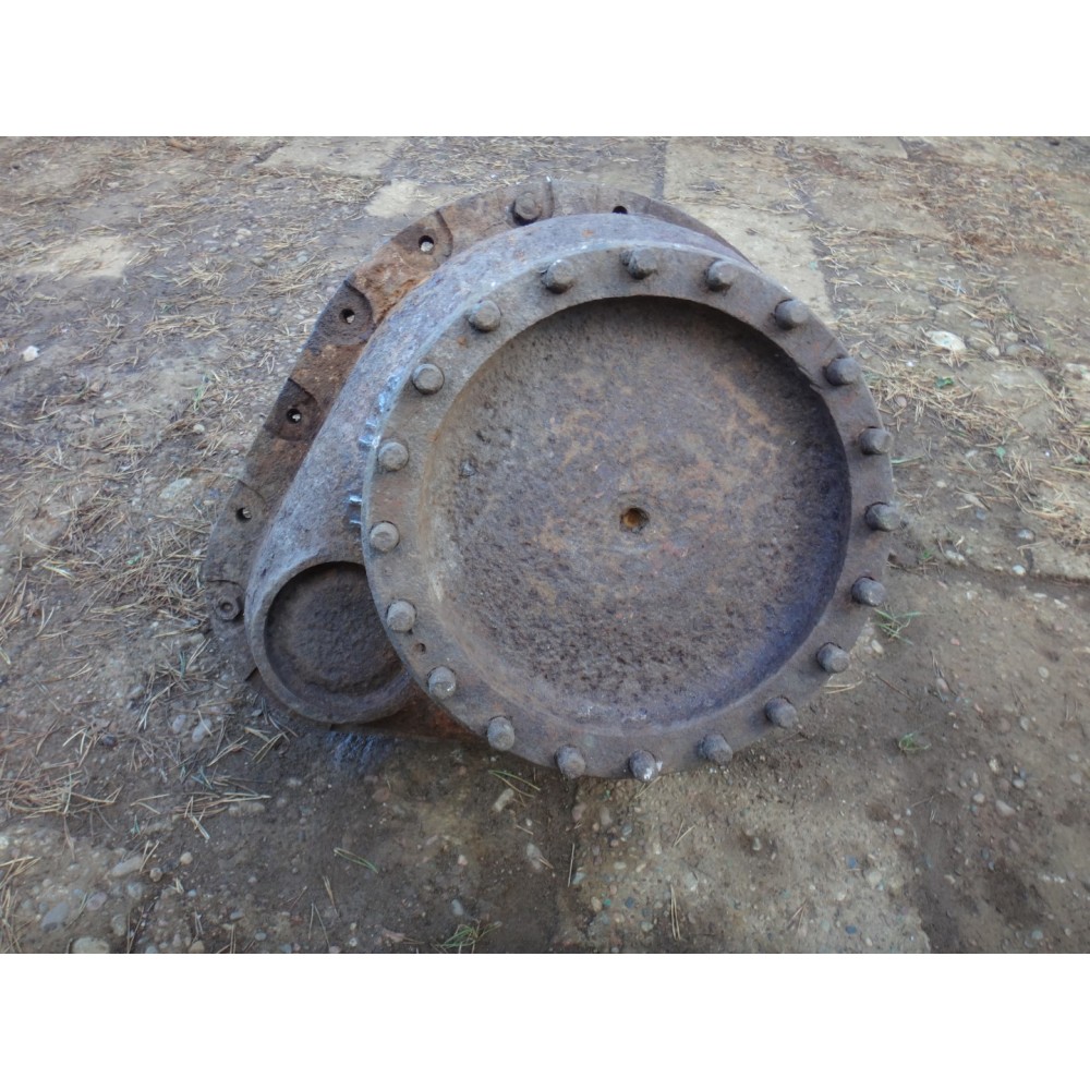
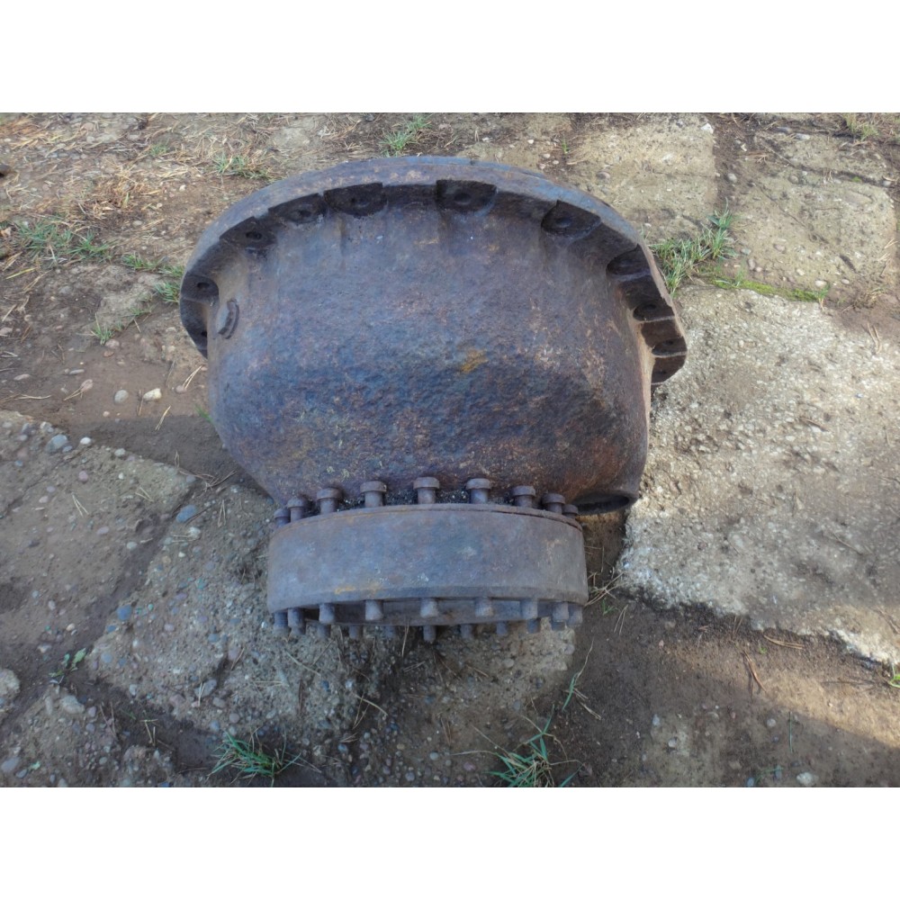
I'm convinced that 20 1-72 screws to fasten the sprocket to the drive output should be more than strong enough. A 1-72 screw is about 0.0730" ( 1.8mm) which works
out to about a 3/4" ( 18mm) bolt in full size and if you look at the image above of the full sized drive unit that seems pretty good. Probably a tad on the meaty side.
The core drive shafts are all 8mm steel. I've used 10 and 12mm for my larger models but I think 8mm will be sufficient for a pz III.
Right now I'm taking a rest from the sprockets and final drives and working on the idler rollers then to make the track tension adjustment mechanism.
Once I get these 5 models sitting on their own running gear I'll take a break from them to give me time to work out details, make a die to press road wheel caps, etc.
Jerry
12-09-2017, 06:13 PM
#46
Thread Starter
Hello all, it's been a while since I posted in this my thread on the construction of a series of panzer III variants.
I had originally posted a long winded reason why but decided to remove it! TMI!
Jerry
I had originally posted a long winded reason why but decided to remove it! TMI!
Jerry
Last edited by Tanque; 12-09-2017 at 06:22 PM.
12-12-2017, 12:44 PM
#48
Ditto, hope to see your progress with the Panzer III"s soon!!!!
12-12-2017, 05:50 PM
#49
Thread Starter
Thanks for the kind words gents. One major change in my life is that in October I retired from a 45 year career which for the greater part was as a software developer.
That by itself was a good move.
The one bad move was a more personal one. I didn't see something coming despite red flags and warnings from all, and I mean
all of my friends.. You know, or should know something is wrong when you begin to lose interest in things that have been part of your life
almost as long as air... I will get over it but it's going to take a while.
On a more positive note I have begun volunteer work on the USS Hornet ( CVS-12 ) over in Alameda, Ca - initially as part of the aircraft restoration group.
First project I'm involved with is the restoration of their F8 Crusader.
When I stopped working on the Pz III project I had just begun working out the adjuster mechanism and mounting system for the Idler wheels...now slowly but surely
I'm back on it..
Jerry
12-14-2017, 07:15 AM
#50
Wow, working with the USS Hornet sounds like a dream job!!! Sneaks some photos.