


Centurion Tank 1:16
 09-15-2016, 10:43 PM
#151

 09-16-2016, 09:30 AM
#152
Hi Longsheep
Worked on the ring last nite, used hot water to help with the bending, overlap of the ends 1-2mm
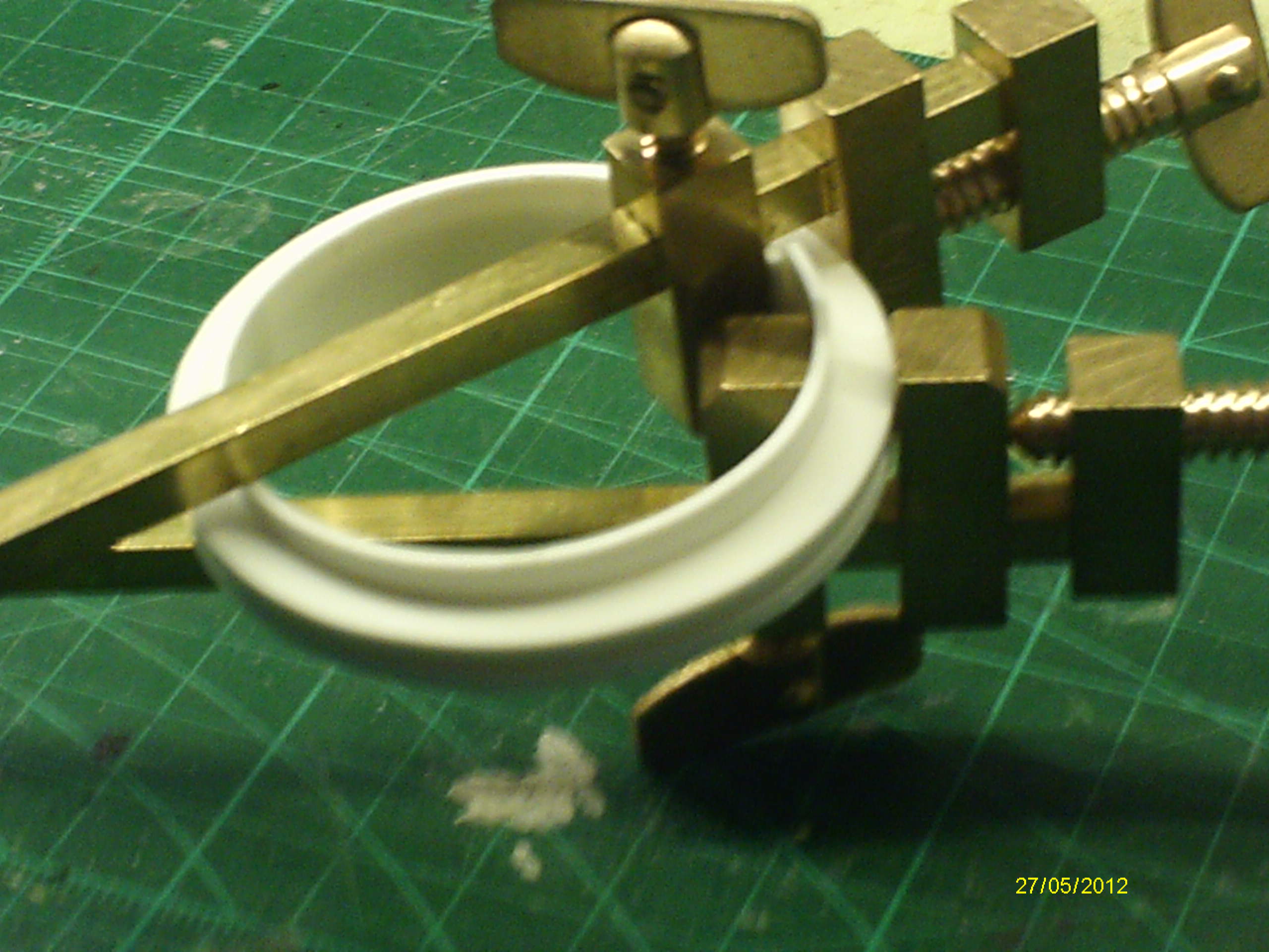
 Still have to trim the excess.
Do you have a source for that book - couldn't find anything on google?
Was aware that some of the parts are simplified - the final drives are essentially Tamiya part copies, the real thing is more like these, from Stephen Whites Armortek build
 The shot deflector in front of the Cupola should be heavily sloped
 rather than the squared block supplied in the kit
 but I guess that's what a file is for. Don't think I'll bother with the final drives, as they're well hidden, though could be a 3D print project for someone. No doubt there will be more simplified parts to deal with - if there weren't I suspect the cost would be way higher.
Mal
Worked on the ring last nite, used hot water to help with the bending, overlap of the ends 1-2mm
Do you have a source for that book - couldn't find anything on google?
Was aware that some of the parts are simplified - the final drives
Mal
I can also confirm that you won't see the final drive at all with drive sprocket on.
For the WWP book, here is the review: http://www.armorama.com/modules.php?...ontent&id=6618
You can order directly on WWP site I believe, they ship from Czech.
09-16-2016, 03:35 PM
#153
I like the Centurion,but the turret sure takes a lot of work to get it into the correct shape? Would it have been better to split it top and bottom instead of down the middle? I am not knocking it just want to understand the process?")
09-16-2016, 08:50 PM
#154
I think Chris/Freddy just followed the design of the Tamiya 1/25 Centurion kit. The removable roof allows you to access the components inside.
The turret was first 3D printed then cast in resin. The 3D print prototype was very straight and required little preparation, but costed around $200 alone.
For home/garage kit casting, it is far easier to cast left/right halves than top/bottom, as shallow, dish-shaped casts will give even more troubles.
09-17-2016, 01:55 AM
#155
Thank you Longsheep for your post 
You�re right about the technics we used, it was much easier to divide the turret vertically than horizontally. Chris told me that the forthcomming turrets will be better casted.
Freddy
You�re right about the technics we used, it was much easier to divide the turret vertically than horizontally. Chris told me that the forthcomming turrets will be better casted.
Freddy
09-17-2016, 02:11 PM
#156
Senior Member
Thread Starter
Join Date: Jan 2011
Location: Bochum, GERMANY
Posts: 492
Likes: 0
Received 0 Likes
on
0 Posts
hi
i m not sure if a horizontal split will help, so biger the part so more diverenz you wil get, so the vertikla split causes 2 smal parts. a horrizontal split would generet 2 biger parts and teoretikaly more problems by puting them togther. that was just the idee behind that.
cu christian
i m not sure if a horizontal split will help, so biger the part so more diverenz you wil get, so the vertikla split causes 2 smal parts. a horrizontal split would generet 2 biger parts and teoretikaly more problems by puting them togther. that was just the idee behind that.
cu christian
09-18-2016, 05:01 PM
#157
Join Date: Nov 2010
Location: HamiltonWaikato, NEW ZEALAND
Posts: 937
Likes: 0
Received 78 Likes
on
55 Posts
Interesting discussion. From mine it looks like the unsupported parts of the roof sag inwards. Maybe a fix is to support the parts until they fully cure?
Rec'd the missing parts - bearings, mantlet & bumper stops


The mantlet rear is pretty rough, note the male trunnions, which I removed, drilled 2.5mm holes & placed2.5mm X 12mm bolts to allow elevation & depression - though not much play either way Secured the cupola by drilling 1.5mm holes in the front outermost bolt holes & placing 1.2mm hex bolts
  cleaned out the main gun hole & drilled out the coax (3mm)
 Side by side comparison of Cent & M26 turrets
 Had a look at the sprockets, the teeth rings need to be bolted to the inner hubs
 But the inner hubs need to re drilled
 Tooth rings covered in plastic film. No nuts for the bolts - or are they just glued?
Mal
Rec'd the missing parts - bearings, mantlet & bumper stops
The mantlet rear is pretty rough, note the male trunnions, which I removed, drilled 2.5mm holes & placed2.5mm X 12mm bolts to allow elevation & depression - though not much play either way
Mal
09-18-2016, 09:40 PM
#158
Yes Mal, the mantlet is the roughest cast by comparison and takes some filing to fit. I just used brass tubings for the gun pivot, 8mm and 6mm ones I believe.
For the drive tooth rings, steel M1.2 x 6 (or shorter, you will have to cut short anyway) will be needed, about 50 in total. I received them in the package but not sure if they are in your too - I did order some extra screws from Chris. No gluing is needed and even just 8 screws per side will hold the ring firm, although I used about 20 each side to be sure. Be sure to reinforce the inner shaft mount of the drive wheel hub - it is pretty soft and gets lose after my first test run.
And below are videos of my first run! I pushed her 70% to smooth up the drive teeth and test for failures - 2 screws from alum base plate came off and the reinforced drive hub got loose. Working on them now.
HD videos here:
https://www.youtube.com/watch?v=3RayX8pJZCE https://www.youtube.com/watch?v=UB7C_5Oc8RE
For the drive tooth rings, steel M1.2 x 6 (or shorter, you will have to cut short anyway) will be needed, about 50 in total. I received them in the package but not sure if they are in your too - I did order some extra screws from Chris. No gluing is needed and even just 8 screws per side will hold the ring firm, although I used about 20 each side to be sure.
Be sure to reinforce the inner shaft mount of the drive wheel hub - it is pretty soft and gets lose after my first test run.And below are videos of my first run! I pushed her 70% to smooth up the drive teeth and test for failures - 2 screws from alum base plate came off and the reinforced drive hub got loose. Working on them now.
HD videos here:
https://www.youtube.com/watch?v=3RayX8pJZCE https://www.youtube.com/watch?v=UB7C_5Oc8RE
09-19-2016, 10:44 AM
#159
Thanks for the explanation, just wanted to understand the ins and outs of the casting process. I have always wanted to try my hand at casting parts.
09-21-2016, 04:40 PM
#160
Join Date: Nov 2010
Location: HamiltonWaikato, NEW ZEALAND
Posts: 937
Likes: 0
Received 78 Likes
on
55 Posts
Had a closer look at the 20 Pdr Type A barrel t comes with a 12mm ID pipe for the recoil
 Unfortunately the mantlet hole is only large enough for the bare barrel
 Rather than attempt to drill it out, I got a 12mm ID linear bearing - http://www.vxb.com/LM12UU-Linear-Mot...p/kit14013.htm -
 and bogged it in place
  Whether it'll work ... we'll see?
While I had the bog out, applied some to various places on the turret that I thought needed it


Hi Lonhsheep
So those bolts are just friction fit - no nuts? How did you reinforce the sprocket?
Mal
While I had the bog out, applied some to various places on the turret that I thought needed it
Hi Lonhsheep
So those bolts are just friction fit - no nuts? How did you reinforce the sprocket?
Mal
09-23-2016, 12:31 PM
#161
Had a closer look at the 20 Pdr Type A barrel t comes with a 12mm ID pipe for the recoil Unfortunately the mantlet hole is only large enough for the bare barrel Rather than attempt to drill it out, I got a 12mm ID linear bearing - http://www.vxb.com/LM12UU-Linear-Mot...p/kit14013.htm - and bogged it in place Whether it'll work ... we'll see?
While I had the bog out, applied some to various places on the turret that I thought needed it
Hi Lonhsheep
So those bolts are just friction fit - no nuts? How did you reinforce the sprocket?
Mal
While I had the bog out, applied some to various places on the turret that I thought needed it
Hi Lonhsheep
So those bolts are just friction fit - no nuts? How did you reinforce the sprocket?
Mal
For the barrel, I glued a 8mm aluminum pipe inside it and fitted it into a Clark recoil. The servo recoil was not affected by the rather rough mantlet drilling.
For the sprocket, M1.2 screws will self-tap inside the nylon hub firmly and the bond is likely stronger than the nylon itself. I reinforced the insides of the hub with some epoxy putty and glue.
That was after the stress run test made the sprocket loose from the drive shaft.
09-28-2016, 01:29 PM
#162
Join Date: Nov 2010
Location: HamiltonWaikato, NEW ZEALAND
Posts: 937
Likes: 0
Received 78 Likes
on
55 Posts
Hi LongsheepNot much build progress to report.
Cleaned up the turret after the bog session, applied anothercoat of WAJ


Spent a couple of hours cleaning up the suspension parts –grinding off the attachment points & peeling off the plastic film. Had toput each piece in the vice, twice – top & bottom, eventually did 2 at atime


Fitted bearings to the road wheels & idlers, strangelythe bearings fit perfectly on the back side of the wheels, but only 4 of 12 didon the front side. Still need to figure out how to fix those
Noticed the mantlet no longer elevates/depresses. Looking atit, the bog around the linear bearing lines up with the bolts in the turretfloor, preventing depression, so drilled a hole either side of the bearing & countersunk it, not a completecure


I’ve gained an appreciation for sprue & part numberingfrom this kit.
Do you have a pic of your spocket reinforcement?
Mal
Cleaned up the turret after the bog session, applied anothercoat of WAJ
Spent a couple of hours cleaning up the suspension parts –grinding off the attachment points & peeling off the plastic film. Had toput each piece in the vice, twice – top & bottom, eventually did 2 at atime
Fitted bearings to the road wheels & idlers, strangelythe bearings fit perfectly on the back side of the wheels, but only 4 of 12 didon the front side. Still need to figure out how to fix those
Noticed the mantlet no longer elevates/depresses. Looking atit, the bog around the linear bearing lines up with the bolts in the turretfloor, preventing depression, so drilled a hole either side of the bearing & countersunk it, not a completecure
I’ve gained an appreciation for sprue & part numberingfrom this kit.
Do you have a pic of your spocket reinforcement?
Mal
09-28-2016, 08:31 PM
#163
Hi LongsheepNot much build progress to report.
Cleaned up the turret after the bog session, applied anothercoat of WAJ
Spent a couple of hours cleaning up the suspension parts –grinding off the attachment points & peeling off the plastic film. Had toput each piece in the vice, twice – top & bottom, eventually did 2 at atime
Fitted bearings to the road wheels & idlers, strangelythe bearings fit perfectly on the back side of the wheels, but only 4 of 12 didon the front side. Still need to figure out how to fix those
Noticed the mantlet no longer elevates/depresses. Looking atit, the bog around the linear bearing lines up with the bolts in the turretfloor, preventing depression, so drilled a hole either side of the bearing & countersunk it, not a completecure
I’ve gained an appreciation for sprue & part numberingfrom this kit.
Do you have a pic of your spocket reinforcement?
Mal
I only added some epoxy putty to the sprocket hole and pushed the axle in, so it fills around the empty space inside the hole. I have no plan to take it apart for now with tracks on.
09-29-2016, 01:00 PM
#164
Join Date: Nov 2010
Location: HamiltonWaikato, NEW ZEALAND
Posts: 937
Likes: 0
Received 78 Likes
on
55 Posts
Inside? Didn't think there was room? Or do you mean where the cut out in the drive shaft sits?
Had been thinking you must have reinforced outside the hub & wondered how you'd done that, given the smooth curve of the hub.
Mal
Had been thinking you must have reinforced outside the hub & wondered how you'd done that, given the smooth curve of the hub.
Mal
10-03-2016, 03:49 AM
#165
I have been working on the gun and turret lately.
10-12-2016, 06:47 PM
#167
Join Date: Nov 2010
Location: HamiltonWaikato, NEW ZEALAND
Posts: 937
Likes: 0
Received 78 Likes
on
55 Posts
I'm about 2 weekends worth of progress behind in reporting, so.....
Applied another coat of WAJ (What A Job) to the turret, including thegun .
 Also applied it to the 3D printed sprockets, the 3d printed items tend tobe porous & soft, the WAJ fills the holes & leaves a hard surface


Spent time on the suspension – had thought to thread acouple of the screw holes to fit 2.5mm screws, but my tap & die setssmallest tap is 3.5 mm, so ended up just drilling out the centre holes to2.5mm. In order to do that, used 5mm screws to align the 2 halves for drilling.
Tried attaching the Pz III shock absorbers, got the femaleend fitted, but the male end doesn’t sit right


Applied WAJ to the rest of the 3D printed parts includingroad wheels & idlers & the final drive halves.
Finally assembled & applied glue to the lower hull,joined the final drive halves, glued the cupola ring & deflector to theturret roof & the roof ‘support rib’ to the underside of the roof


Repainted hull interior silver, turret interior, includingroof, hull decking interior


Mal
Applied another coat of WAJ (What A Job) to the turret, including thegun .
Spent time on the suspension – had thought to thread acouple of the screw holes to fit 2.5mm screws, but my tap & die setssmallest tap is 3.5 mm, so ended up just drilling out the centre holes to2.5mm. In order to do that, used 5mm screws to align the 2 halves for drilling.
Tried attaching the Pz III shock absorbers, got the femaleend fitted, but the male end doesn’t sit right
Applied WAJ to the rest of the 3D printed parts includingroad wheels & idlers & the final drive halves.
Finally assembled & applied glue to the lower hull,joined the final drive halves, glued the cupola ring & deflector to theturret roof & the roof ‘support rib’ to the underside of the roof
Repainted hull interior silver, turret interior, includingroof, hull decking interior
Mal
10-12-2016, 07:02 PM
#168
Join Date: Nov 2010
Location: HamiltonWaikato, NEW ZEALAND
Posts: 937
Likes: 0
Received 78 Likes
on
55 Posts
A bit more catch up.
Added the upper deck - not glued - though need to bend the sheet, just behind the drivers hatch
Decided to work on the gunners sight, seemed to spend a lot of time combing through my books looking for a close up of it.
Cut the pieces out of 2 different sheets – the base is thicker & on a different sheet. Got carried away & no pics of the assembly. It’s somewhat akin to two stacked boxes on the base, with a hole in the front of the bottom one
I wanted to add a ’glass’ vision block, so used a piece of 6mm thick acrylic rod – as permy M41 builds – but wanted it to penetrate the roof, so as to convey depth. SoI needed to cut a hole thru the base, then thru the roof plate and thru thesupport/attachment rib, which would otherwise obstru
Had to use the vice to squeeze in the acrylic block into thesight – very tight fit, and took a pic when finished, but you can’t see theacrylic
Also worked on fitting the roof of the turret –with the support/attachment rib glued in place, the roof no longer fitsprecisely, so had to trim part of the edge flange on the turret. Would havebeen better to have done this before gluing the rib to the turret – hindsight . Before
Up to date with where I'm at.
Mal
10-16-2016, 01:26 PM
#170
Join Date: Nov 2010
Location: HamiltonWaikato, NEW ZEALAND
Posts: 937
Likes: 0
Received 78 Likes
on
55 Posts
Hi Ad Lav
Elevation & Recoil? - haven't really decided, but have got some of the HL Stug elevation units & have Lego Rack & Pinion units too, so will try those first, though that might be a while.
Mal
Elevation & Recoil? - haven't really decided, but have got some of the HL Stug elevation units & have Lego Rack & Pinion units too, so will try those first, though that might be a while.
Mal
10-16-2016, 03:41 PM
#171
Join Date: Nov 2010
Location: HamiltonWaikato, NEW ZEALAND
Posts: 937
Likes: 0
Received 78 Likes
on
55 Posts
Worked on the turret components, assembled the cupola, added4 X 2mm X 2mm evergreen rod spacers, equidistant, between the rings to spacethe rings out a bit – seemed like it was needed  Clamped & gluedthe vertical ring in place – was slightly out of shape

Had to do a bit of sanding to get it in place – puttogether the TC hatch –
 sitting in place, not glued as yet –

Rear hatch – for extracting the 17pdr barrel of Mk I &Mk II –


 yes it opens –
Pistol Port – tried to drill out the hinge, but brokeit, so made a 1mm wire hinge, spacers cut made from Johnson Cotton bud shaft –they’re now plastic & hollow (used to be cardboard) –
 it too opens –
Added the turret lifting eyes –
 – had to cut theslots for those a little deeper in the resin. Also added the ring around the 2in bomb thrower in front of the loaders hatch -
Mal
Had to do a bit of sanding to get it in place –
Rear hatch – for extracting the 17pdr barrel of Mk I &Mk II –
Pistol Port –
Added the turret lifting eyes –
Mal
10-18-2016, 01:36 PM
#175
Join Date: Nov 2010
Location: HamiltonWaikato, NEW ZEALAND
Posts: 937
Likes: 0
Received 78 Likes
on
55 Posts
Hi Freddy
That query re the DKLM items was from Ad Lav - not me.
In your manual you show a metal turret ventilator & periscope bases for the loaders & drivers periscopes. Are they after market parts, or were they in your kit?
Mal
That query re the DKLM items was from Ad Lav - not me.
In your manual you show a metal turret ventilator & periscope bases for the loaders & drivers periscopes. Are they after market parts, or were they in your kit?
Mal