


M4 75mm small hatch build
 04-12-2016, 10:44 PM
#1

Thread Starter

Ok so while pomdering projects issues and the like, i decided to come up with this.
Its an Alco M4 small hatch pre summer of 43 production time frame.
More details will give that away later.
Major components I still have to finish making the tamiya body fit the taigen hull. Ive been cutting the sides of the hull down a little at a time. Geez this metal is tough to work with.
Then I have to make Nick's tranny cover fit, as it was made for the old mato hull and is much too long.
I modified the front drivers hoods to look like m4 Alco products of the time frame and chopped it up and merried it to the tamiya hull. The urthane hull started out as a nick small hatch a3 kit.

 04-14-2016, 08:51 PM
#3
Thread Starter
So to make the Nick Aguilar older transmission cover fit on the taigen, I at had to cut the bottom back a little, then cut a section out of the middle of the front and put the bolt bar section back on. All fits now. The tranny cover flaps about a little at the top so I need to figure some way to secure it and pull it down to the hull tight.


04-30-2016, 07:22 PM
#4
Thread Starter
Did some putty work to blend the spliced tranny cover.

Made a bracket out of styrene to hold the top of the tranny cover in place

Mounted the rotation gear box back to the hull and saved the 3d post I cut off the front of the Tamiya hull and bondo-ed it to the urethane front.

Been really busy lately. Havent been able to make tank building a priority. Im actually getting interested in a different tank project. Im contemplating removing the tranny cover and upper hull and going a different direction with this taigen chassis. Maybe....
Made a bracket out of styrene to hold the top of the tranny cover in place
Mounted the rotation gear box back to the hull and saved the 3d post I cut off the front of the Tamiya hull and bondo-ed it to the urethane front.
Been really busy lately. Havent been able to make tank building a priority. Im actually getting interested in a different tank project. Im contemplating removing the tranny cover and upper hull and going a different direction with this taigen chassis. Maybe....
08-13-2016, 09:25 PM
#5
Thread Starter
Back working on this tank. I decided to continue with it but changed up for the nick aguilar early turret. Its more accurate with casting and so much faster than back dating a Tamiya turret.
So Ive been building the gun mount. In my previous builds, to mount the recoil servo I was able to glue and screw a bracket of plexi to the mantle. This allowed e to mount a servo for recoil and hook the elevation servo to. This project with the early 75 mount, I cannot do that. The mantle just floats out in front of the rotor shield and its just a slot cover, not the wide later version. Im still pondering how I am going to make the mount for the recoil servo but here it is so far.
Nicks kit has the gun rotor shield, the mantle cover and a plastic trunion. I assumed the trunion would break in IR battle so I opted to make a brass one.
I installed a brass tube on the mantle for barrel recoil control. I used a larger tube and copied the plastic trunion in brass and routed out the solid cast rotor shield to set the pivot point of the elevation further forward, Just thought it would be a good idea.

Here is my brass trunion carrier mounted into the rotor shield with the barrel drooping out the front

Here is the overall tank at this point. I was just barely able to get the barrel to stay elevated in position for the photo.

So Ive been building the gun mount. In my previous builds, to mount the recoil servo I was able to glue and screw a bracket of plexi to the mantle. This allowed e to mount a servo for recoil and hook the elevation servo to. This project with the early 75 mount, I cannot do that. The mantle just floats out in front of the rotor shield and its just a slot cover, not the wide later version. Im still pondering how I am going to make the mount for the recoil servo but here it is so far.
Nicks kit has the gun rotor shield, the mantle cover and a plastic trunion. I assumed the trunion would break in IR battle so I opted to make a brass one.
I installed a brass tube on the mantle for barrel recoil control. I used a larger tube and copied the plastic trunion in brass and routed out the solid cast rotor shield to set the pivot point of the elevation further forward, Just thought it would be a good idea.
Here is my brass trunion carrier mounted into the rotor shield with the barrel drooping out the front
Here is the overall tank at this point. I was just barely able to get the barrel to stay elevated in position for the photo.
08-14-2016, 09:47 AM
#7
Nice build Rich!!! Thanks for sharing!!!
08-17-2016, 08:52 PM
#8
Thread Starter
Here are a couple pics of the bracket I made to hold the recoil servo. Its slowly taking shape.
I realized, every time I build a servo recoil unit I mount the servo opposite side of the gun from the last one I built. This servo is opposite side of the gun from the jumbo project. I have not perfected my work to get down to a set design so it becomes an assembly line....


I realized, every time I build a servo recoil unit I mount the servo opposite side of the gun from the last one I built. This servo is opposite side of the gun from the jumbo project. I have not perfected my work to get down to a set design so it becomes an assembly line....
08-18-2016, 08:40 PM
#9
Thread Starter
So I realized now that the Tamiya traverse gear bracket is in my way again. Darn that thing is always in the way. Last time I made a custom half moon bracket for rigidty on my Ez8, this time I just added screws and hacked it out.
Also installed a set screw to hold the tube that is the barrel carrier for recoil guide , it also is mounted to the mantle. IT will pull out forward for gun disassembly so the set screw will hold it in place.
Also installed a set screw to hold the tube that is the barrel carrier for recoil guide , it also is mounted to the mantle. IT will pull out forward for gun disassembly so the set screw will hold it in place.
10-07-2016, 07:23 PM
#10
Thread Starter
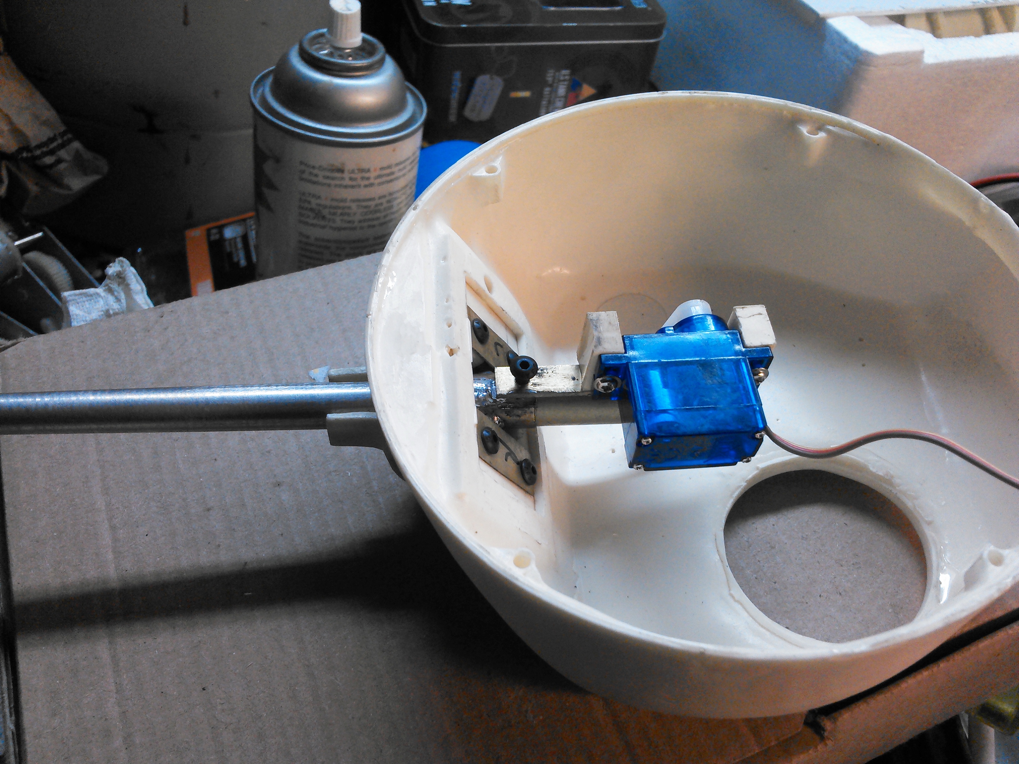
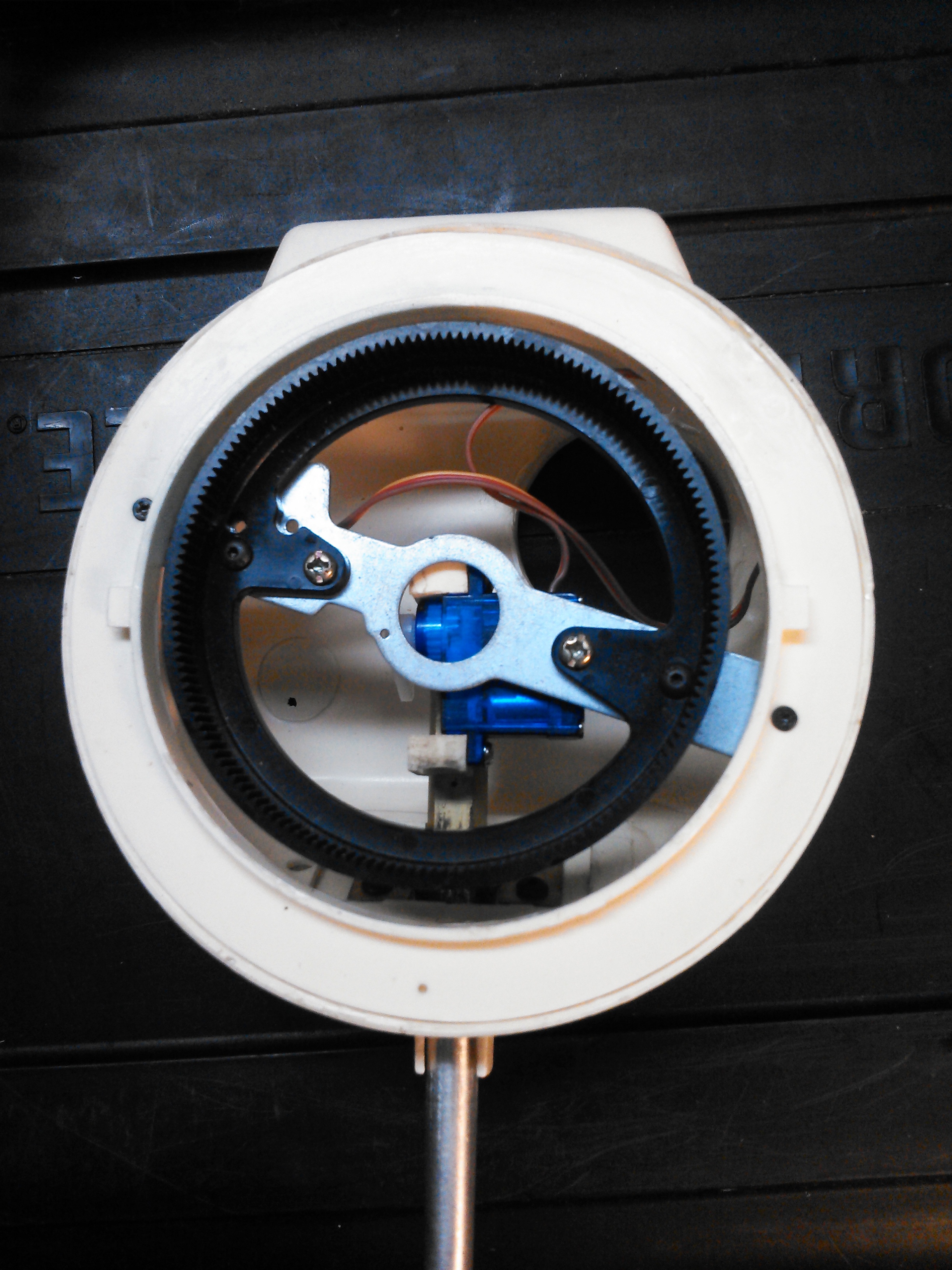
I had to lengthen the mount for the recoil servo because it was impacting the Tamiya rotation gear box when the gun was elevated and the turret came around to certain spots. This shows the new servo mount and the draglink to the barrel


Here is the whole gun mount installed in the turret. Rather than glue the rotor into the turret, I was able to screw retainer brackets to it to hold it into the turret.

https://www.youtube.com/watch?v=YUDQVaWwYpI
Here is the whole gun mount installed in the turret. Rather than glue the rotor into the turret, I was able to screw retainer brackets to it to hold it into the turret.
https://www.youtube.com/watch?v=YUDQVaWwYpI
Last edited by RichJohnson; 10-07-2016 at 07:38 PM.
10-11-2016, 06:38 AM
#12
Thread Starter
Well, Nuts!
I moved the recoil servo back just a tad too far and I found it hits the rotation box when the turret is turned 90 degrees to the right. Im going to try and move the servo forward maybe an 1/8 inch and then move it sideways maybe, and then have to rebuild a offset servo arm to stay in line with the barrel.
Im going to start pulling it apart maybe tonight and see how it goes.

 10-12-2016, 09:39 PM
#15
Thread Starter
Oh geez, finally got it rebuilt and working. What a pain in the ass that Tamiya rotation box is. Offset to one side to you have to clear it with elevation turning to the right and then clear it again when rotated around on the back end of the servo mount.
And, since I have my elevation servo in there, I had to make sure the recoil servo wouldn't hit it or I would loose depression. Finally found the sweet spot.
I took the drive gear out of the rotation box so I could do various mock ups and spin them around by hand and test up and down movement of the gun. Its all very tight, especially when the wires of the two servos, the IR, the base and the flash and an Mg all get in the damn way.
I settled on moving the servo forward about 1/8 inch and across to the other side of the bar but flush with the edge of the bar. Then I had to fabricate a big Z bar for my recoil arm on the servo. What a darn pain it all was.
Sorry, I didn't take any pics while I was working. I just powered through it one try after another.
10-20-2016, 09:01 PM
#17
Thread Starter
Made a couple more buildings for;
https://www.facebook.com/groups/SanDiegoRCTankBattles/?
Got some time to keep working. Now that the mechanical is all working i mounted a few magnets at the front of the hull to hold the hull on. Havent yet got to the rear magnets yet. Got te front glacis weld joints molded on and my commanders vane sight made up and installed.
10-21-2016, 08:15 PM
#18

Join Date: Nov 2012
Location: USA
Posts: 903
Likes: 0
Received 0 Likes
on
0 Posts
I feel your pain brother. I ran in to some similar issues on my M51. I ended up using some rubber spacers between the unit and the mounting posts to lower the rotation unit. I then mounted the turret rotation ring lower as well by making a sheet metal mount. It works, but it sounds like the motor is chewing marbles when it turns right. Left, no problem and quiet. I think the rotation unit is bad, at least one of the gears, the motor is fine...
11-26-2016, 10:01 PM
#19
Thread Starter
So I did test battle this tank last month at the San Diego battle. Our field is huge and I quickly learned that the taigen Sherman is way too slow to start out with on the field before it takes a hit. Im still tweeking my IBU power rotation settings to get it to turn better. Real shermans didn't have the super spin, just one track breaking but this tank wont turn after just one hit after it slows down. There is a big difference in performance from these 39:1 ratio gear boxes to the 69:1 mato units in the Jumbo both using the IBU2. It turns and runs fine after several hits. The taigen literally goes dead in the water. Its a combination of less gearing, weaker motors and the IBU settings so Im still playing with the learning curve on this platform set up. I plan more taigen based shermans but have to overcome the learning curve. I plan to swap to Tamiya motors to speed it up but need to buy new pinion gears. I will get around to that.
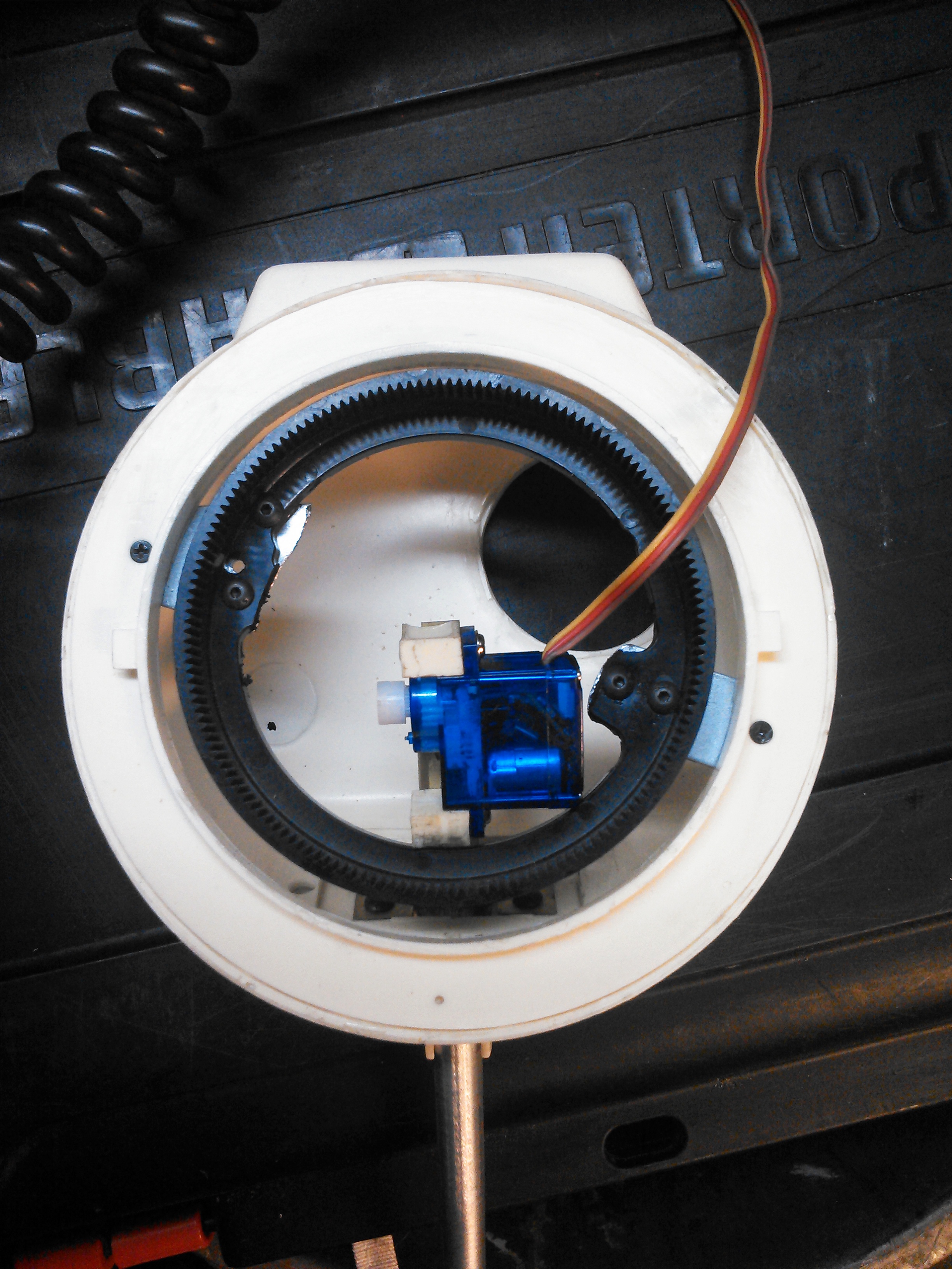
The other problem I had was my bundle of cables in the turret binding up on the recoil servo mount when the barrel elevated up and down as the turret rotated. The bundle just got in the way and would sometimes get jammed between the recoil and the turret ring.
We had a fun run battle today in San Diego and I did some more testing with this tank and this afternoon I tore it down and came up with the following.
I used the screws on the bottom of the apple base and stretched a wire between them to pull the cable bundle over to that side.

I then fabricated a ring guide to hold the bundle in one spot out of the way and installed the turret on the hull and used a model train power pack to rotate the turret around a lot to make sure there would not be any binding against the Tamiya rotation box. I think I finally have it settled now.


Now on to more body detail work and motor swap performance enhancing etc.
The other problem I had was my bundle of cables in the turret binding up on the recoil servo mount when the barrel elevated up and down as the turret rotated. The bundle just got in the way and would sometimes get jammed between the recoil and the turret ring.
We had a fun run battle today in San Diego and I did some more testing with this tank and this afternoon I tore it down and came up with the following.
I used the screws on the bottom of the apple base and stretched a wire between them to pull the cable bundle over to that side.
I then fabricated a ring guide to hold the bundle in one spot out of the way and installed the turret on the hull and used a model train power pack to rotate the turret around a lot to make sure there would not be any binding against the Tamiya rotation box. I think I finally have it settled now.
Now on to more body detail work and motor swap performance enhancing etc.
12-31-2016, 05:28 PM
#20
Thread Starter
Its hard to believe that after all the work Ive done on this model so far Im still on one page of posts LOL.
Any way, Today I modified the taigen 3.1 trannys.
They are stock ratio of 39:1 with a brass 10 tooth pinion gear. scale speed was about 18mph, just felt slow.
I removed the stock motors and installed Tamiya Johnson motors and new steel 11 tooth pinions.
This took some fitting and filing of the mount holes for a good gear mesh.
The new gear ratio raised to 33:1 which is getting kinda high and weak on torque but the scale speed jumped to like 30 pmh. Holy crap.
The Tamiya Johnson motors are so good they speed the tank up quite a bit then decrease the gear ratio one tooth on top of it and wow.
A stock Tamiya Sherman is 59:1 ratio and scale speed of 23.
Im now pondering the opposite. What if I put an 8 tooth pinion gear on the taigen with the Tamiya motors. Remember the stock is 10, I went up to 11.
Im betting the resulting gear ratio would be somewhere in the neighborhood of 51:1 so that would theoretically put me around 25mph ish.
Just some thoughts. I think Im going to be doing more experimenting.
Any way, this tank is coming along nicely and wow its fast. Probably going to have to reduce that...
12-31-2016, 09:34 PM
#22
Thread Starter
Hey that's great man. That's why I bother to post all these things of trial and error so people can get ideas on how to make stuff or to solve the problems I worked out.
02-06-2017, 09:49 PM
#23
Thread Starter
Well I finally got some time to do some model work. Got my footman loops mounted on the back of the turret and got some paint on the turret and chassis and differential cover.
I swapped in the newer taigen wheels that have the stamped spokes because they are appropriate for an ALCO tank. They were raw metal so I primed and painted them then baked the paint in the over at 350 for about an hour.
Now just to get to work making my lift rings brush guards and the like of detail compliment on the hull and it will be done.
02-07-2017, 08:16 AM
#24
I feel your pain brother. I ran in to some similar issues on my M51. I ended up using some rubber spacers between the unit and the mounting posts to lower the rotation unit. I then mounted the turret rotation ring lower as well by making a sheet metal mount. It works, but it sounds like the motor is chewing marbles when it turns right. Left, no problem and quiet. I think the rotation unit is bad, at least one of the gears, the motor is fine...
