


Getting closer to an Open Source tank transmission
 07-20-2017, 10:10 AM
#1
I have sourced the motors and the gears. There is a little machining to do in that a spacer must be drilled out slightly to extend the stock shaft that comes with plastic geared transmission.
The transmission frame will be 3D printed.

Steve
The transmission frame will be 3D printed.
Steve

 07-24-2017, 05:40 PM
#4

Join Date: Dec 2014
Posts: 192
Likes: 0
Received 0 Likes
on
0 Posts
Looking good. Cant wait to see how this turns out.
If the speed is roughly correct, enough torque, and the axles only turn under power... it will be great. With a printable frame and some easy to source parts it will be an excellent alternative to off-the-shelf gearboxes.
If the speed is roughly correct, enough torque, and the axles only turn under power... it will be great. With a printable frame and some easy to source parts it will be an excellent alternative to off-the-shelf gearboxes.
07-25-2017, 04:00 PM
#5
Man I totally screwed the pooch on the placement of the motor - used the drawings provided on Amazon - not sure if the drawings are wrong or I screwed up. But the motor is larger than the dimensions said. Anyway I cut away some plastic - lost 2 mount point screws but hopefully 4 will be enough. If not I may have to make an adapter plate or something. Also my motor mount holes did not line up. Have to print another one tomorrow.
I was able to salvage the original shaft from the plastic HL transmission - bought some 6mm spacers from McMaster-Carr and drilled them out to press onto the knurled HL shaft. The gearing works.

Steve
I was able to salvage the original shaft from the plastic HL transmission - bought some 6mm spacers from McMaster-Carr and drilled them out to press onto the knurled HL shaft. The gearing works.
Steve
07-25-2017, 05:15 PM
#6
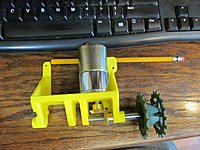
Nice work Steve. I'm guessing it's perspective but to me the output shaft looks out of alignment. Imagine a line down the center of the motor and a line through the center line of the sprocket. Don't look parallel to me, like I said could be image perspective though.
08-08-2017, 07:33 PM
#9
Here is an update.
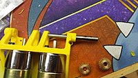
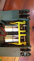
I revised the design to lighten the frame and use less plastic, making it faster and cheaper to print.
Also, I angled the motors slightly so that they do not interfere with some of the old mounting and alignment holes for the original transmissions. This way you do not have to modify your tank at all to use this transmission.
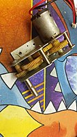
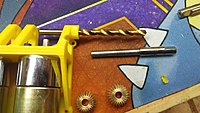
I am able to salvage the main shafts from the original Heng Long transmission to save on cost and ease manufacturing.
First, we remove the main shaft from the original Heng Long transmission:

Then we need to remove the gear pressed onto it. We can start moving it by using a pair of pliers to bear against the side of the gear, and tap it off the spline. Then we can finish driving the shaft out using a small punch.

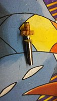


Next I found some 6mm OD x 45mm spacers, which can be used to lengthen the stock Heng Long shaft. But to make it fit we have to drill it out. I believe I used a #9 drill bit. You want to drill it out just slightly smaller than the knurling on the original shaft.


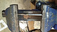
After it is drilled out, we can use a bench vice to easily press the shaft over the spline on the original shaft. This completes the shaft.


The holes in the 3D printed part are deliberately undersized, so next I drill them out to accept the shafts with a perfect fit. It's likely that with this plastic no bearings will be necessary. If they turn out to be necessary, it will be trivial to add them simply by drilling the holes a bit larger.
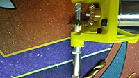
Because when you press the spacer over the knurling on the original shaft it may slightly bulge it larger than the 6mm OD it originally had, you may need to very slightly drill out one of the bevel gears so that it easily fits over the shaft.

To set the spacing of the gears, first slip a bevel gear onto the motor shaft, and then temporarily install the main shaft and its bevel gear. Push the bevel gear on the motor shaft as far forward as needed to fully engage the main shaft bevel gear, and tighten its set screw onto the motor shaft.
Then remove the main shaft and its bevel gear - you can't install the transmission in the tank with the main shafts in place.

I'm using white lithium grease to lubricate the shaft. I hope this will be safe with this plastic.

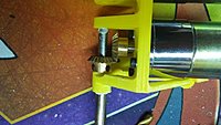
Finally, we install the transmission in the tank, and re-install the main shafts and their bevel gears.

I also salvaged the original wiring pigtail off of the Heng Long motors, as well as the capacitors or whatever they are that evidently tie the leads to the motor frame. I guess this eliminates noise or something.
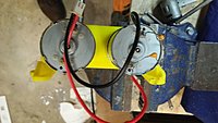

I've only got one motor wired up right now, but it runs. The speed seems good - slower than stock but stock was too fast anyway. The motor is supposedly 200 RPM out at 12V. I'm guessing this is a bit slower at tank voltage. Torque seems a bit light though when I grab the drive sprocket. I may have to investigate a more torqey motor. But I won't know for sure until I get the tank all together and test drive it.
But it seems likely to work. The motors are roughly $12 each, and you need 2 of them.. The shafts are McMaster-Carr: Stainless Steel Unthreaded Spacer - 6 mm OD, 45 mm Length, for M4 Screw Size - 92871A208, and are roughly $3 each, and you need 2 of them. The bevel gears are from Servo City https://www.servocity.com/6mm-bevel-gears and are about $6 each, and you need 4 of them. I don't know how much the frame will cost to print at Shapeways, but let's just guess $30 for now.
So, you will be able to build this transmission for under $100.
This is for my Heng Long Jagdpanther. After I get it working, I'll move on to my HL Sherman.
Steve
I revised the design to lighten the frame and use less plastic, making it faster and cheaper to print.
Also, I angled the motors slightly so that they do not interfere with some of the old mounting and alignment holes for the original transmissions. This way you do not have to modify your tank at all to use this transmission.
I am able to salvage the main shafts from the original Heng Long transmission to save on cost and ease manufacturing.
First, we remove the main shaft from the original Heng Long transmission:
Then we need to remove the gear pressed onto it. We can start moving it by using a pair of pliers to bear against the side of the gear, and tap it off the spline. Then we can finish driving the shaft out using a small punch.
Next I found some 6mm OD x 45mm spacers, which can be used to lengthen the stock Heng Long shaft. But to make it fit we have to drill it out. I believe I used a #9 drill bit. You want to drill it out just slightly smaller than the knurling on the original shaft.
After it is drilled out, we can use a bench vice to easily press the shaft over the spline on the original shaft. This completes the shaft.
The holes in the 3D printed part are deliberately undersized, so next I drill them out to accept the shafts with a perfect fit. It's likely that with this plastic no bearings will be necessary. If they turn out to be necessary, it will be trivial to add them simply by drilling the holes a bit larger.
Because when you press the spacer over the knurling on the original shaft it may slightly bulge it larger than the 6mm OD it originally had, you may need to very slightly drill out one of the bevel gears so that it easily fits over the shaft.
To set the spacing of the gears, first slip a bevel gear onto the motor shaft, and then temporarily install the main shaft and its bevel gear. Push the bevel gear on the motor shaft as far forward as needed to fully engage the main shaft bevel gear, and tighten its set screw onto the motor shaft.
Then remove the main shaft and its bevel gear - you can't install the transmission in the tank with the main shafts in place.
I'm using white lithium grease to lubricate the shaft. I hope this will be safe with this plastic.
Finally, we install the transmission in the tank, and re-install the main shafts and their bevel gears.
I also salvaged the original wiring pigtail off of the Heng Long motors, as well as the capacitors or whatever they are that evidently tie the leads to the motor frame. I guess this eliminates noise or something.
I've only got one motor wired up right now, but it runs. The speed seems good - slower than stock but stock was too fast anyway. The motor is supposedly 200 RPM out at 12V. I'm guessing this is a bit slower at tank voltage. Torque seems a bit light though when I grab the drive sprocket. I may have to investigate a more torqey motor. But I won't know for sure until I get the tank all together and test drive it.
But it seems likely to work. The motors are roughly $12 each, and you need 2 of them.. The shafts are McMaster-Carr: Stainless Steel Unthreaded Spacer - 6 mm OD, 45 mm Length, for M4 Screw Size - 92871A208, and are roughly $3 each, and you need 2 of them. The bevel gears are from Servo City https://www.servocity.com/6mm-bevel-gears and are about $6 each, and you need 4 of them. I don't know how much the frame will cost to print at Shapeways, but let's just guess $30 for now.
So, you will be able to build this transmission for under $100.
This is for my Heng Long Jagdpanther. After I get it working, I'll move on to my HL Sherman.
Steve
08-09-2017, 03:40 AM
#10
I was a little dubious about the need for this when you started, however I have to applaud all the effort your put in. The result looks excellent! I will definitely have to try some of these out at some point. It's also another strand to what we as tankers can assemble and customise out selves, which can't be a bad thing!!
08-09-2017, 04:28 AM
#11

Join Date: Mar 2017
Posts: 186
Likes: 0
Received 0 Likes
on
0 Posts
Steve,
I am very much impressed with your work. I would like to ask if when testing the performance of your test drive, please disclose whether your test tank has metal tracks and wheels as well?
Now, if only a stack-able planetary gearbox on each motor......then you could dial-in the performance an individual tank has........
Springman
08-09-2017, 06:20 AM
#12
I have one jagdpanther with plastic wheels and tracks, and one with metal, so I will try both!
Also, this is the motor I am currently using:
https://www.amazon.com/gp/product/B0...?ie=UTF8&psc=1
Steve
Also, this is the motor I am currently using:
https://www.amazon.com/gp/product/B0...?ie=UTF8&psc=1
Steve
08-09-2017, 06:33 AM
#13
Join Date: Mar 2017
Posts: 186
Likes: 0
Received 0 Likes
on
0 Posts
Originally Posted by ...this is the motor I am currently using: [url=https://www.amazon.com/gp/product/B01KTYONKO/ref=oh_aui_detailpage_o00_s00?ie=UTF8&psc=1
https://www.amazon.com/gp/product/B01KTYONKO/ref=oh_aui_detailpage_o00_s00?ie=UTF8&psc=1[/url]
Steve
Steve
The motor you show seems to have a "fixed" planetary gearbox. I do not know if it can be modified easily. But, a "stack-able" planetary gearbox is.....
You have maded a GREAT first step, I was just wondering if it can be augmented.
Thanks again!
Springman
08-09-2017, 06:54 AM
#15
Join Date: Mar 2017
Posts: 186
Likes: 0
Received 0 Likes
on
0 Posts
Well, here is a good example of one you might like to play with to understand them: TowerHobbies.com Tamiya Planetary Gearbox Set
I am not sure it would be good for this application; but, it is good as a learning tool.
Springman
I am not sure it would be good for this application; but, it is good as a learning tool.
Springman
08-09-2017, 07:39 AM
#17
Join Date: Mar 2017
Posts: 186
Likes: 0
Received 0 Likes
on
0 Posts
These motors are considerably more expensive, but appear to have over 10 times the torque:
https://www.servocity.com/313-rpm-hd...ary-gear-motor
Steve
https://www.servocity.com/313-rpm-hd...ary-gear-motor
Steve
Springman
08-10-2017, 05:10 PM
#18
Could also look at gearhead/planetary combo's instead of a plain brushed motor to gain advantage. Would increase depth needed for motor into hull though. May also bring up issues with mounting as most output shafts from the planetary are offset.
https://www.servocity.com/motors-act...ty-gear-motors
https://www.servocity.com/motors-act...ty-gear-motors
Last edited by TheBennyB; 08-10-2017 at 05:12 PM.
08-10-2017, 06:34 PM
#19
Hi Benny,
That link goes to a jump point for many motors. Which one in particular are you recommending?
The motor I am currently using is a planetary gear/motor combo. See pictures above.
Steve
That link goes to a jump point for many motors. Which one in particular are you recommending?
The motor I am currently using is a planetary gear/motor combo. See pictures above.
Steve
08-11-2017, 02:57 AM
#20
Join Date: Mar 2017
Posts: 186
Likes: 0
Received 0 Likes
on
0 Posts
I think the "Premium Planetary Gear Motors" - Link: https://www.servocity.com/motors-actuators/gear-motors/standard-duty-gear-motors/premium-planetary-gear-motors
is the most likely to be used as it has the widest RPM range (26 to 2737 rpms) - the motors appear to be about $28.00 each. If they all support the same motor-mounting, that would provide an excellent range of selection. Also, the planetary gearing should provide for smooth operations and good torque. I for one think that this is an excellent alternative to the standard RC Tank gearbox/motor setups available as they are most likely to have greater service life and torque - and possibly quieter operational noise levels.
Springman
08-11-2017, 04:44 AM
#21
The motor I am currently using is 200 RPM and has 2.2 kgf/cm.
This motor is 280 RPM and has 5 kgf/cm:
https://www.servocity.com/280-rpm-pr...ary-gear-motor
This one is 350 RPM and has 5.7 kgf/cm:
https://www.servocity.com/350-rpm-pr...ary-gear-motor
But the servocity motors also say, " Gear train damage can occur if stalled (locked)." So if you stall out your tank by trying to go up too steep a grade or something you could damage the transmission. Probably true with any of these.
So, the servocity motors appear to offer over twice the torque of the uxcell motors I currently have. A redesign may be in order!
Steve
08-11-2017, 05:05 AM
#22
Join Date: Mar 2017
Posts: 186
Likes: 0
Received 0 Likes
on
0 Posts
The motor I am currently using is 200 RPM and has 2.2 kgf/cm.
This motor is 280 RPM and has 5 kgf/cm:
https://www.servocity.com/280-rpm-pr...ary-gear-motor
This one is 350 RPM and has 5.7 kgf/cm:
https://www.servocity.com/350-rpm-pr...ary-gear-motor
But the servocity motors also say, " Gear train damage can occur if stalled (locked)." So if you stall out your tank by trying to go up too steep a grade or something you could damage the transmission. Probably true with any of these.
So, the servocity motors appear to offer over twice the torque of the uxcell motors I currently have. A redesign may be in order!
Steve
This motor is 280 RPM and has 5 kgf/cm:
https://www.servocity.com/280-rpm-pr...ary-gear-motor
This one is 350 RPM and has 5.7 kgf/cm:
https://www.servocity.com/350-rpm-pr...ary-gear-motor
But the servocity motors also say, " Gear train damage can occur if stalled (locked)." So if you stall out your tank by trying to go up too steep a grade or something you could damage the transmission. Probably true with any of these.
So, the servocity motors appear to offer over twice the torque of the uxcell motors I currently have. A redesign may be in order!
Steve
I don't see climbing as a problem, even a 2kg/cm a 1/16th tank will have tremendous torque....
What would be a problem would be purposely jamming or locking the drive sprockets.......
Springman
08-11-2017, 05:15 AM
#23
Join Date: Mar 2017
Posts: 186
Likes: 0
Received 0 Likes
on
0 Posts
Steve,
I would also consider making a 3D printed motor mounting chassis with a full bottom plane with no chassis/lower hull mounting holes that would allow a buyer to make his own....a "GENERIC" that lets the buyer drill the holes and add bottom spacers for proper mounting...... Its a thought.....
If you can supply the outer diameter of the drive sprockets (assuming the right had drive or bevel gears are 1:1, a scale speed could be determined......
Springman
08-11-2017, 05:35 AM
#24
Well, 1kgf/cm is about 67ft/lbs.....
Torque Conversion - FREE Unit Converter
I'm getting 1 kgf/cm is about .07 ft-lbs.
67 ft-lbs is about the torque needed to install an AR15 barrel - I could turn a garden tractor wheel with that!
If you can supply the outer diameter of the drive sprockets (assuming the right had drive or bevel gears are 1:1, a scale speed could be determined......
Steve
08-11-2017, 05:39 AM
#25
Join Date: Mar 2017
Posts: 186
Likes: 0
Received 0 Likes
on
0 Posts
Are you sure?
Torque Conversion - FREE Unit Converter
I'm getting 1 kgf/cm is about .07 ft-lbs.
67 ft-lbs is about the torque needed to install an AR15 barrel - I could turn a garden tractor wheel with that!
I'd have to get home and measure them. They are stock HL Jagdpanther drive sprockets.
Steve
Torque Conversion - FREE Unit Converter
I'm getting 1 kgf/cm is about .07 ft-lbs.
67 ft-lbs is about the torque needed to install an AR15 barrel - I could turn a garden tractor wheel with that!
I'd have to get home and measure them. They are stock HL Jagdpanther drive sprockets.
Steve