


1/5 scale K2 black panther tank
 09-14-2023, 01:58 AM
#126

Thread Starter

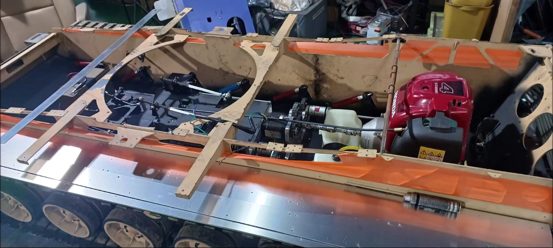
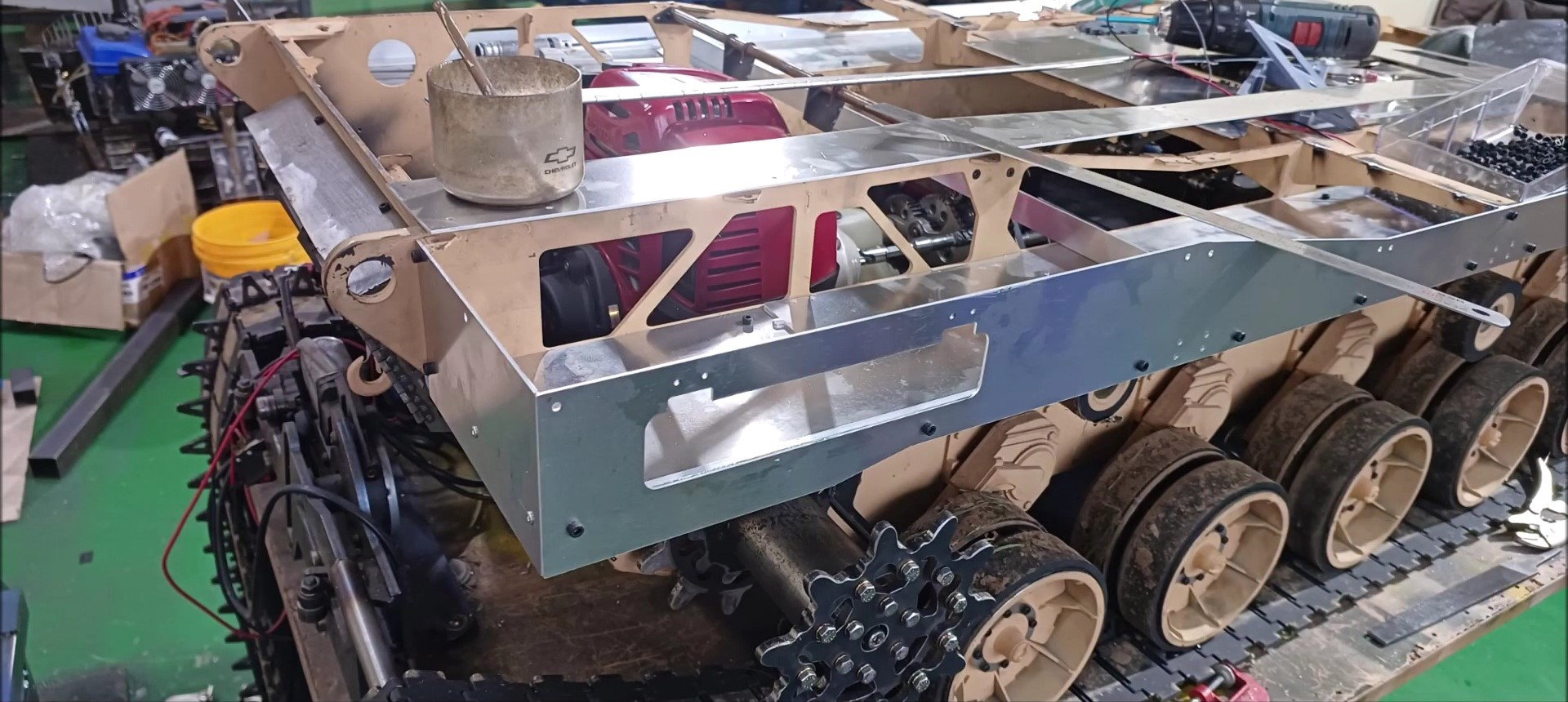
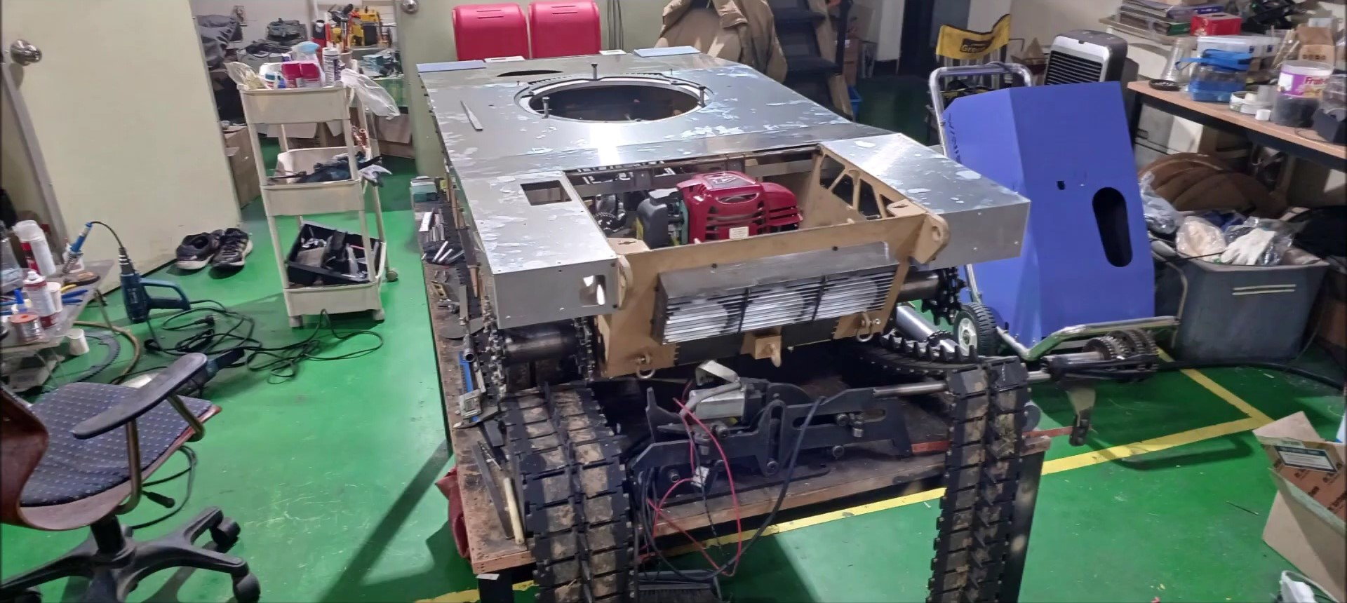
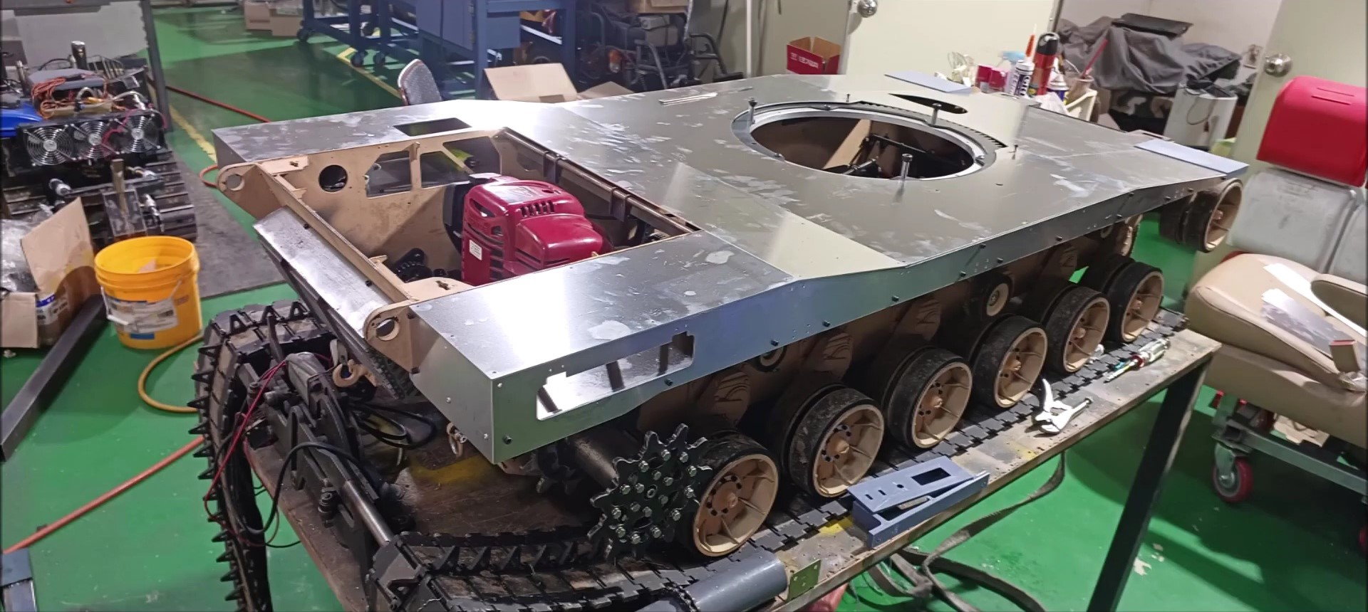
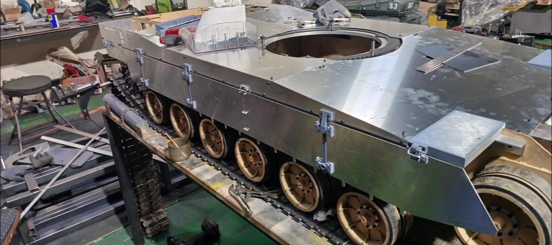
Today, we conducted an outdoor test of the K2 tank. Prior to going outdoors, the upper plate of the tank was installed to minimize the flow of dust from driving into the tank.
The attached photos show temporary work before going outside.
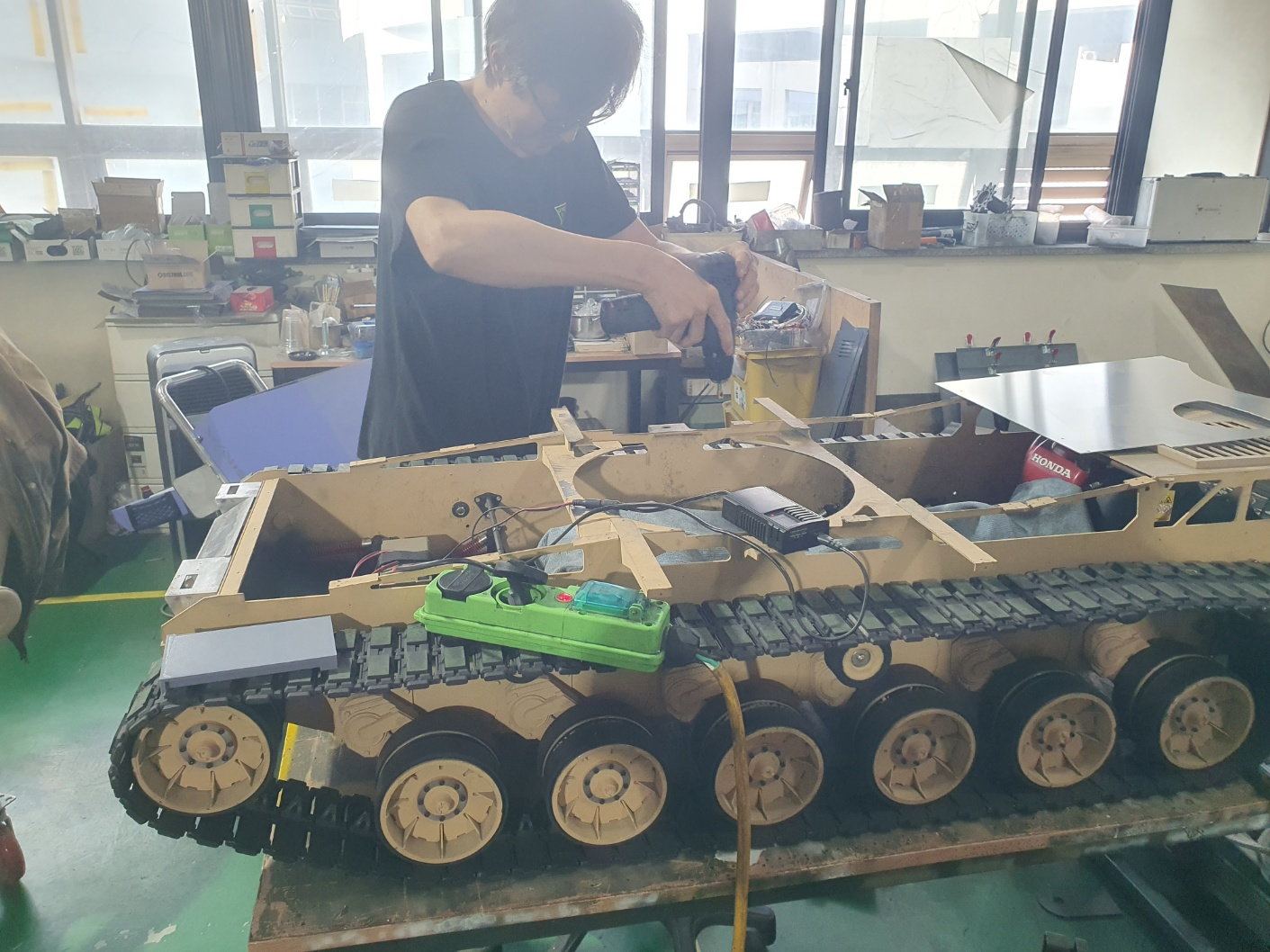
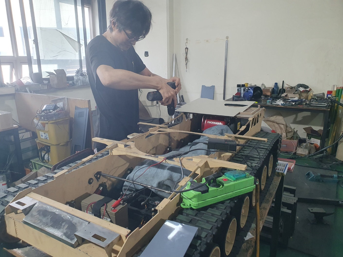
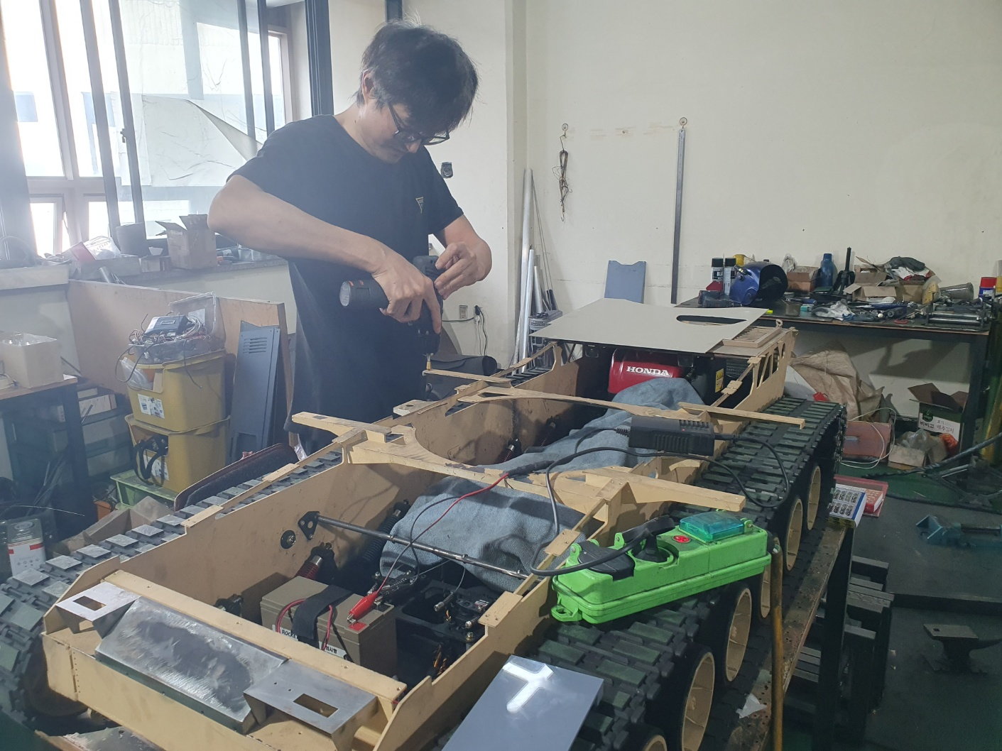
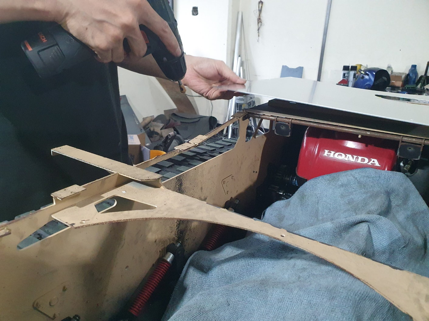
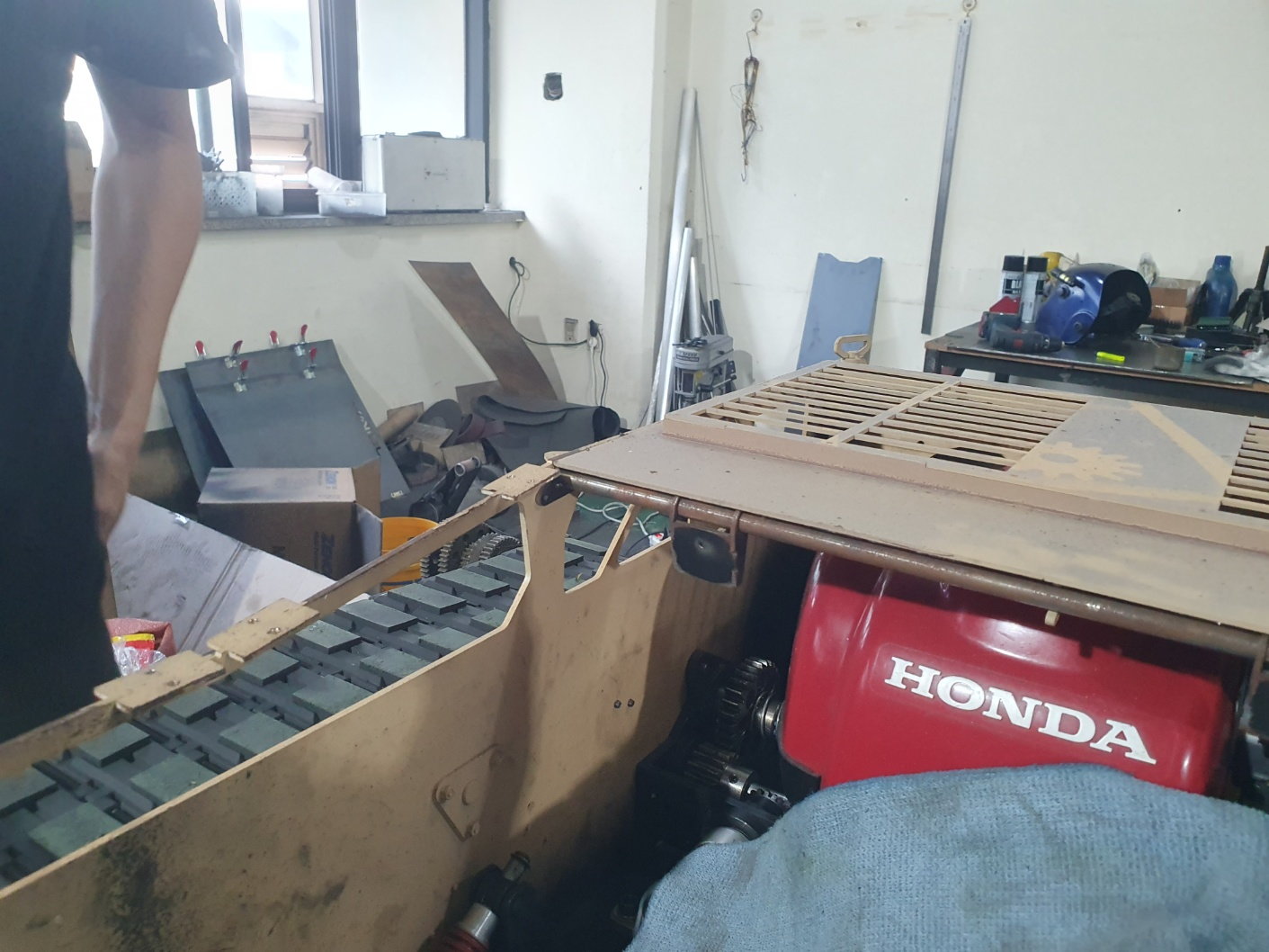
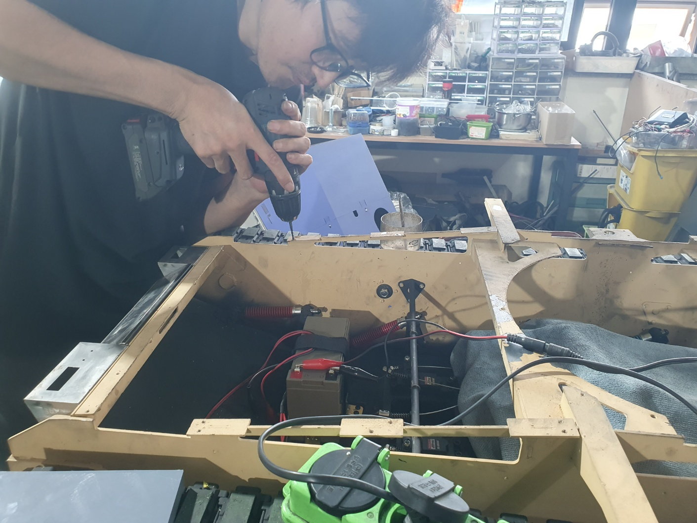
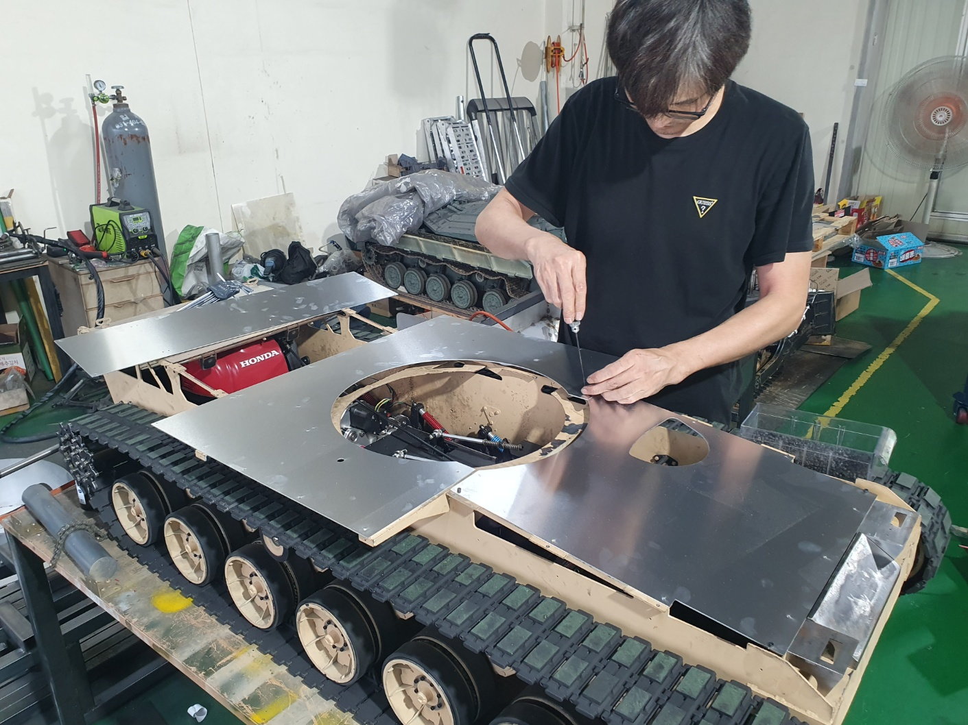
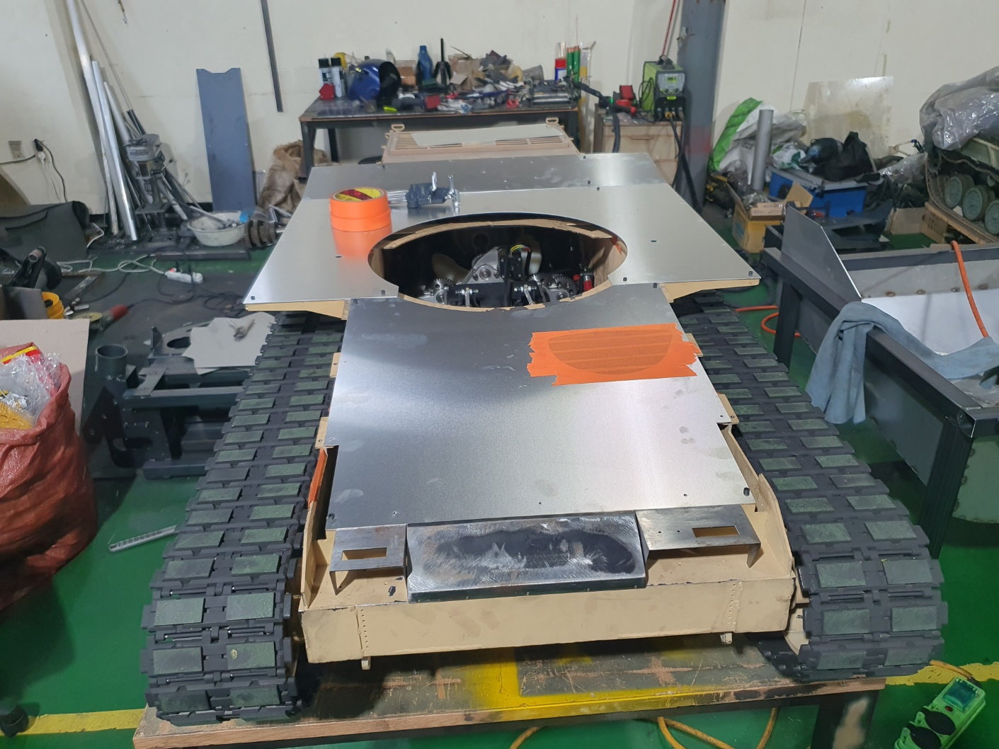
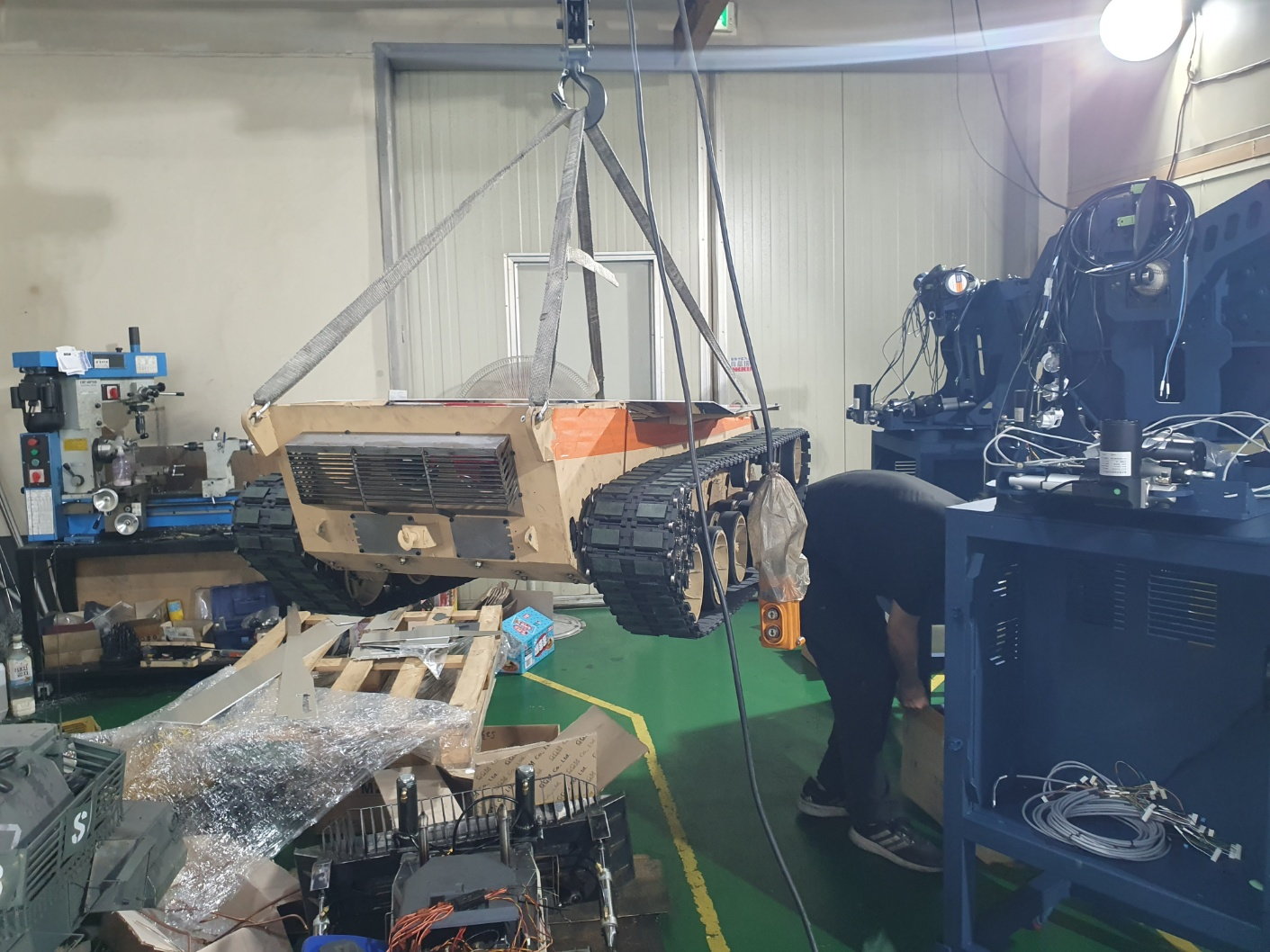
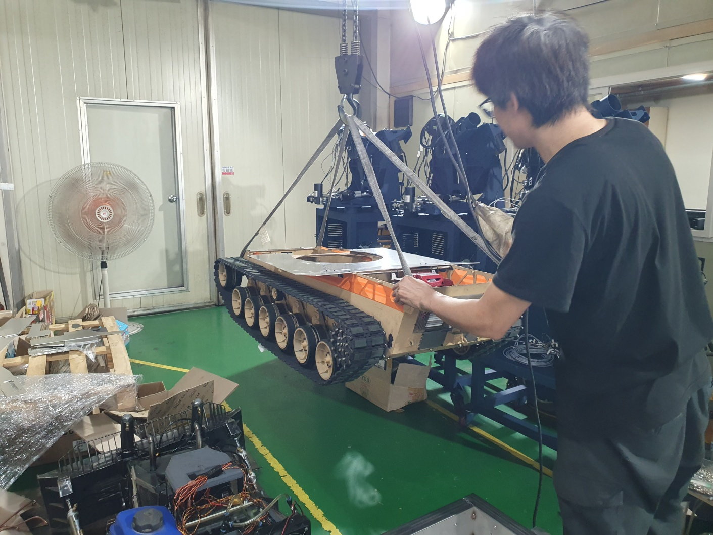
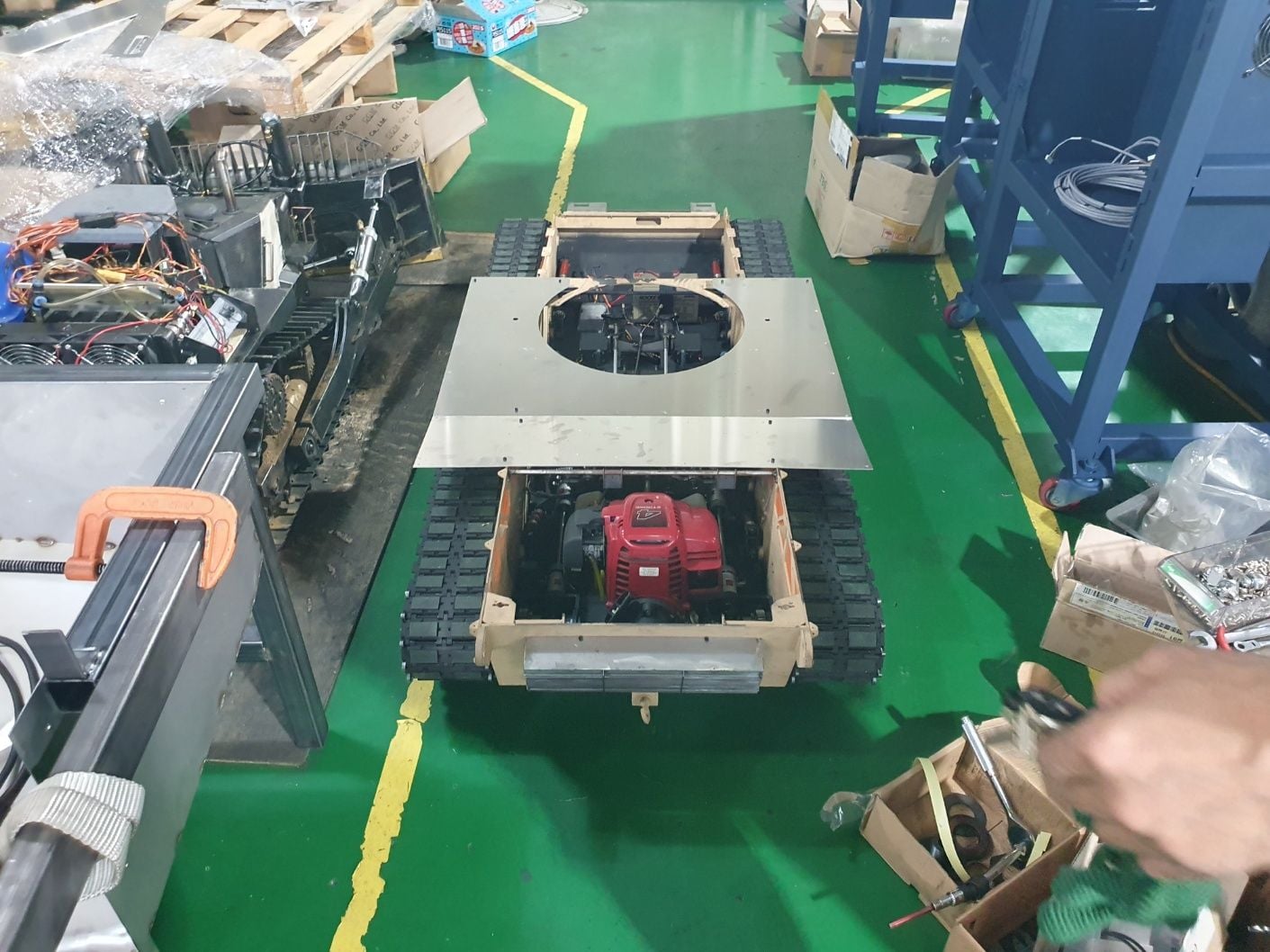
The attached photos show temporary work before going outside.
 09-14-2023, 02:01 AM
#127
Thread Starter
I share a short video of a tank going up a slope of about 40 degrees with a large gear ratio.
Last edited by PE YOUNG; 09-14-2023 at 02:27 AM.
09-22-2023, 04:57 AM
#129
Thread Starter
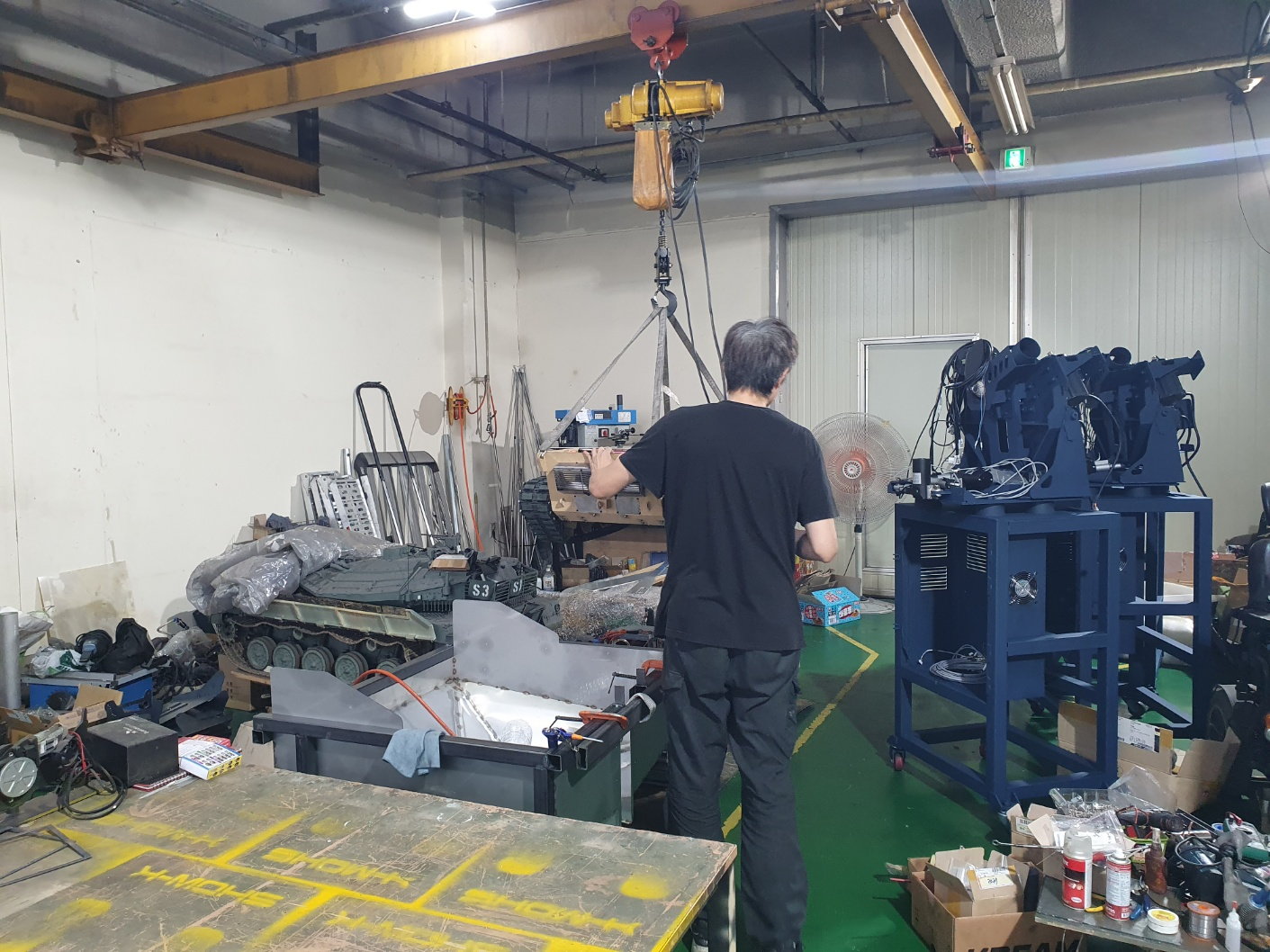
The K2 tank is currently manufacturing the exterior shape of the body, and after completion, the warehouse for operation and storage measured the weight of the 1/6 scale chieftain tank that was made in the past to check the performance of the newly purchased scale.
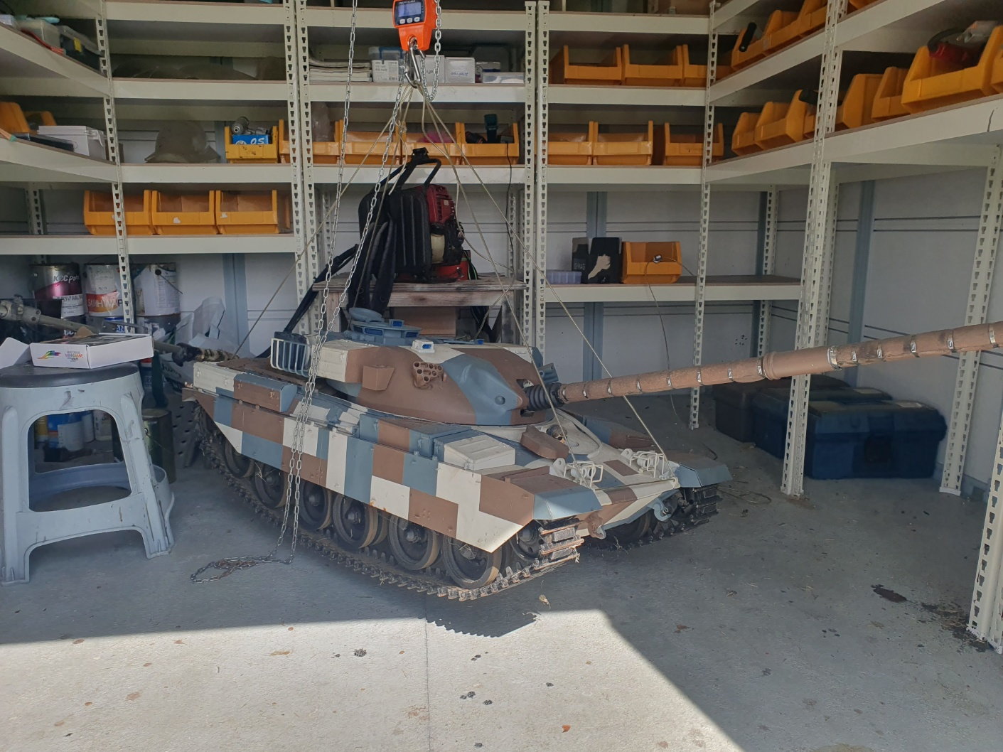
In order to check the performance of the newly purchased scale, we measured the weight of the 1/6 scale chieftain tank we made in the past.
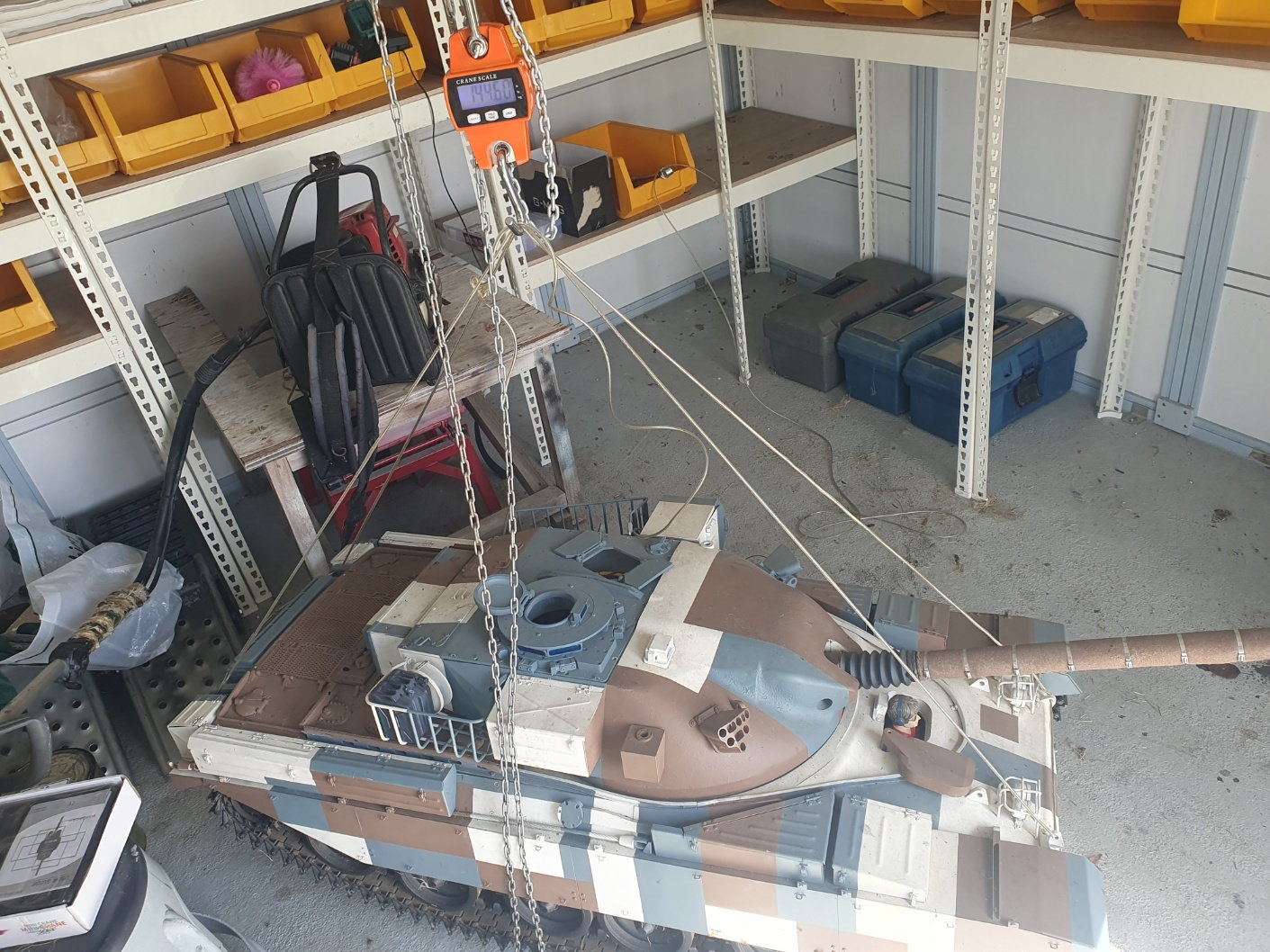
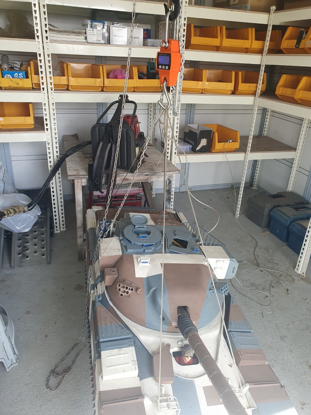
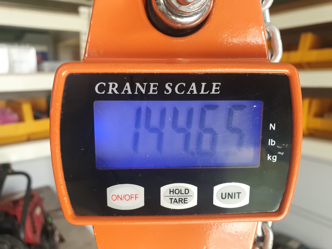
The 1/6 scale chieftain tank weighed 144.65kg.
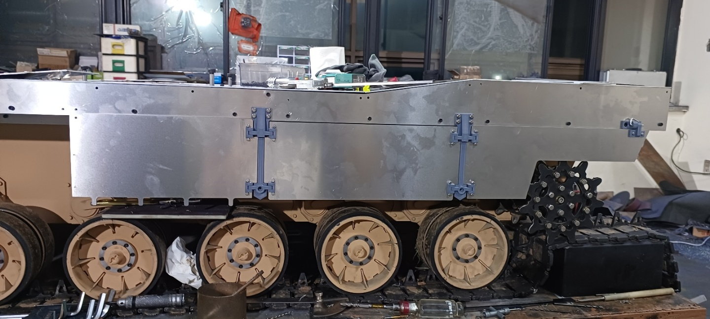
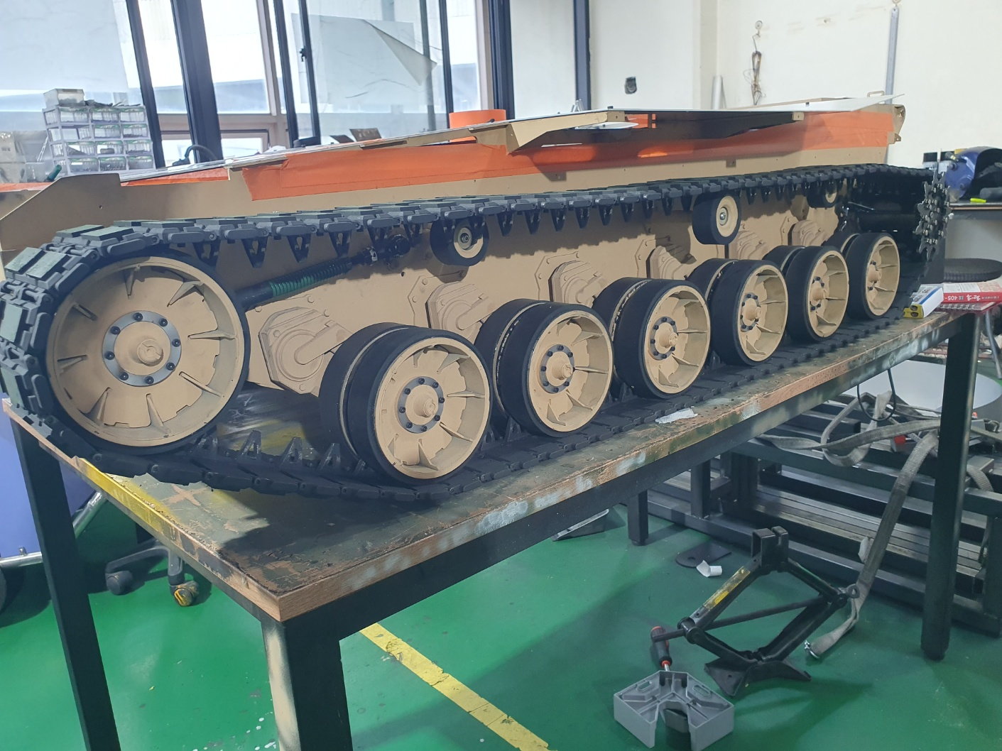
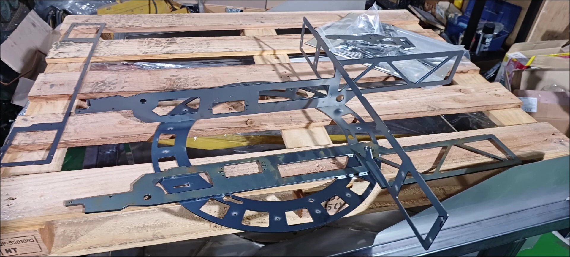
The K2 tank is currently producing upper hull work and side skirts that make up the exterior features of the body.

The steel parts that will make up the turret of the k2 tank have been outsourced and arrived.
In order to check the performance of the newly purchased scale, we measured the weight of the 1/6 scale chieftain tank we made in the past.
The 1/6 scale chieftain tank weighed 144.65kg.
The K2 tank is currently producing upper hull work and side skirts that make up the exterior features of the body.
The steel parts that will make up the turret of the k2 tank have been outsourced and arrived.
The following users liked this post:
Hackworth (09-22-2023)
09-22-2023, 01:19 PM
#130
Thread Starter
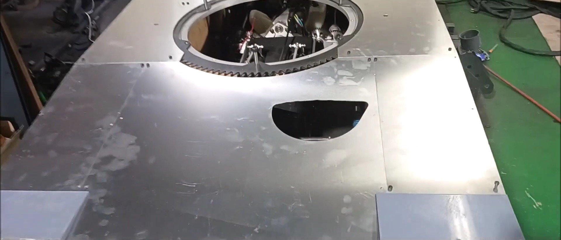
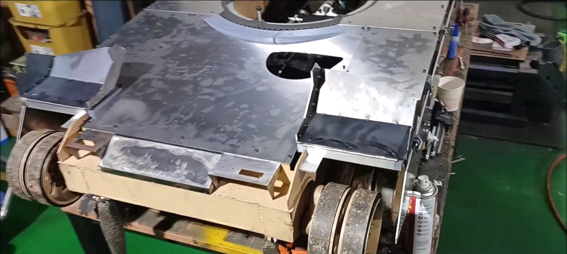
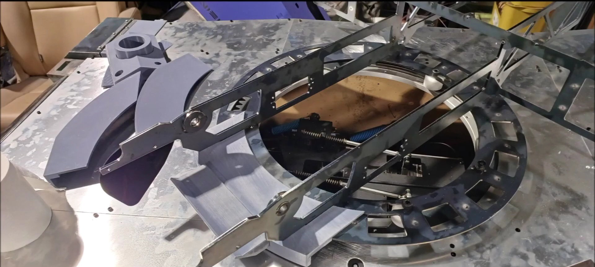
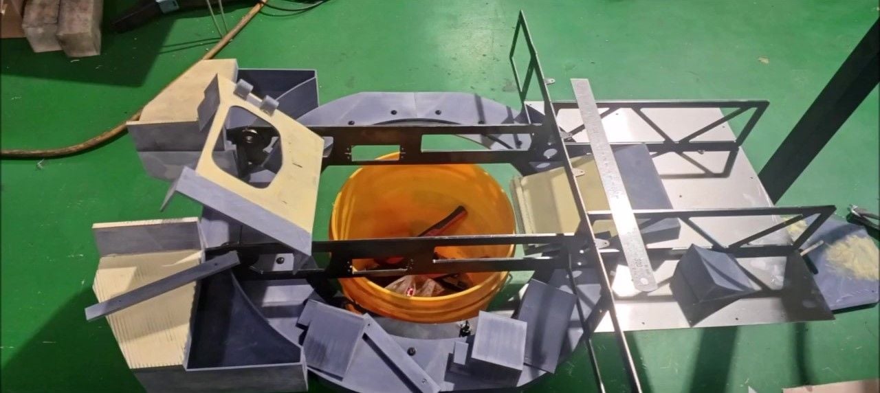
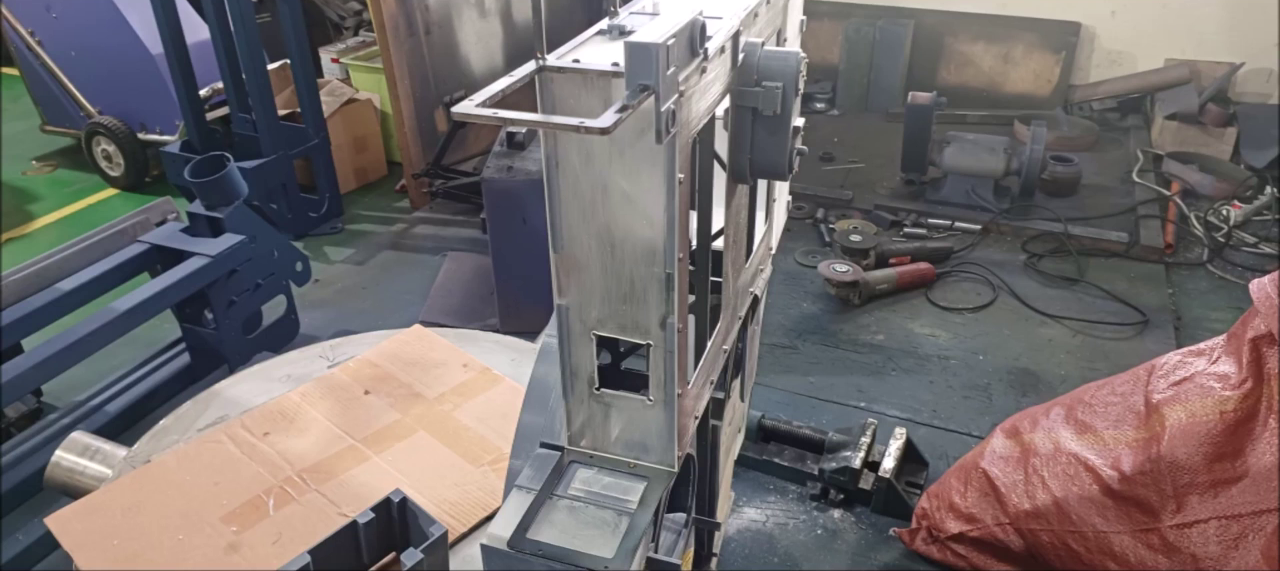
As I introduced earlier, we carried out the external work of the K2 tank's body this week. A variable turret ring was installed and tested.
The following users liked this post:
tankme (09-22-2023)
09-23-2023, 06:14 PM
#131
Thread Starter
I'll post the pictures about episode 28 and explain it.
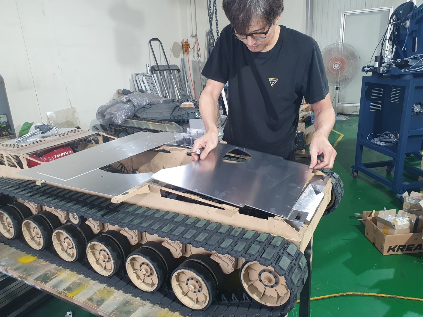
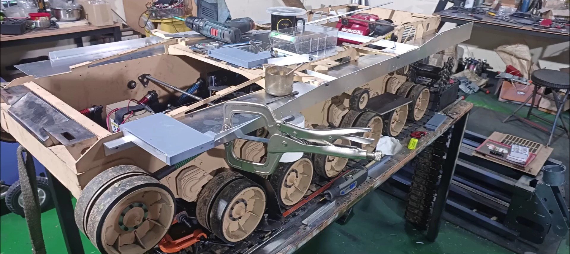
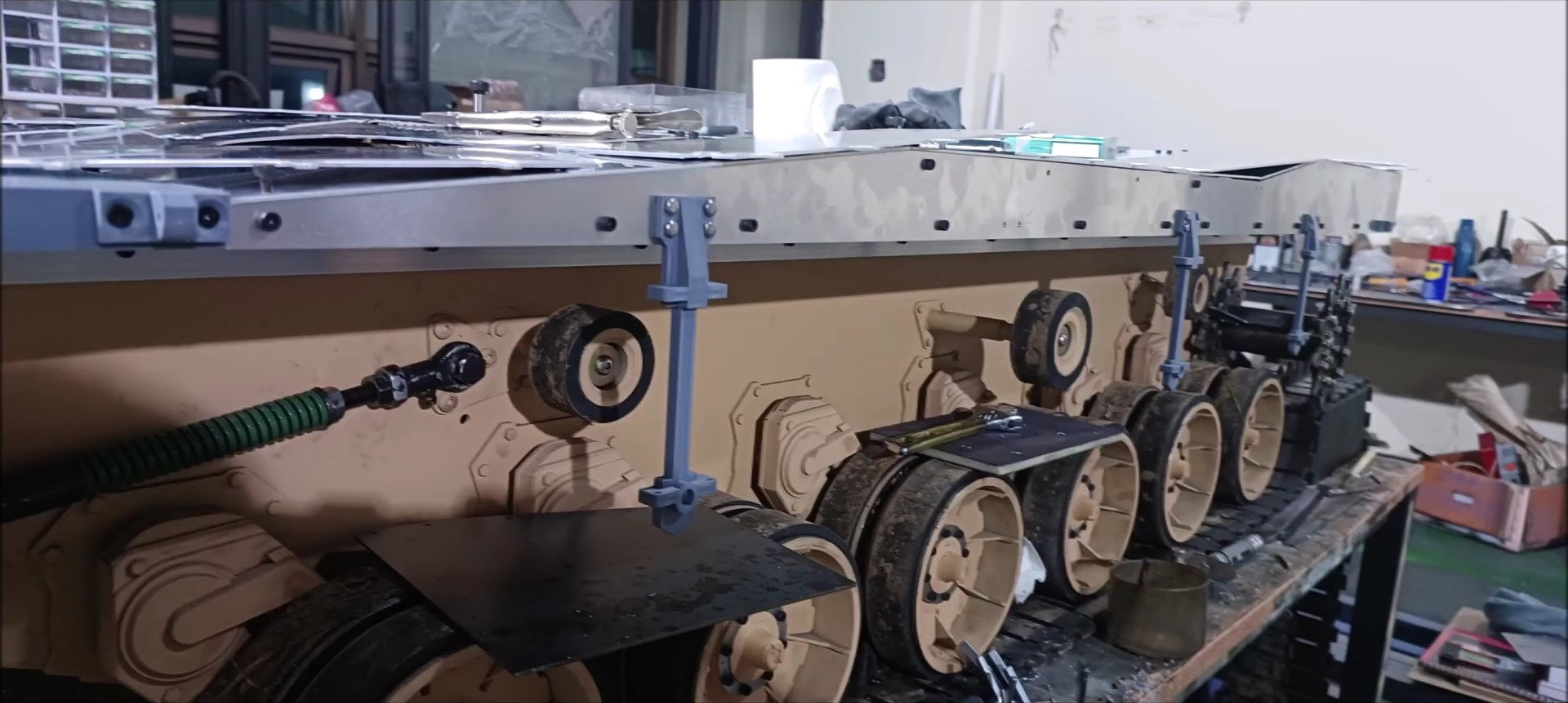
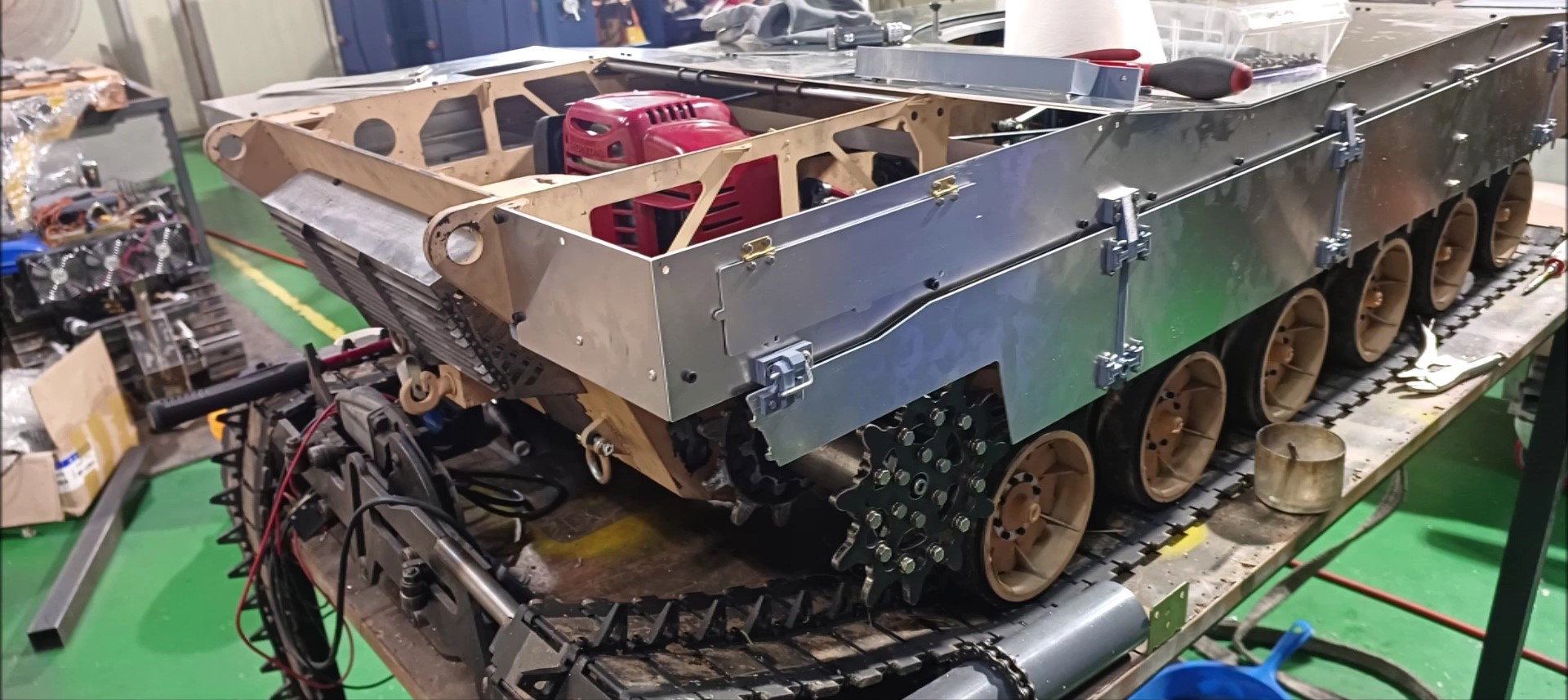
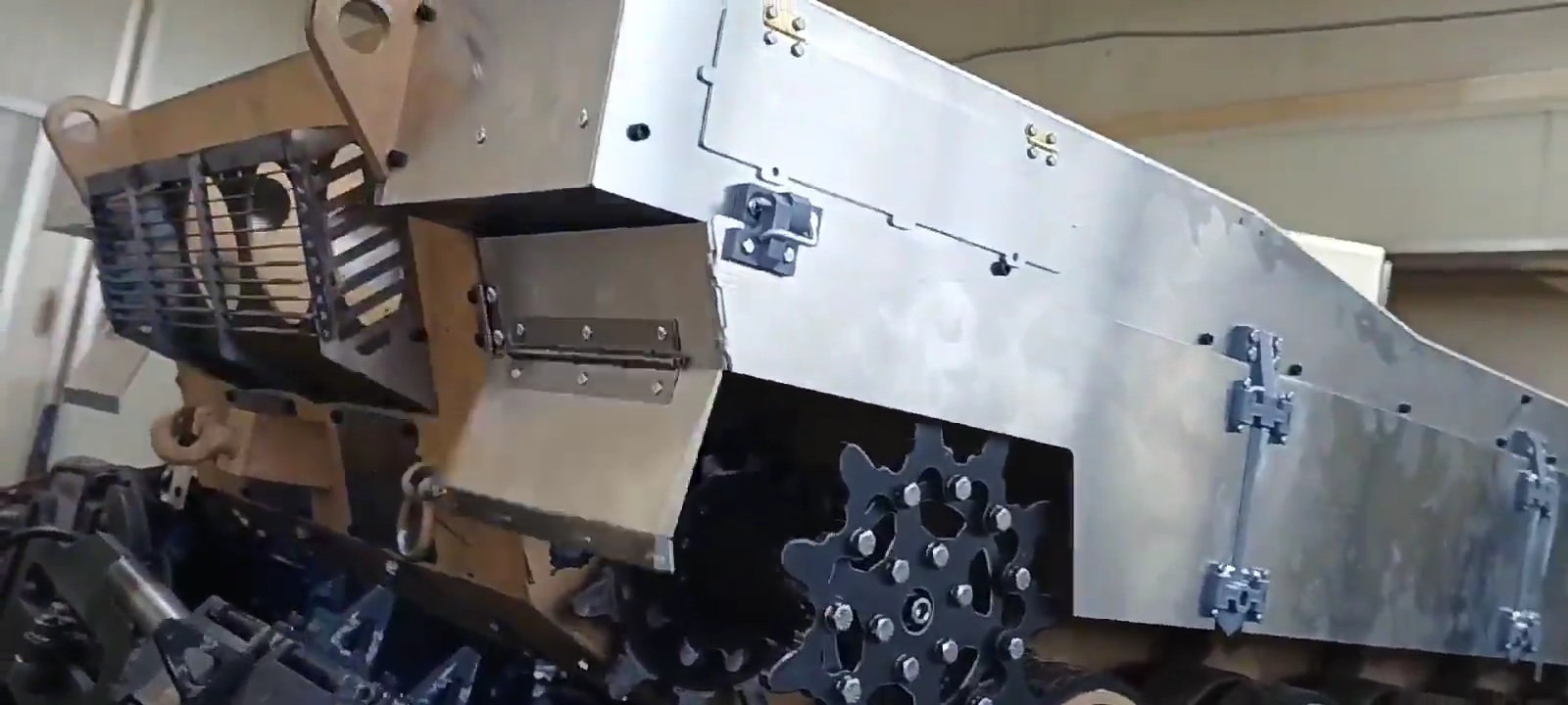
After the last outdoor test, we prepared the work of making the appearance of the tank.
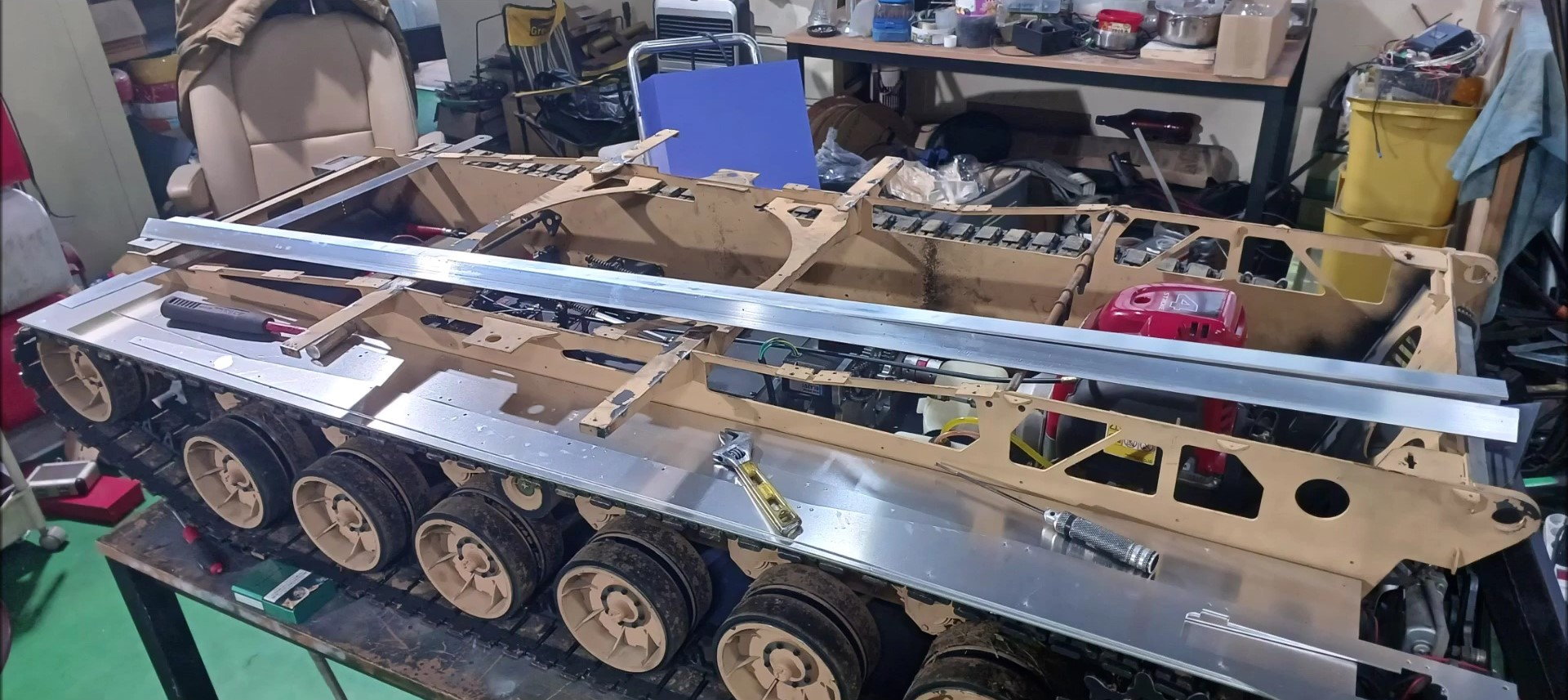
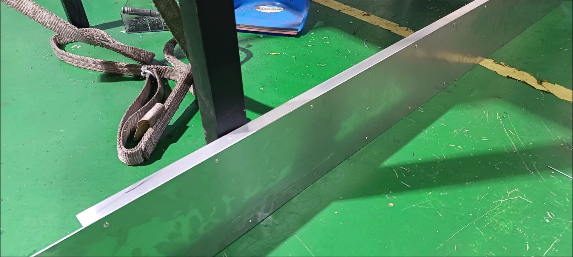
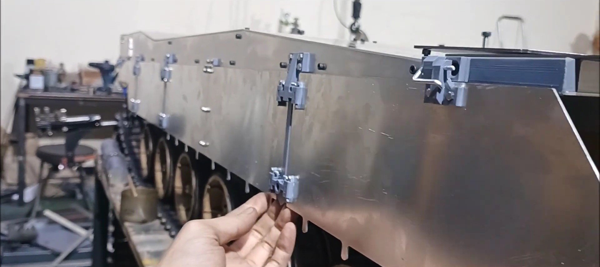
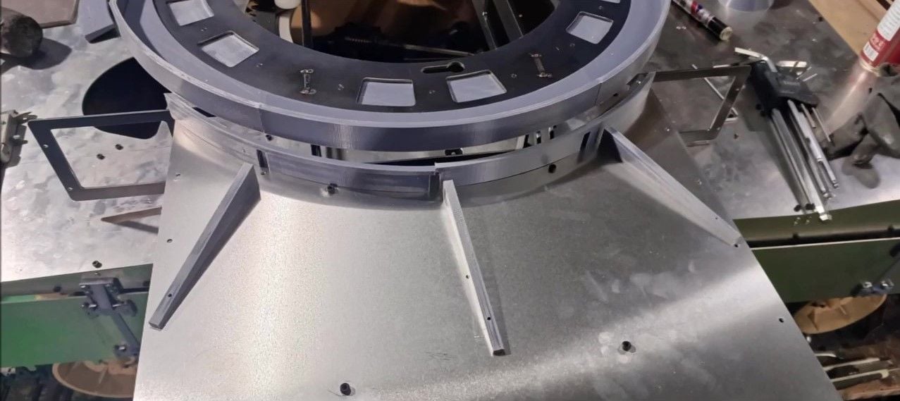
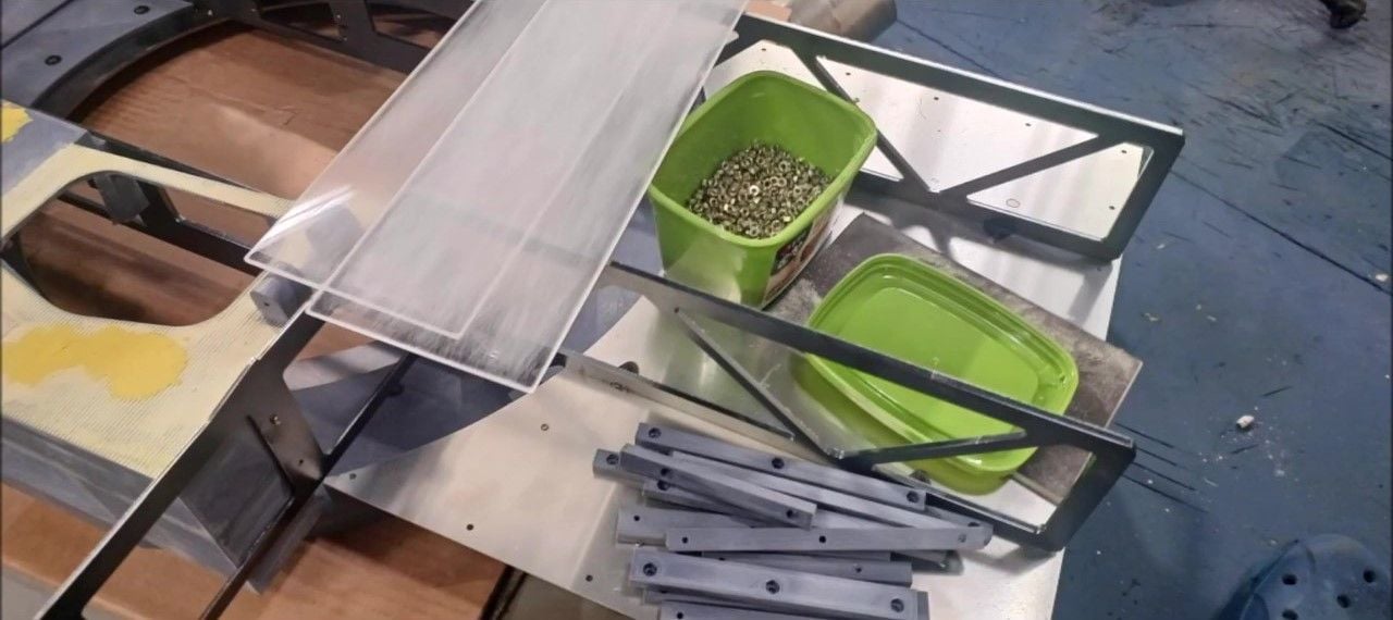
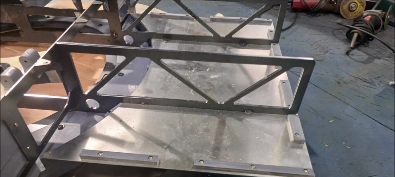
Use 1.5mm aluminum angles and aluminum panels. Unlike the main structural materials that use steel, the materials that make up the appearance due to the limit of weight are made of aluminum
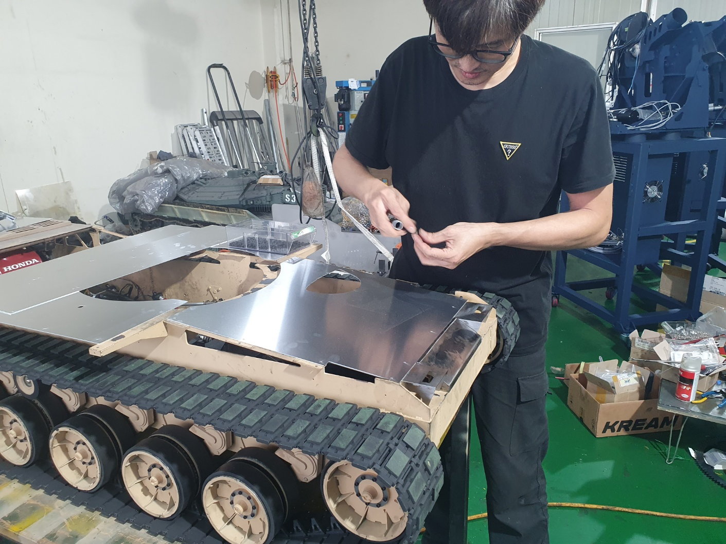
First, secure the aluminum angles to the left and right sides to match the design length.
The aluminum angle was fixed with a bolt.
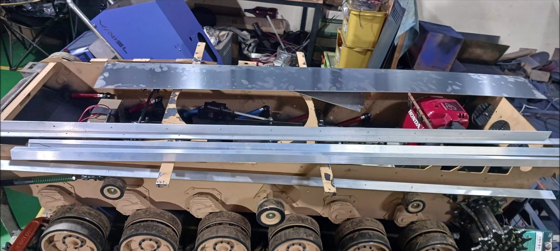
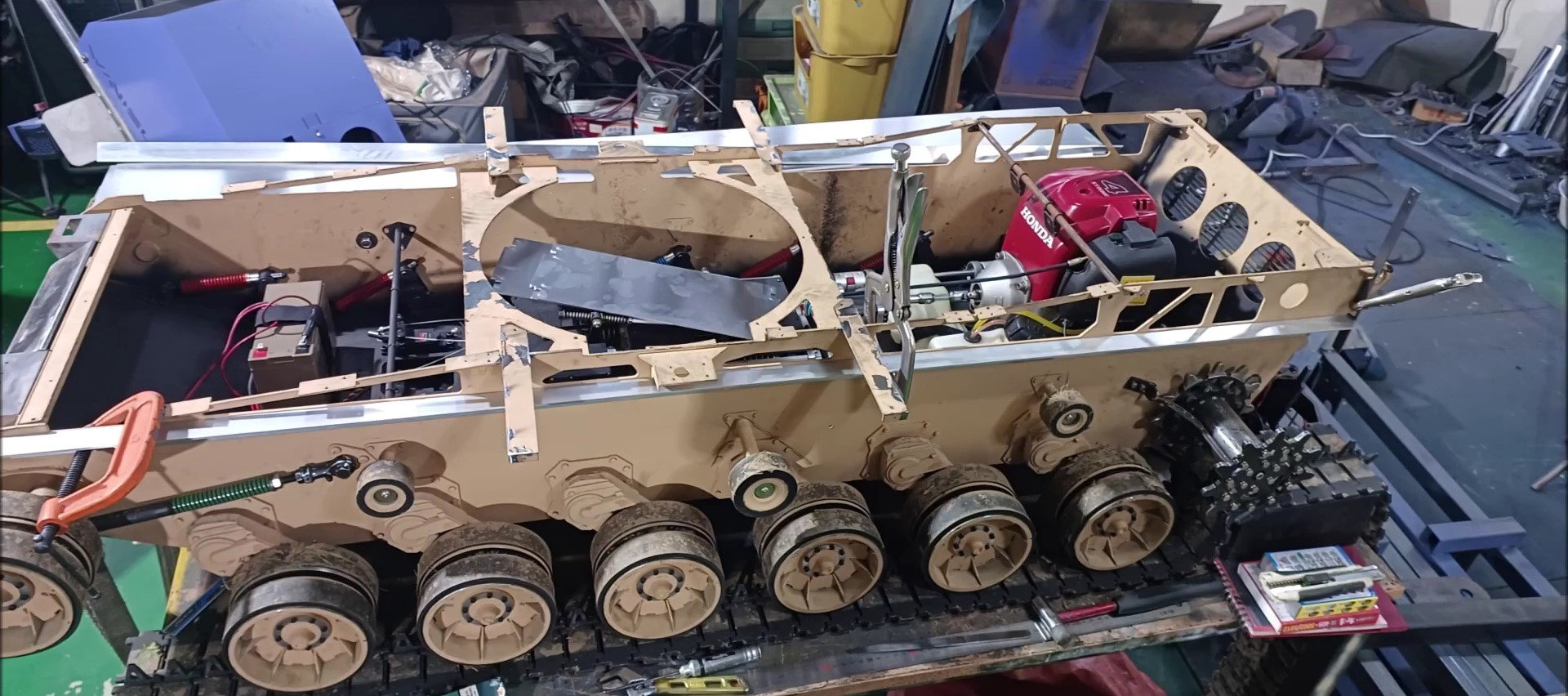
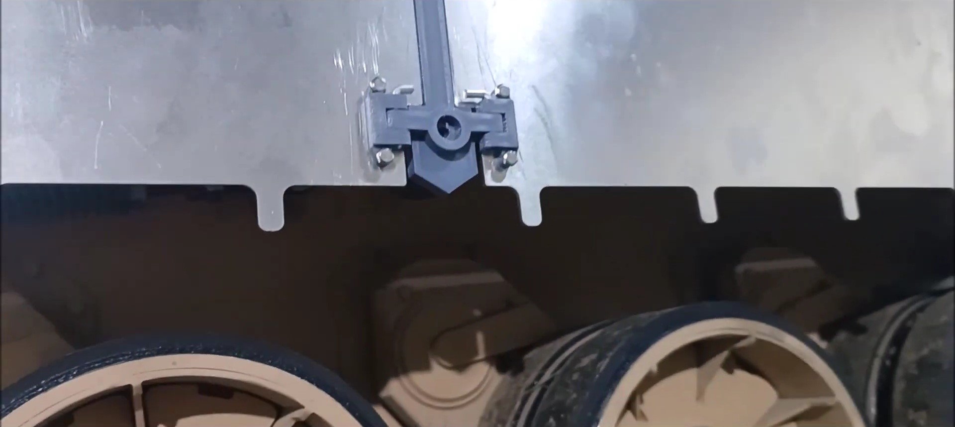
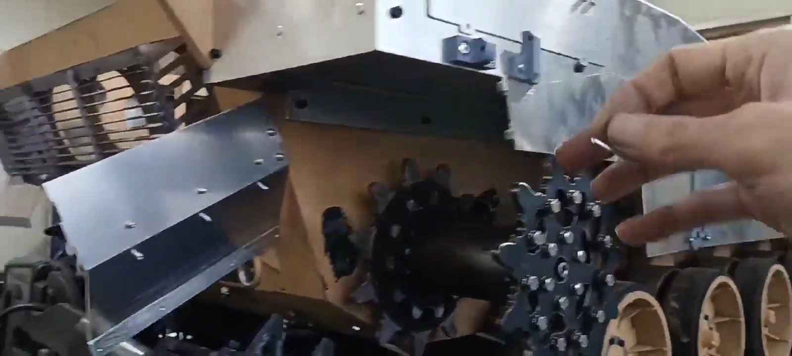
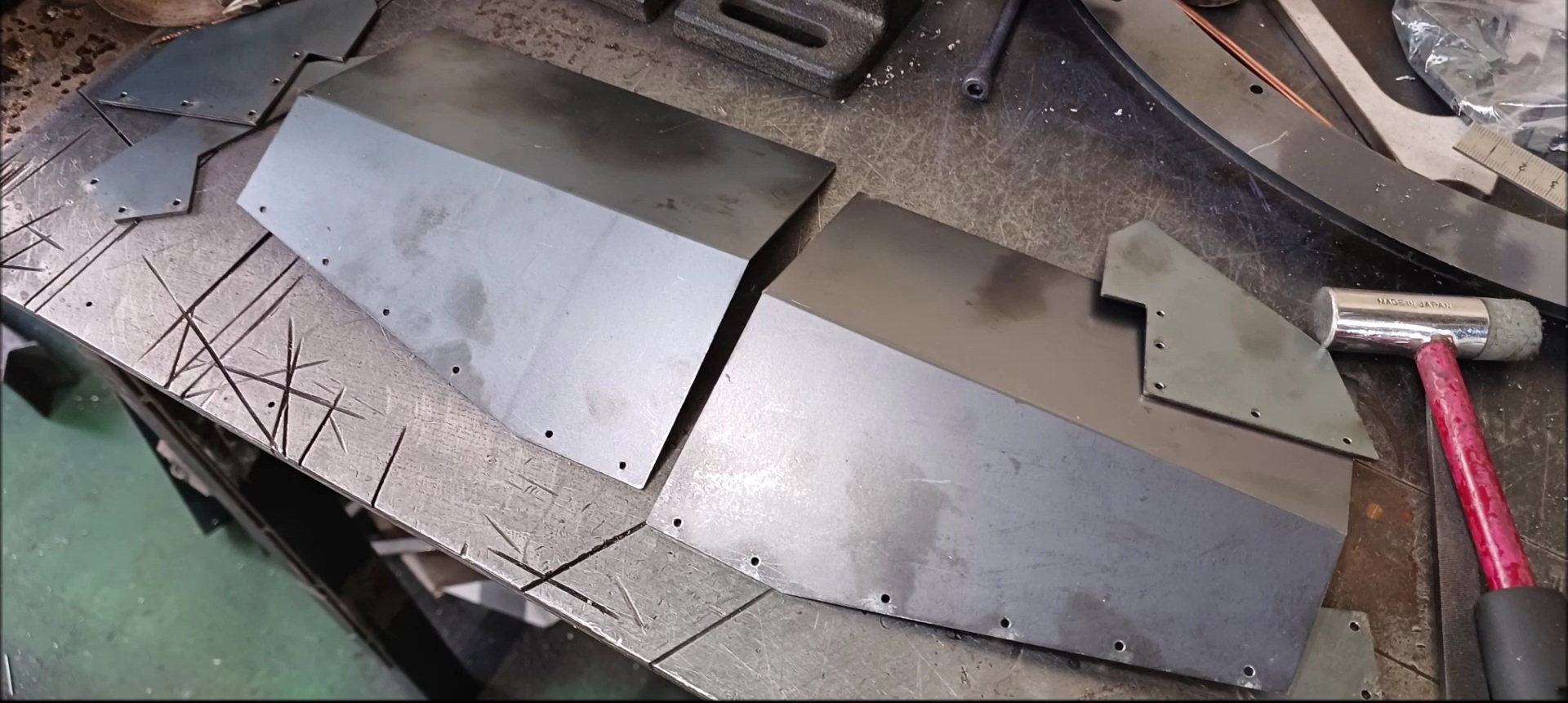
Prepare the caterpillar upper plate to be connected to the angle.
The connection between the caterpillar upper plate and one angle was fixed using a rivet.
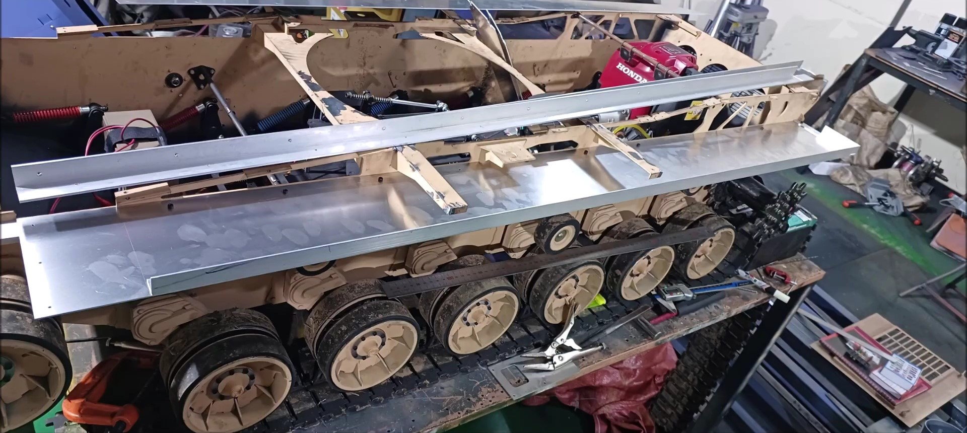
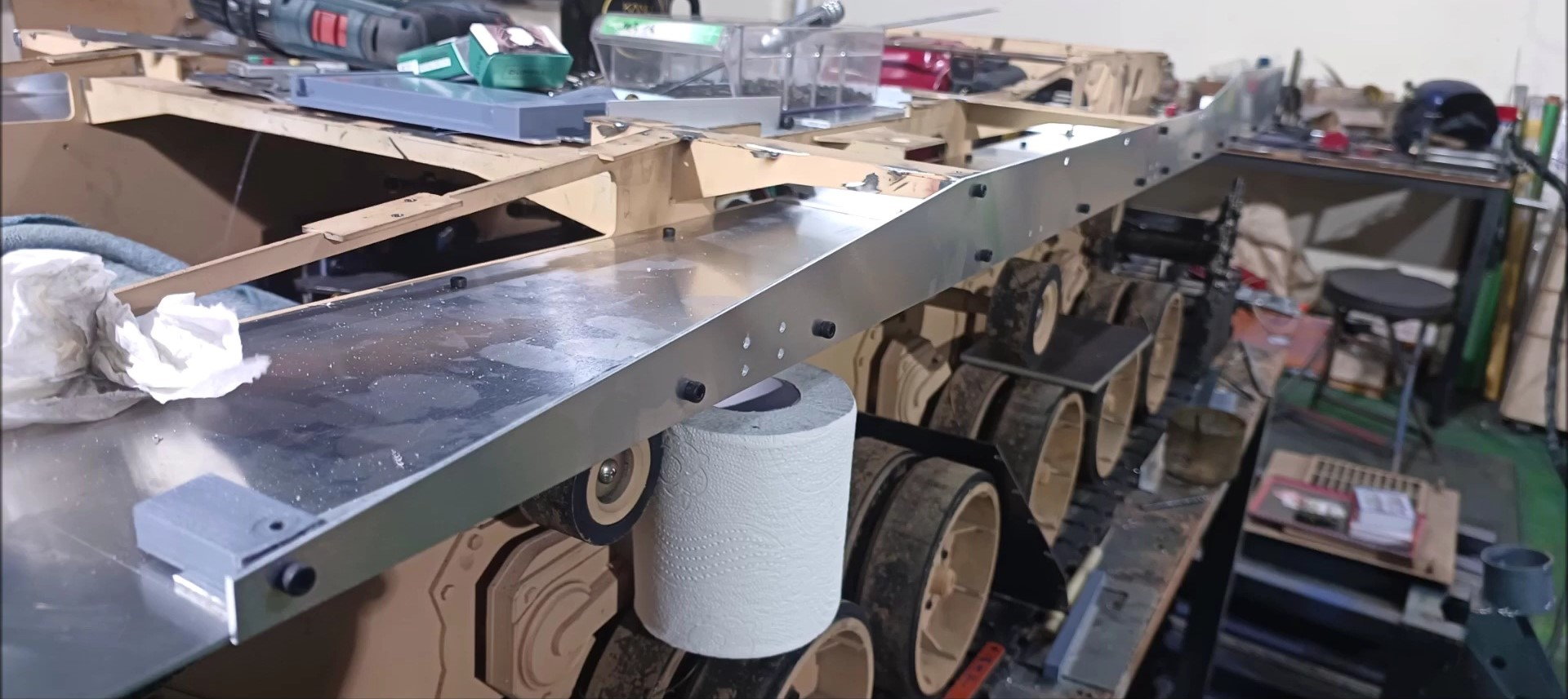
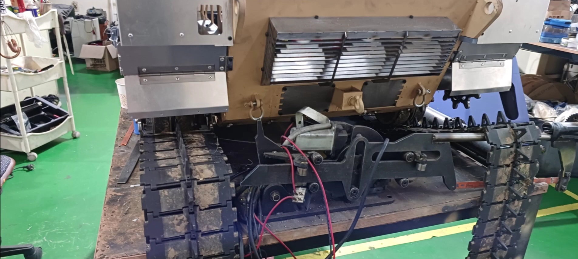
Fix the upper plate of the caterpillar to the left and right sides of the tank body.
Fix the upper plate of the caterpillar to the left and right sides of the tank body.
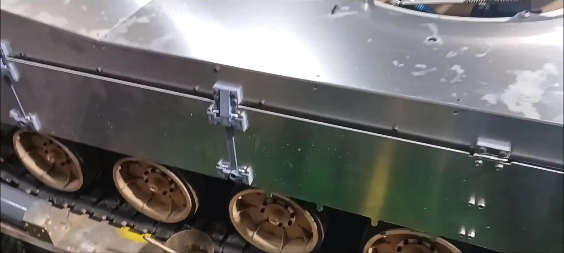
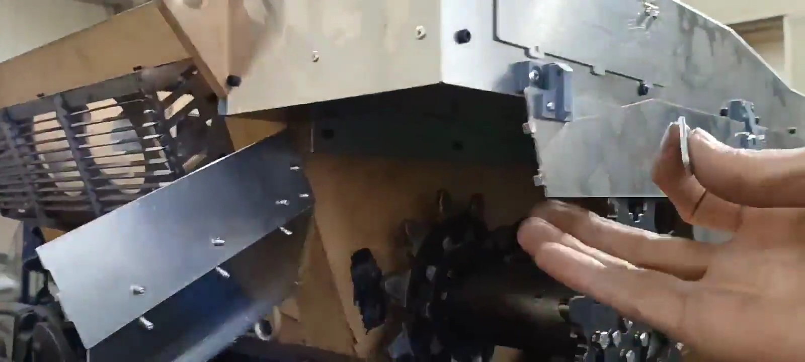
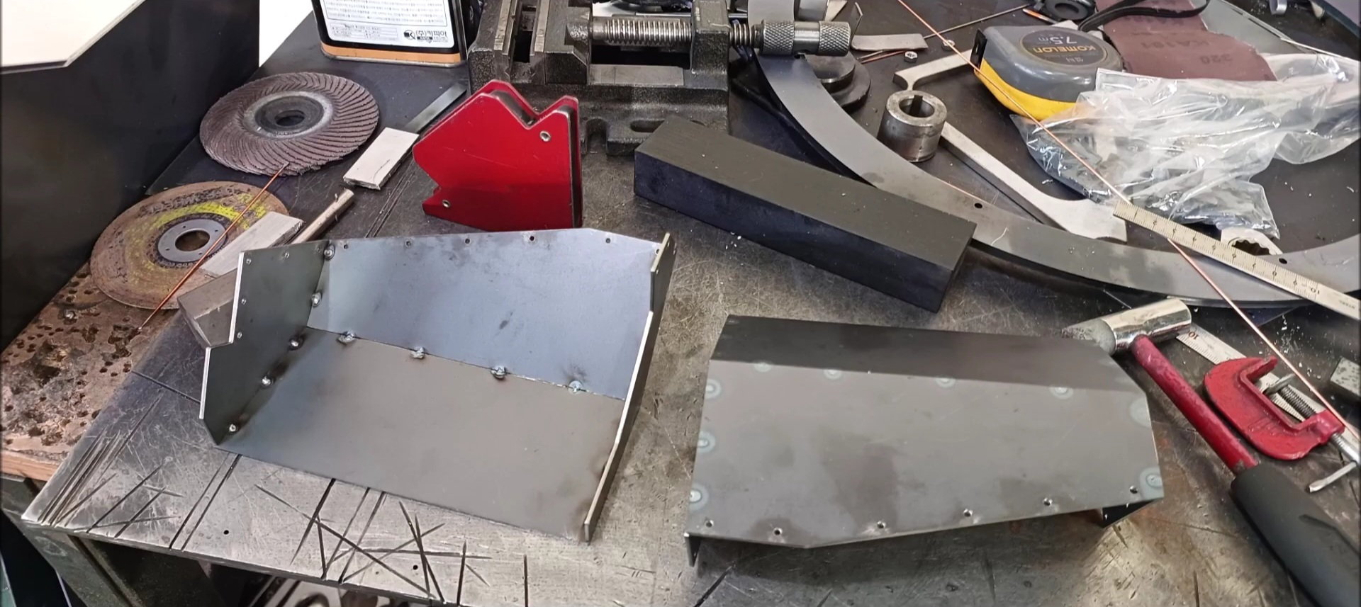
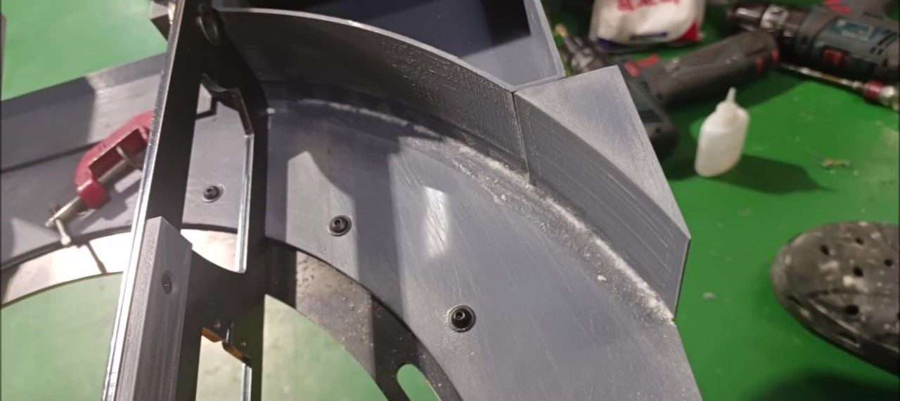
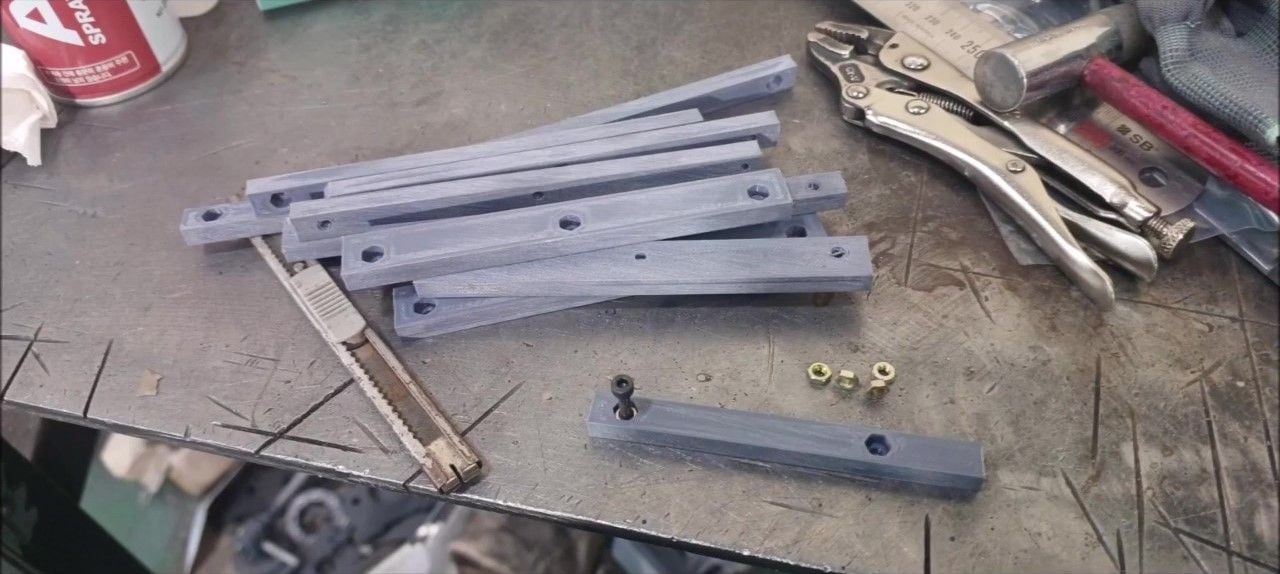
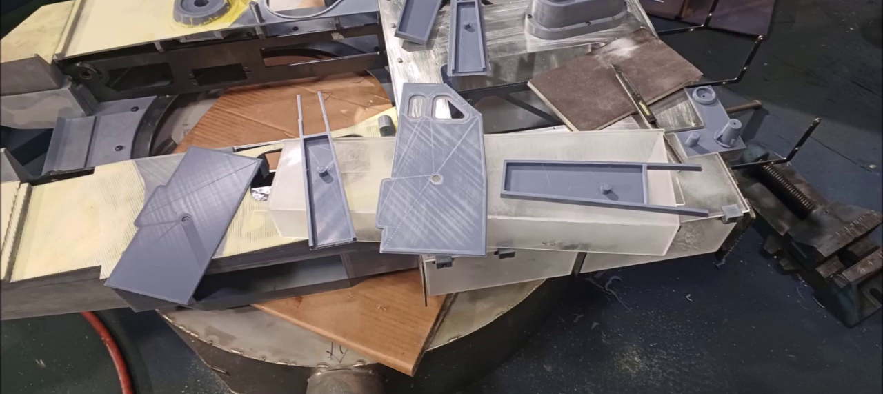
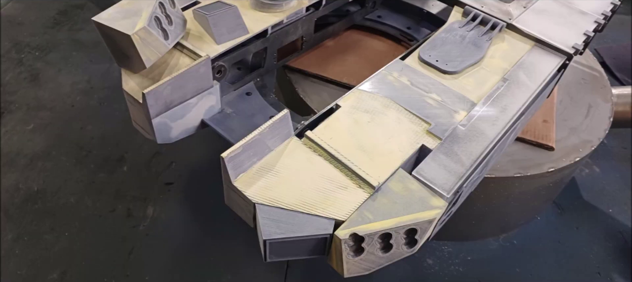
Add a 3D-printed structure to the caterpillar upper plate fixing. Secure the side plate here. Fix with screws.
Add a 3D-printed structure to the caterpillar upper plate fixing. Secure the side plate here. Fix with screws.
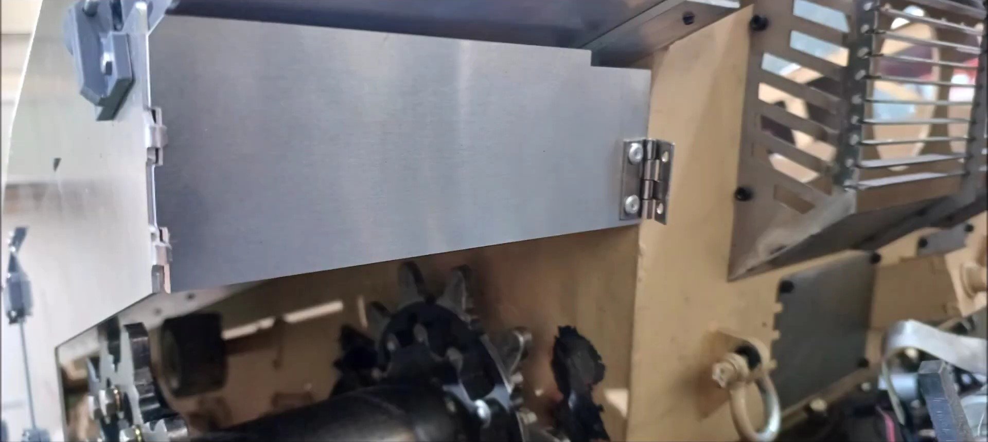
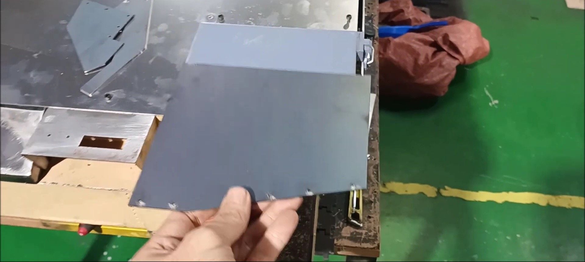
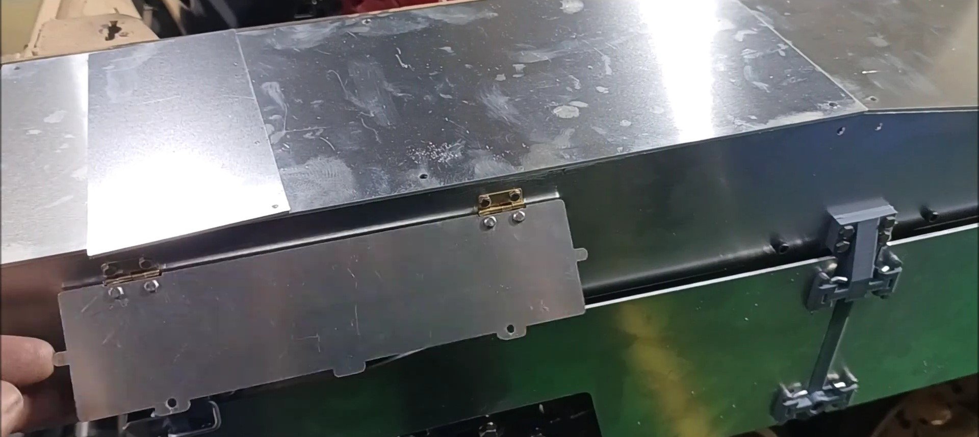
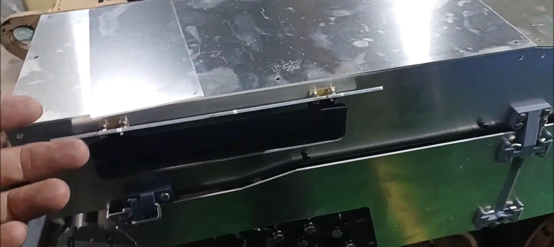
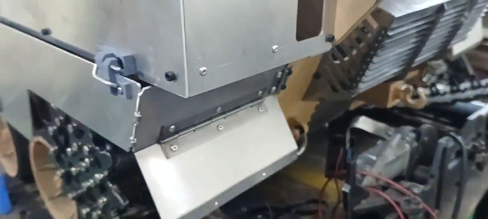
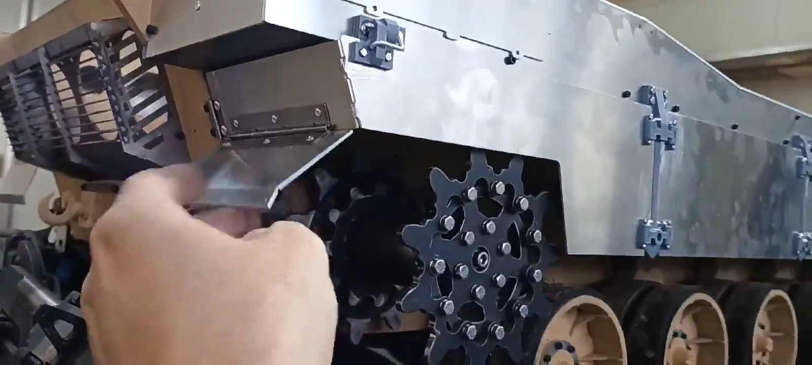
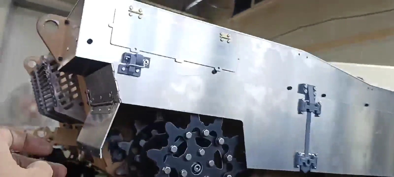
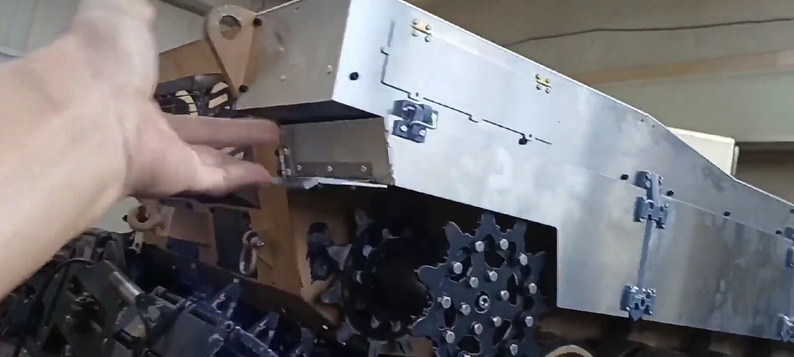
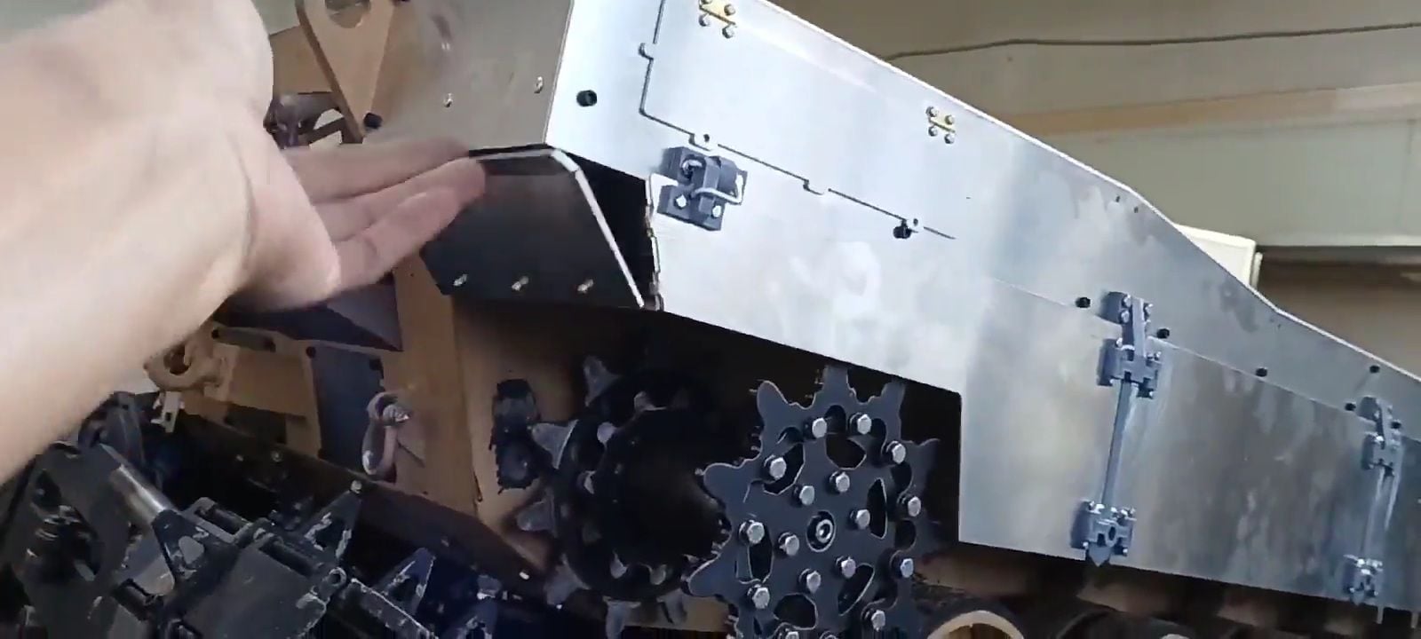
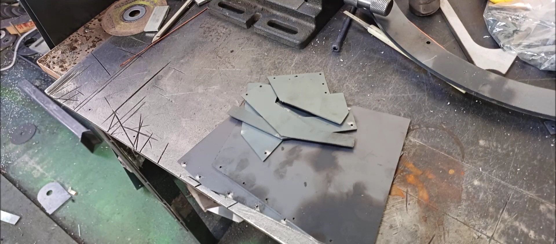
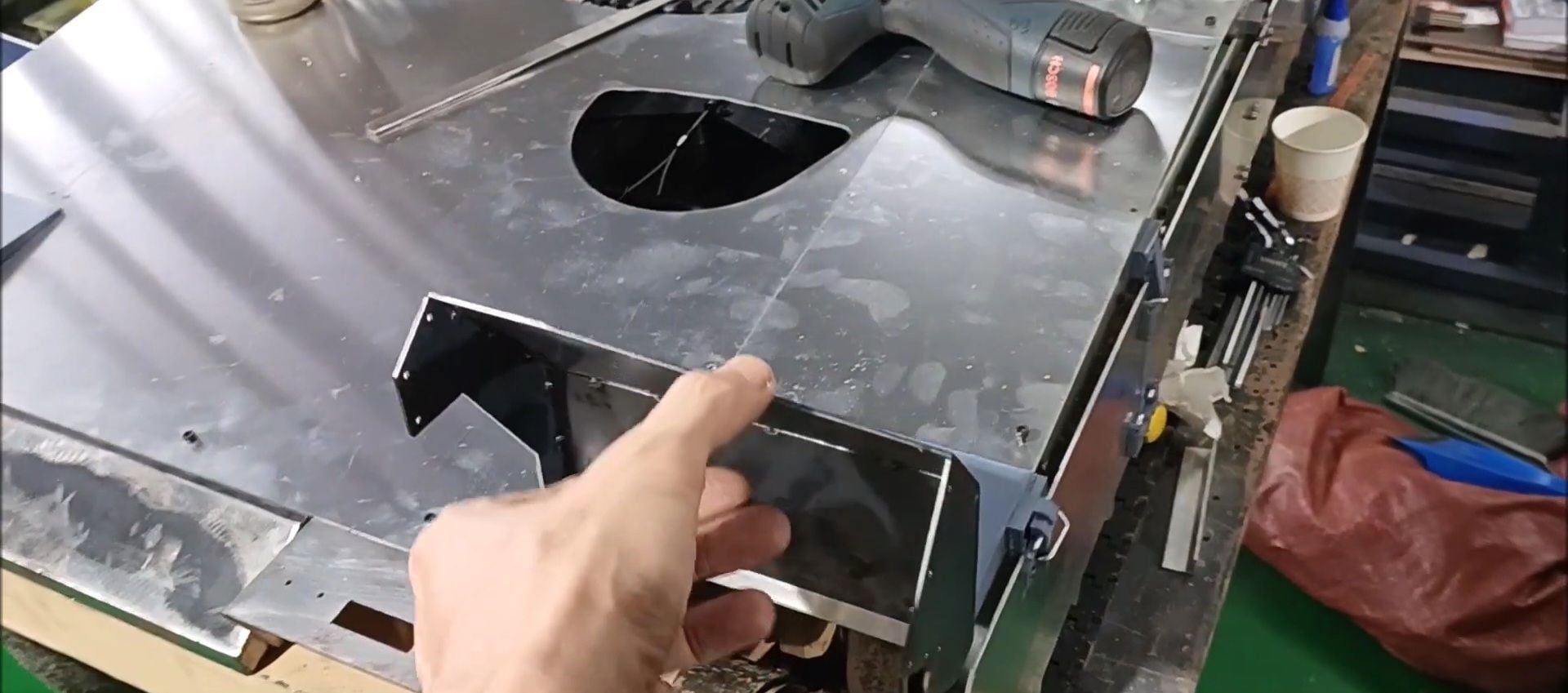
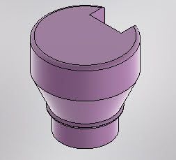
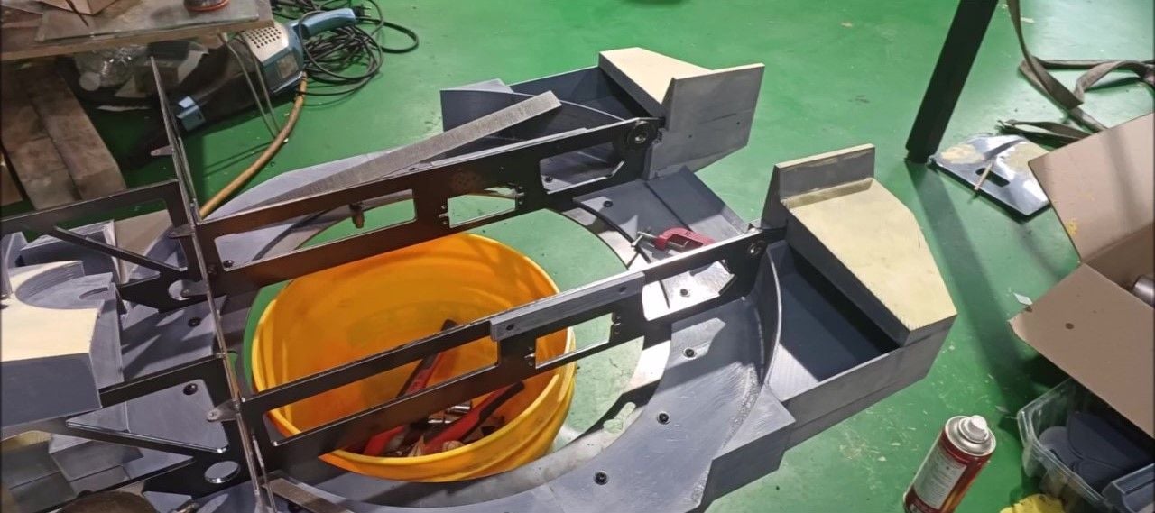
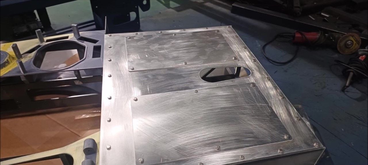
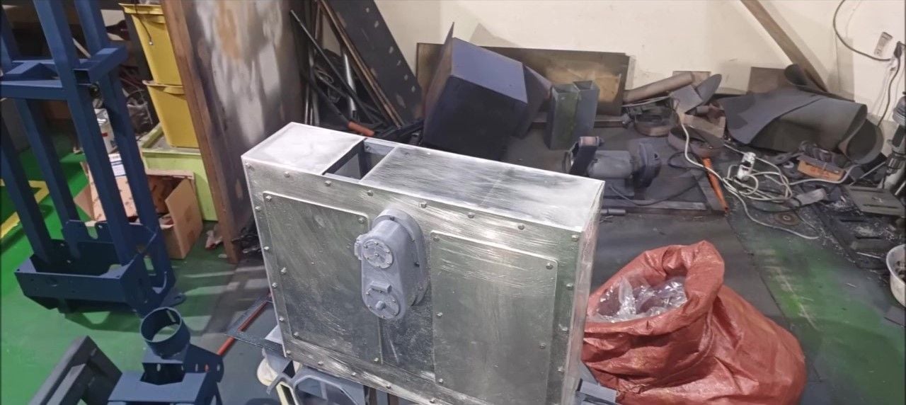
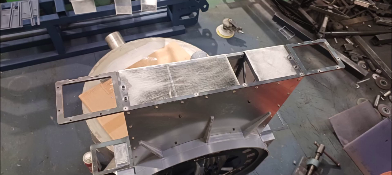
Install an engine exhaust port at the rear of the left upper plate and a plate with an inspection hole at the upper plate.
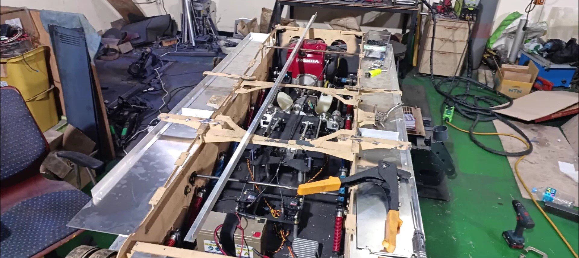
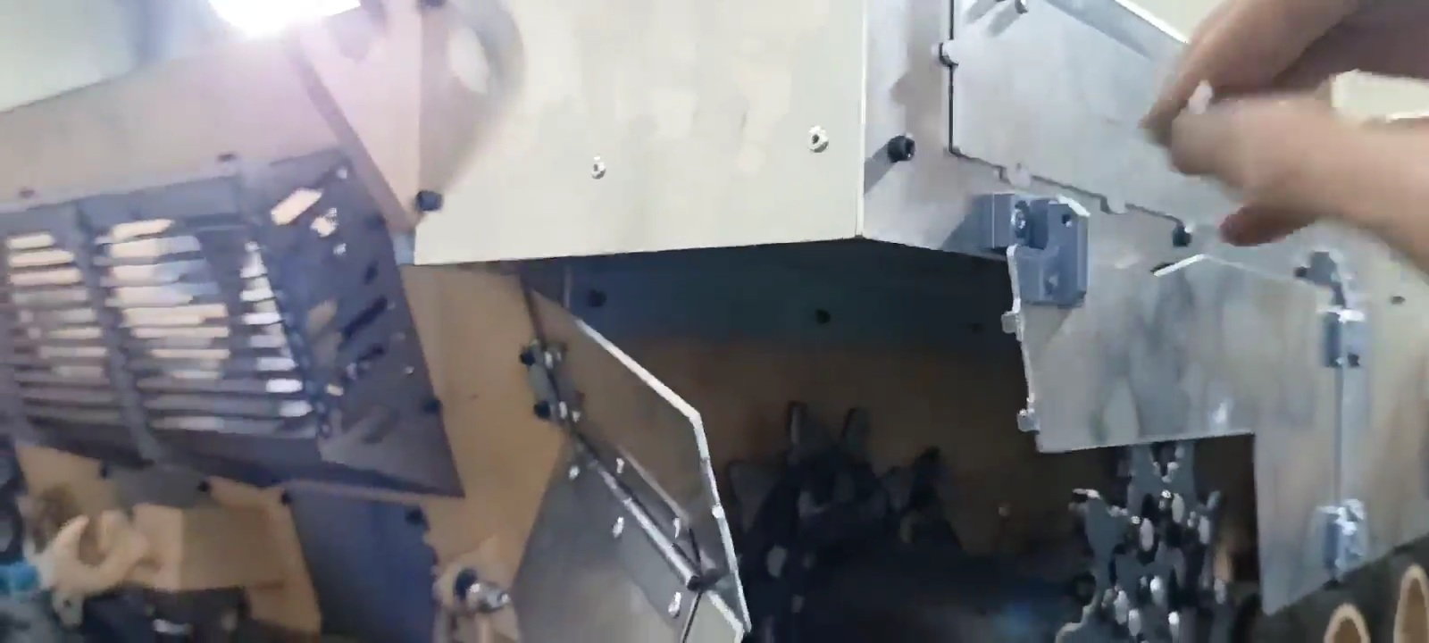
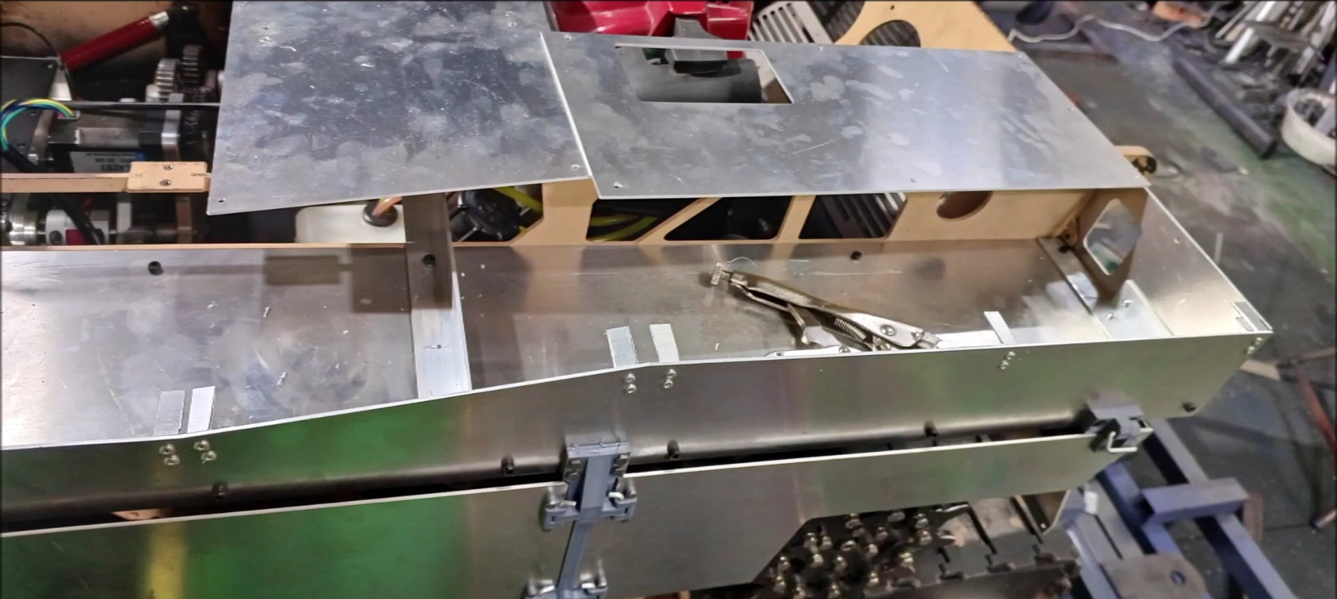
Make a temporary fix on the left side of the panel on the right caterpillar top with a vice plier and fix it with a bolt.
The left panel size of the right caterpillar top panel is different from the last version, as in the real K2, and the main power control panel will be installed at the rear right.
The size of the left panel on the right caterpillar top is different from the previous version in the left and right as in the real K2. The right side is thicker than the left back furniture.
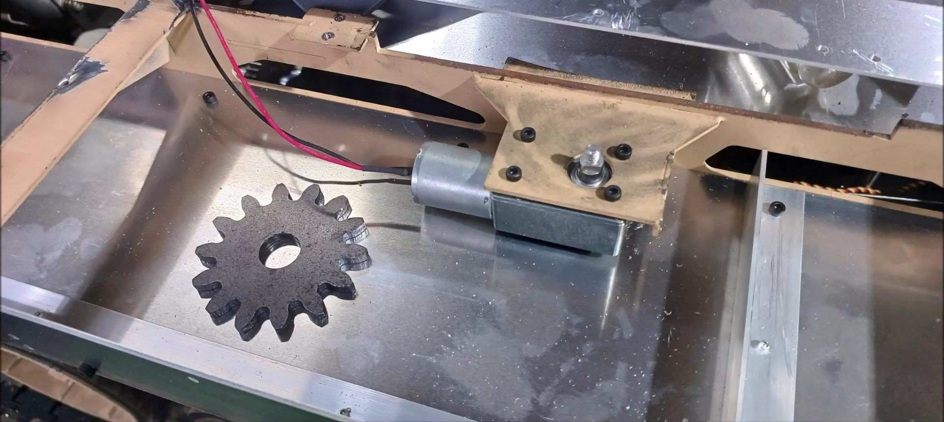
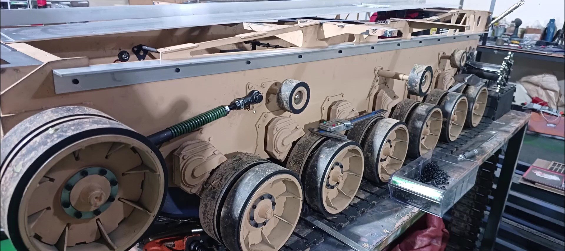
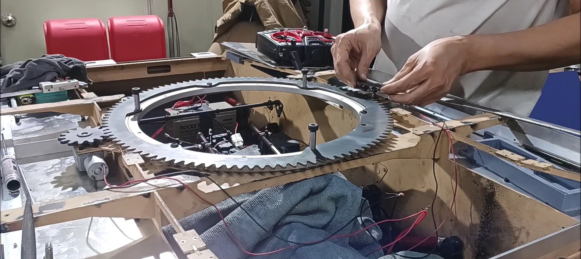
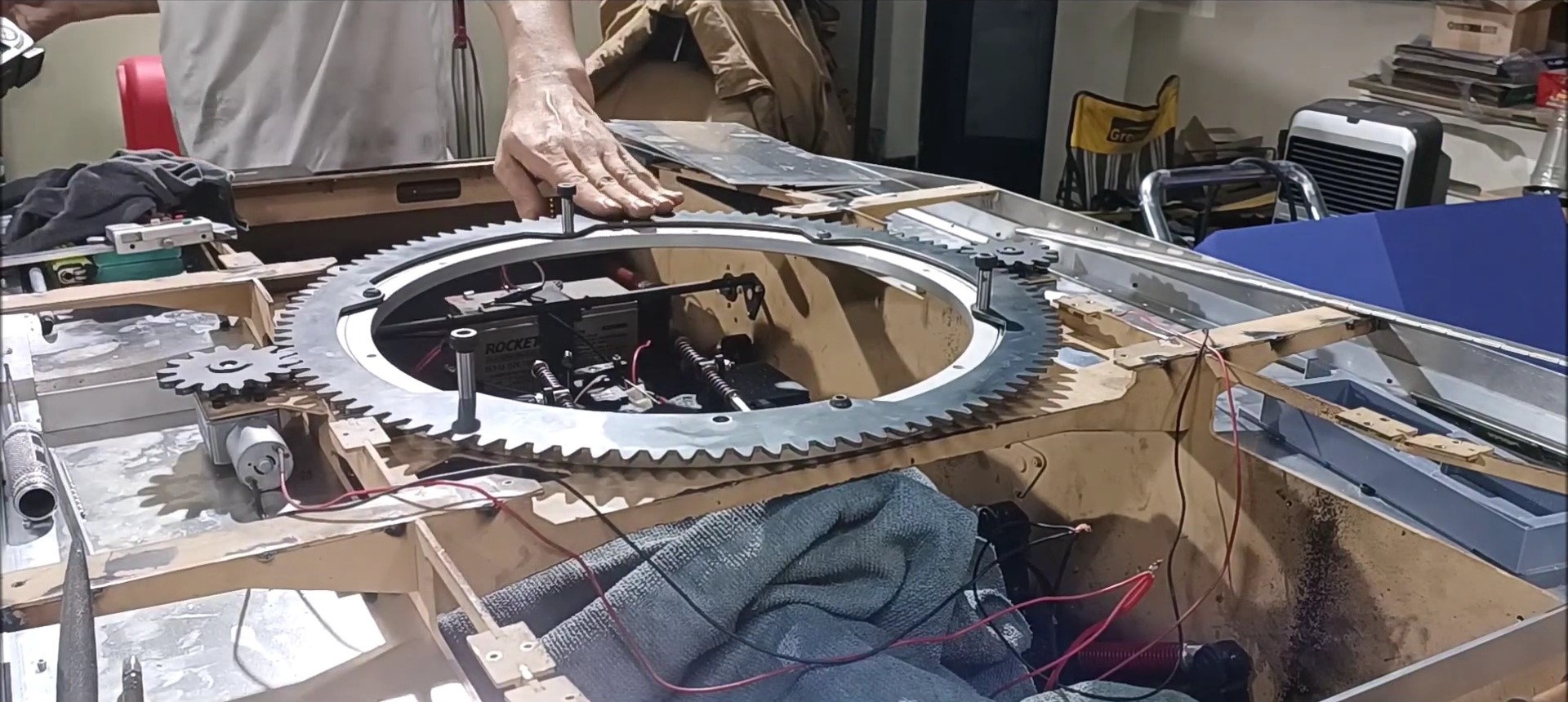
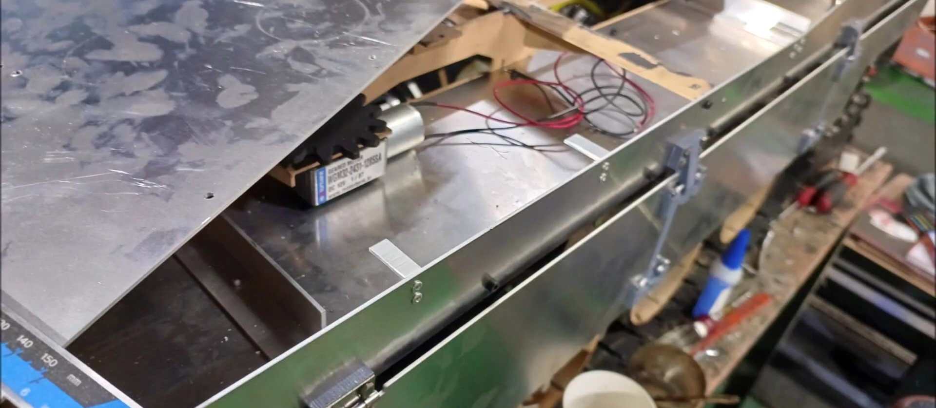
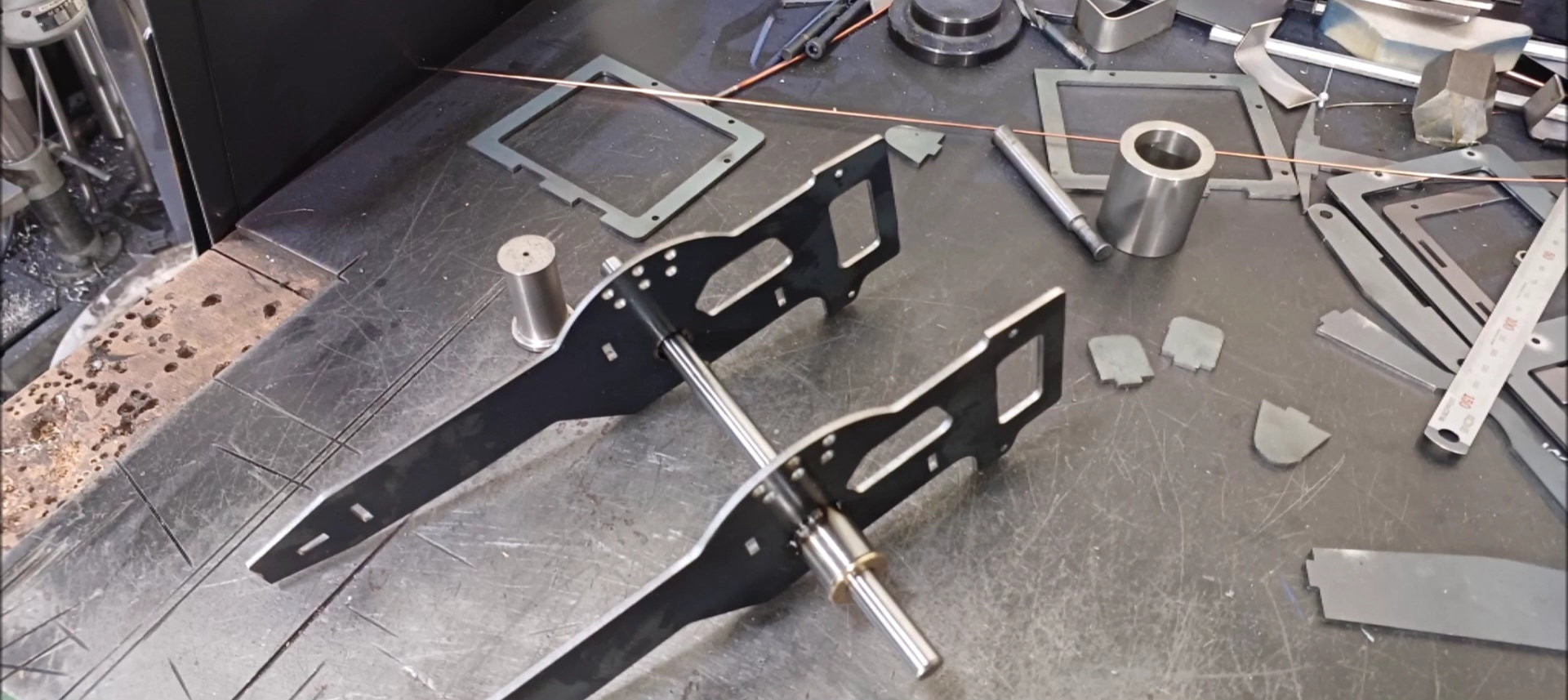
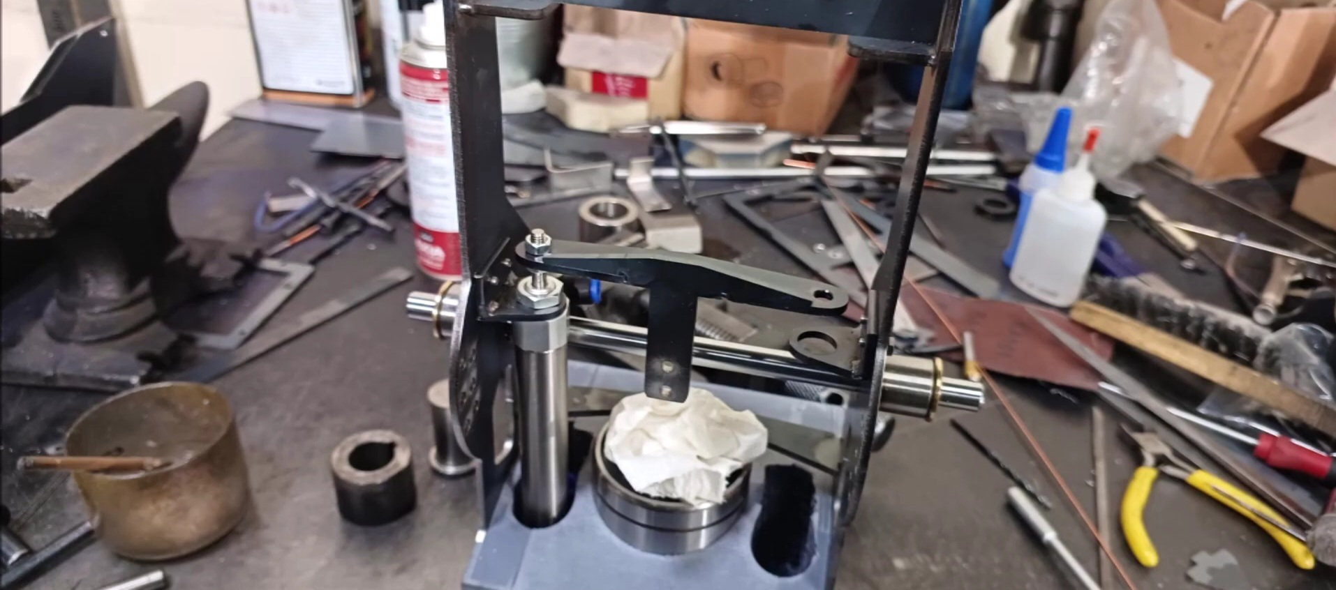
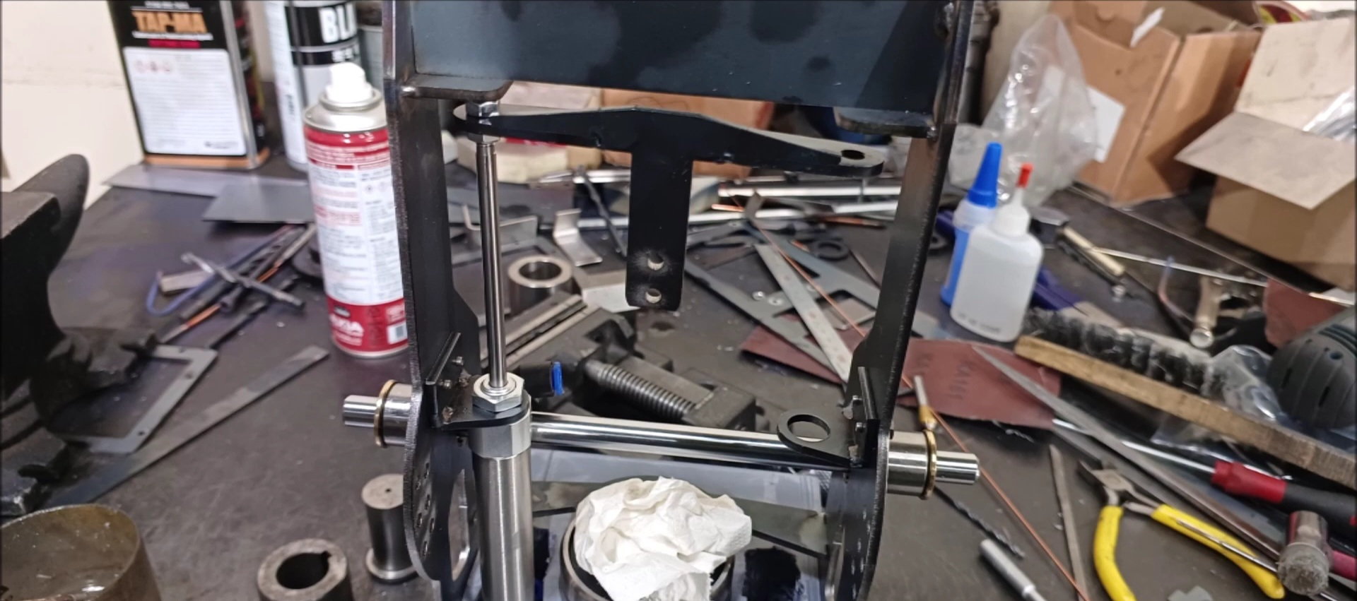
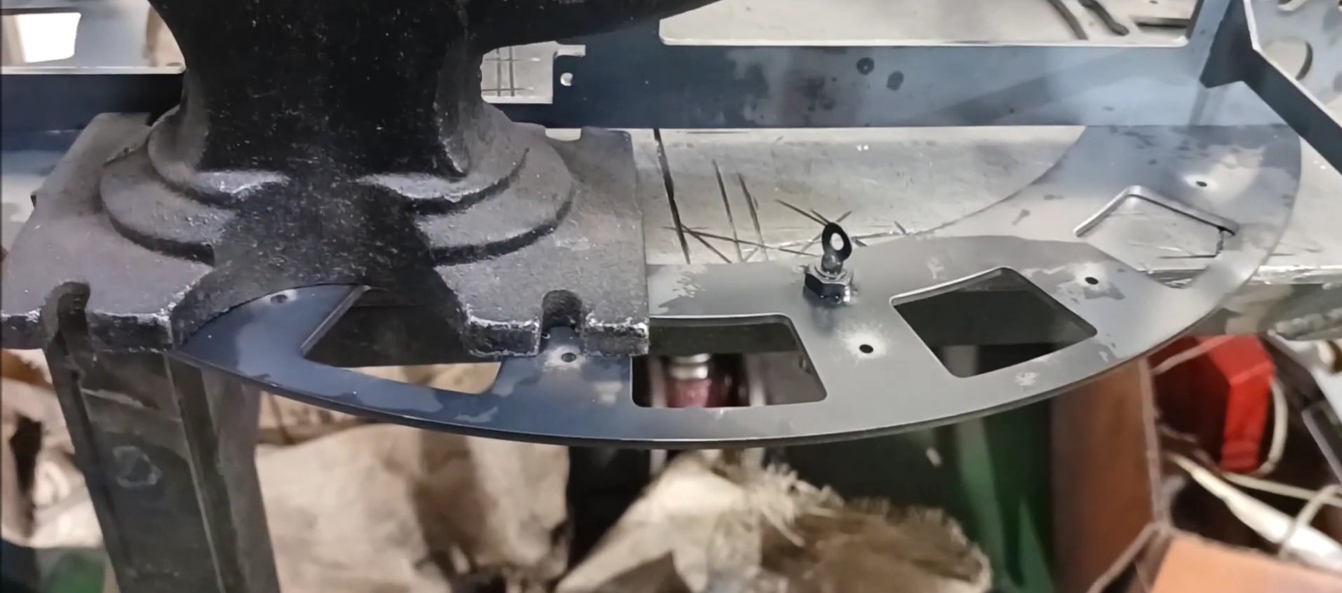
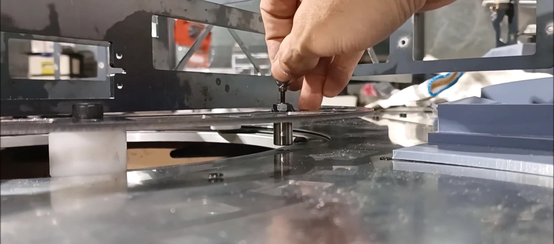
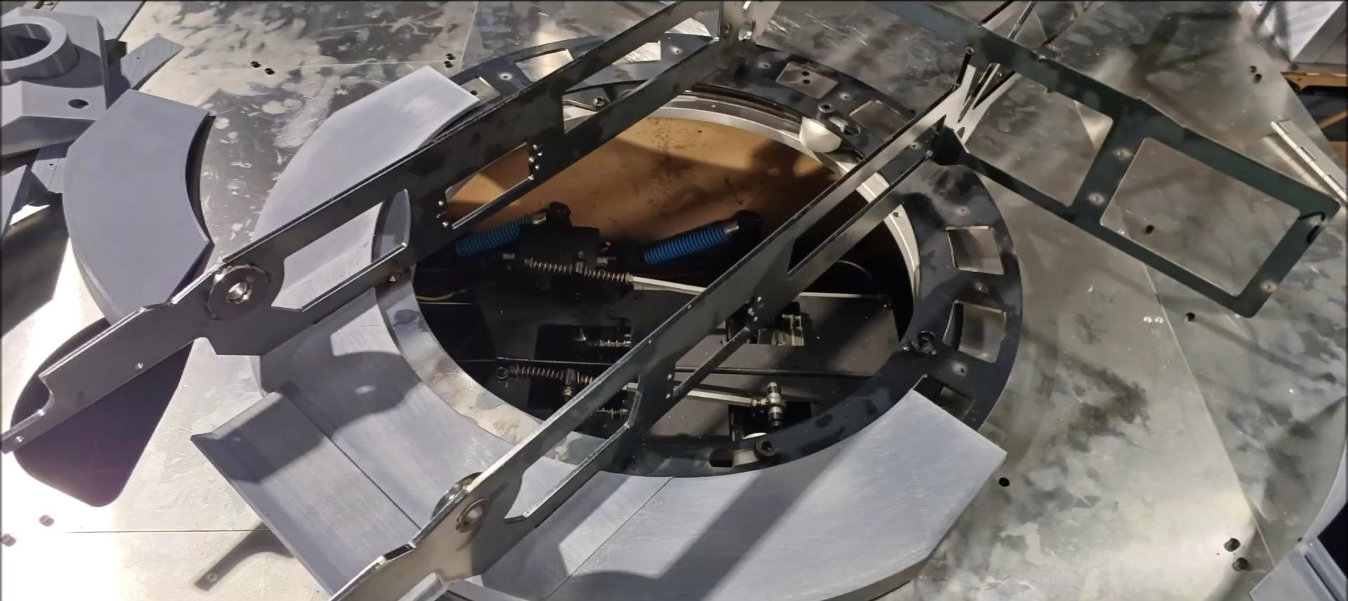
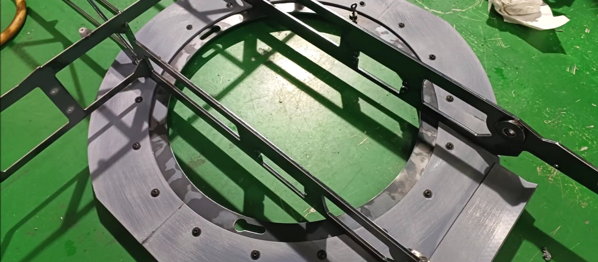
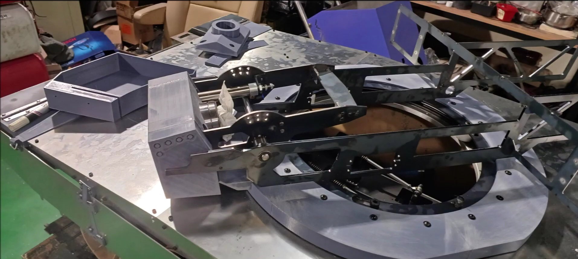
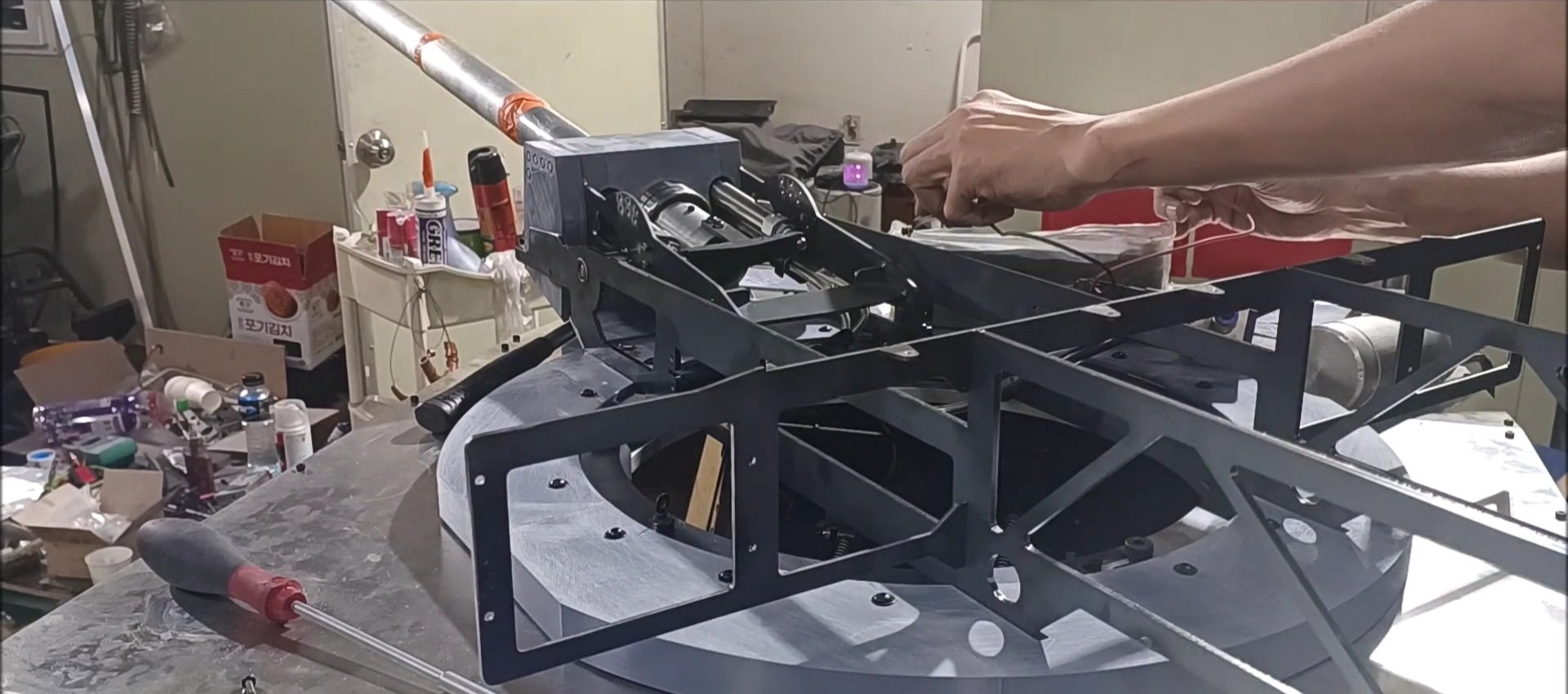
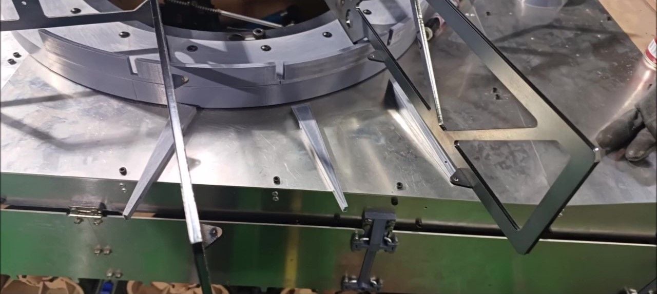
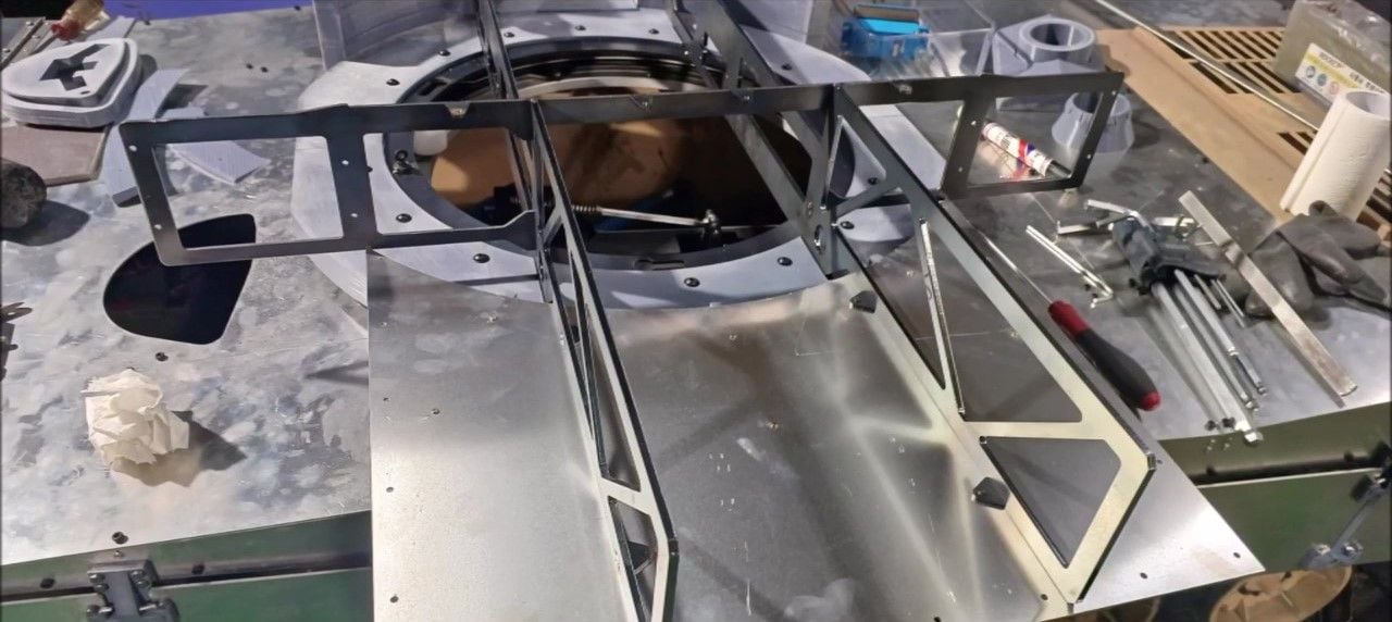
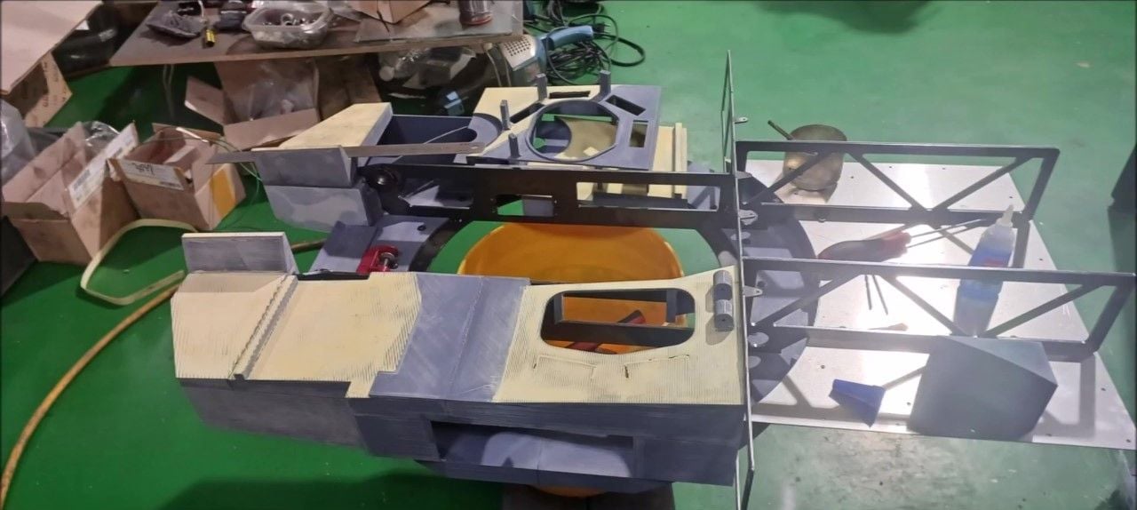
Secure the motor to the left and right to control the turret. These are geared motors.
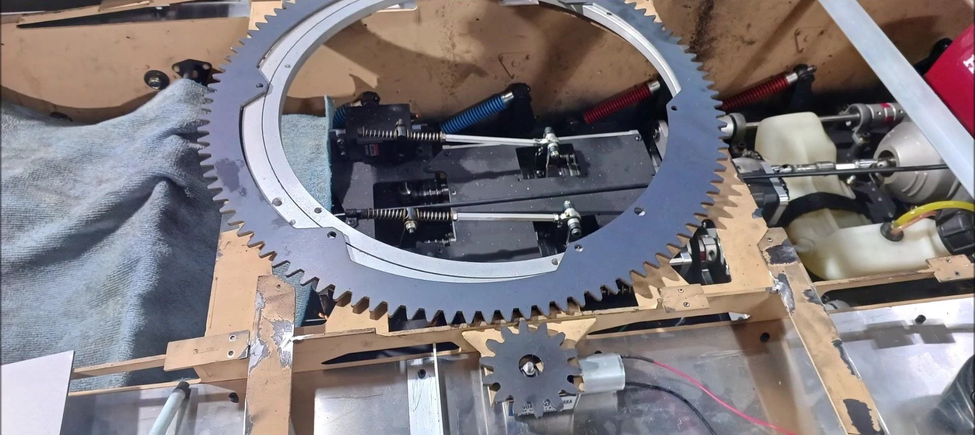
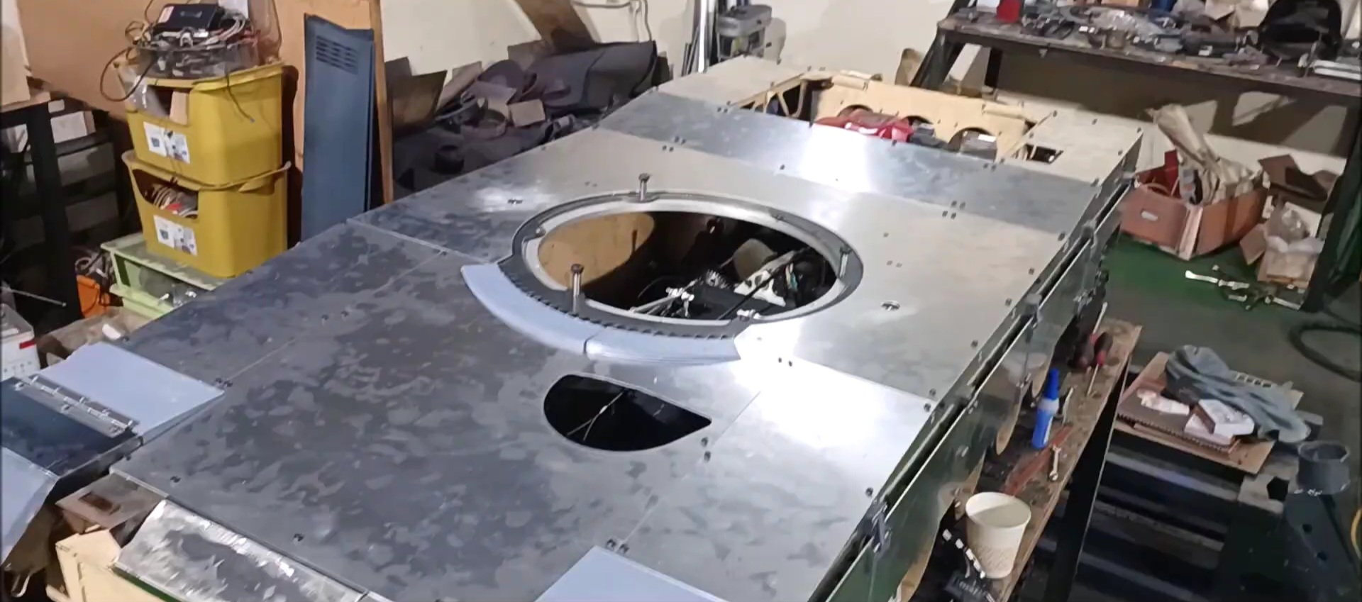
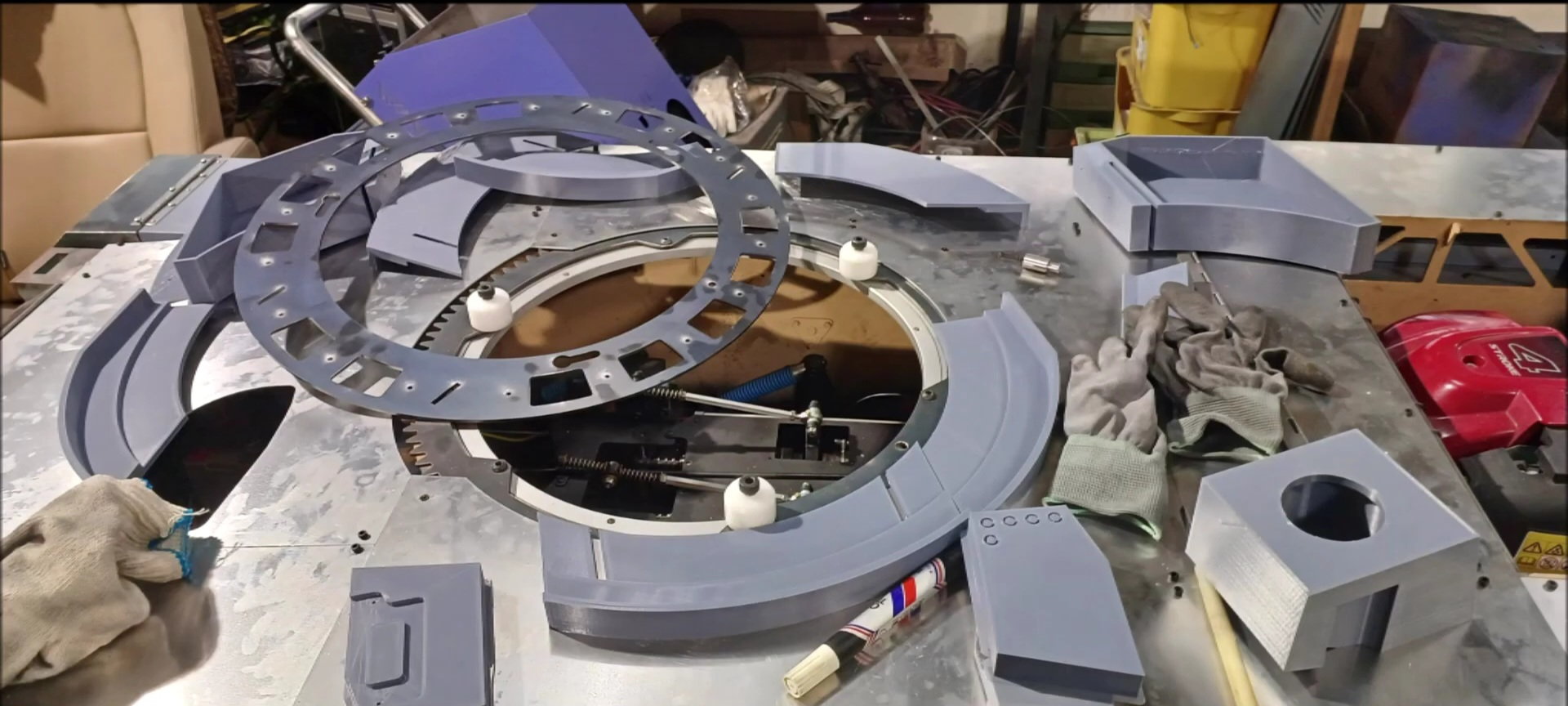
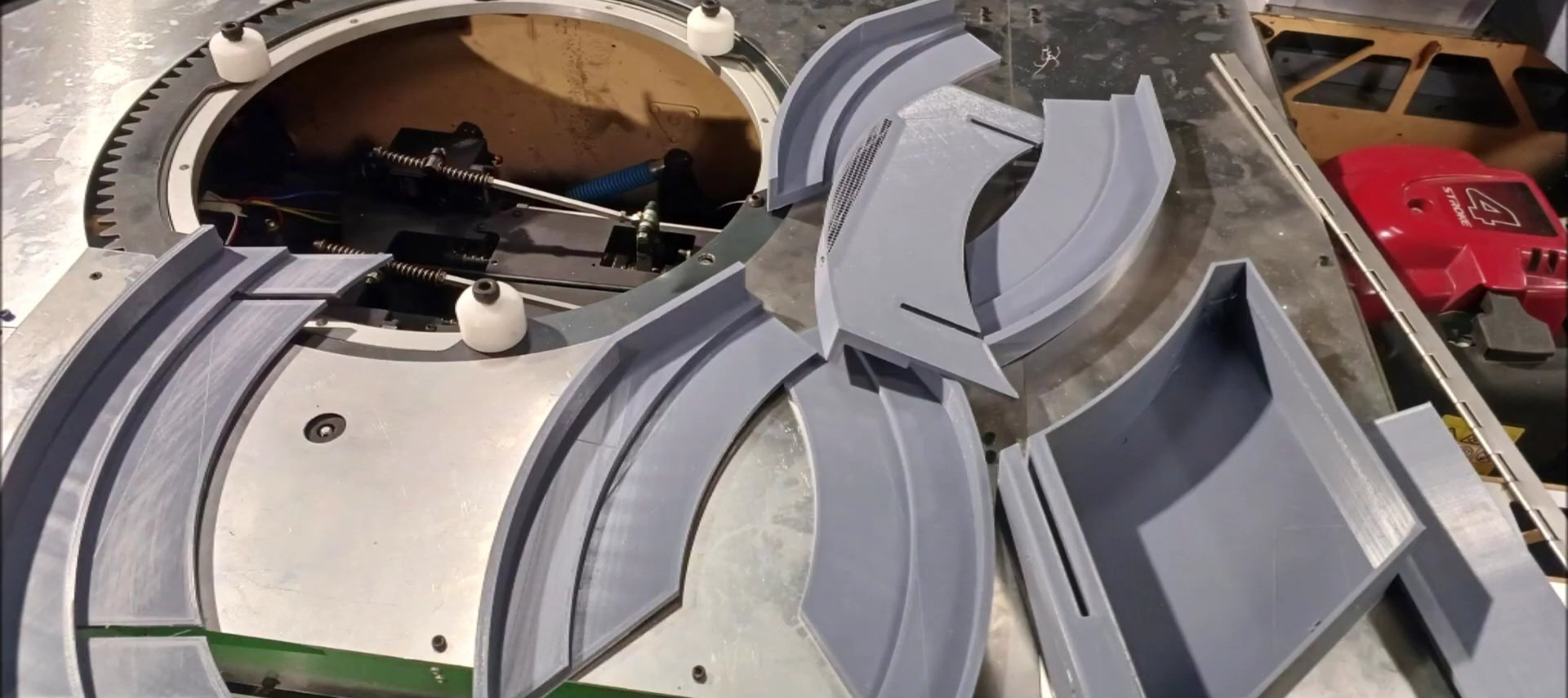
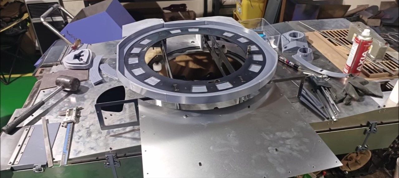
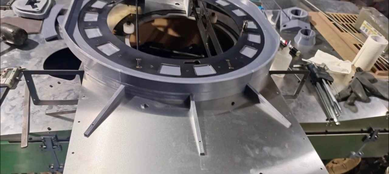
This version is an outer wheel turret, so I'll try to position it first.
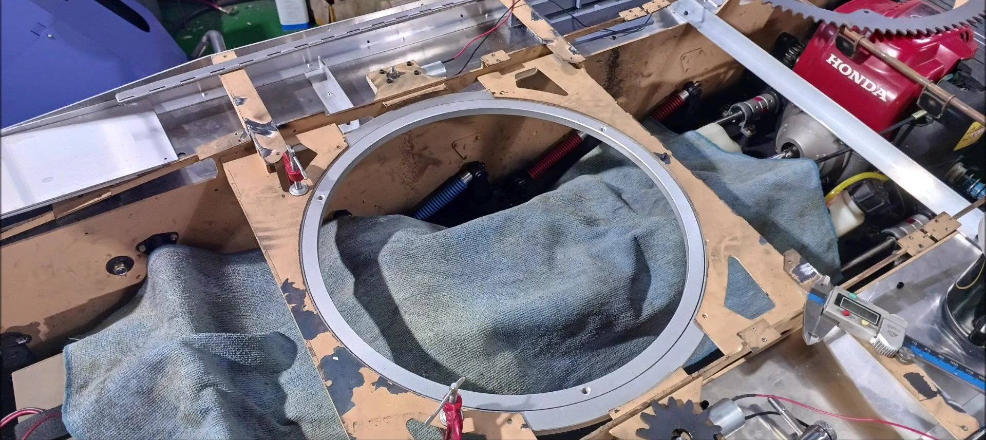
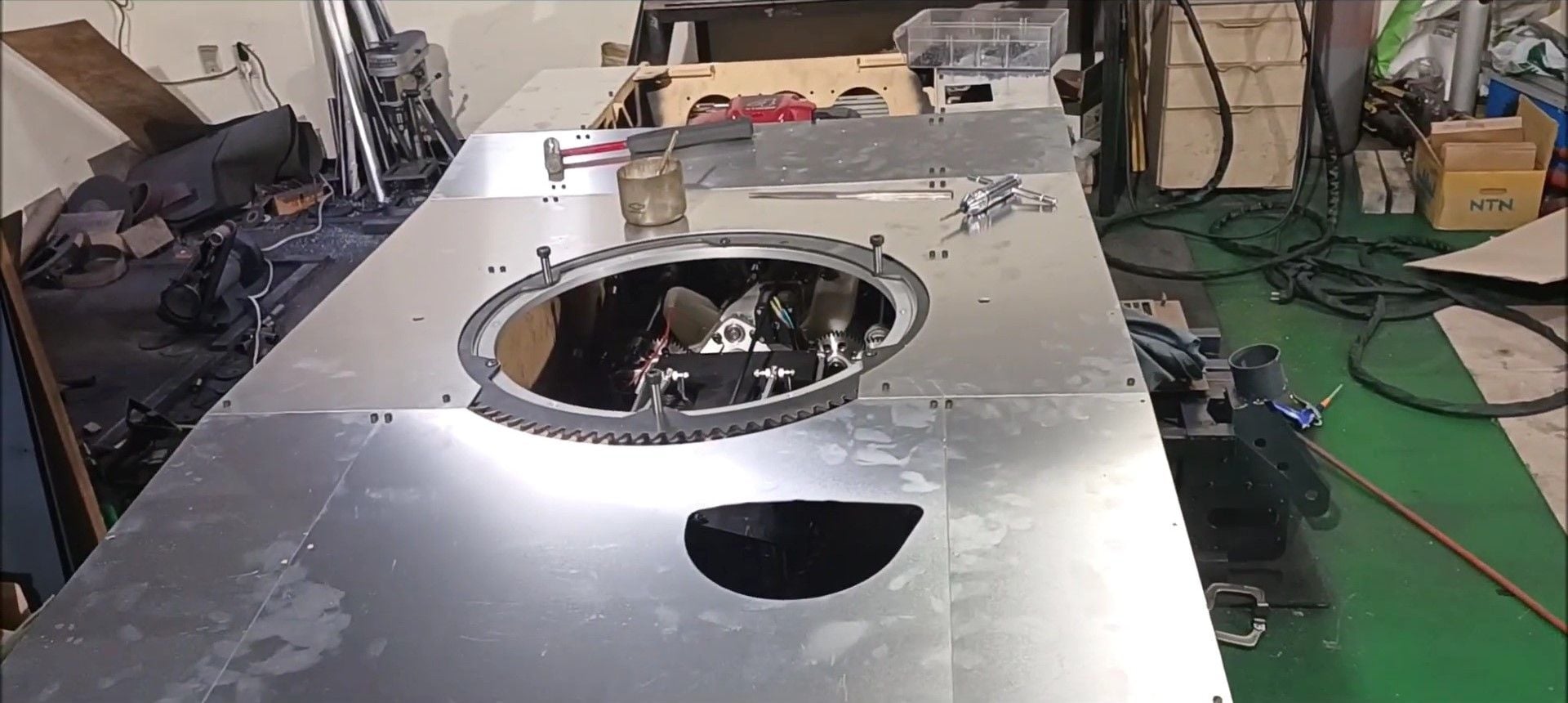
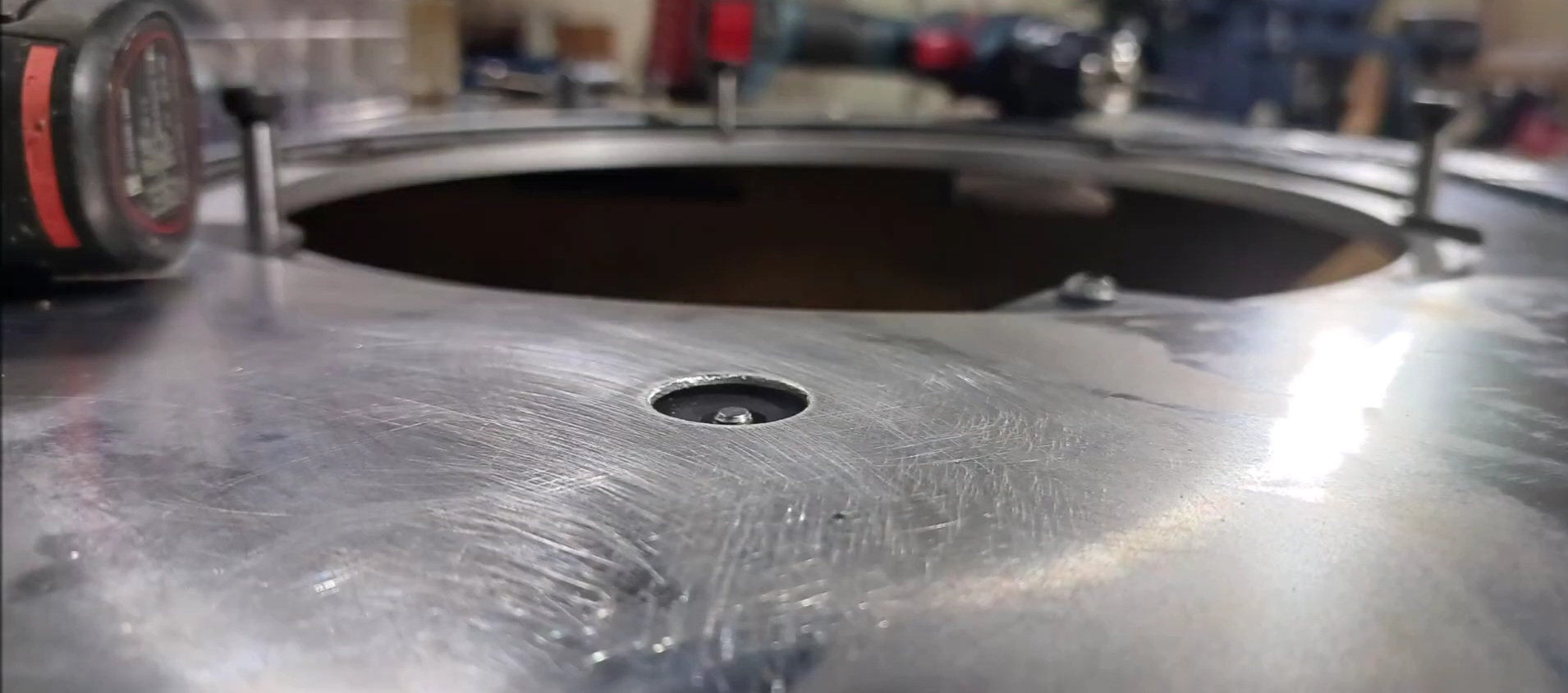
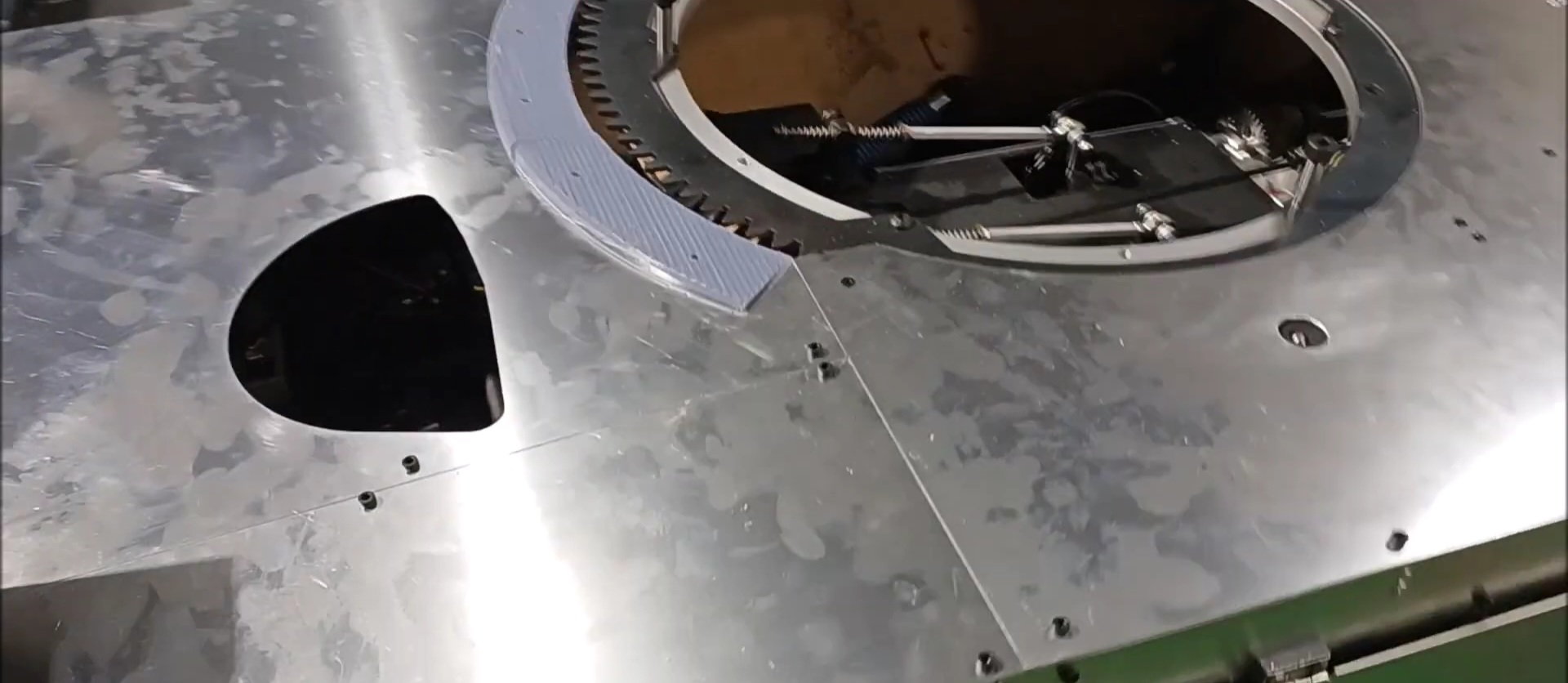
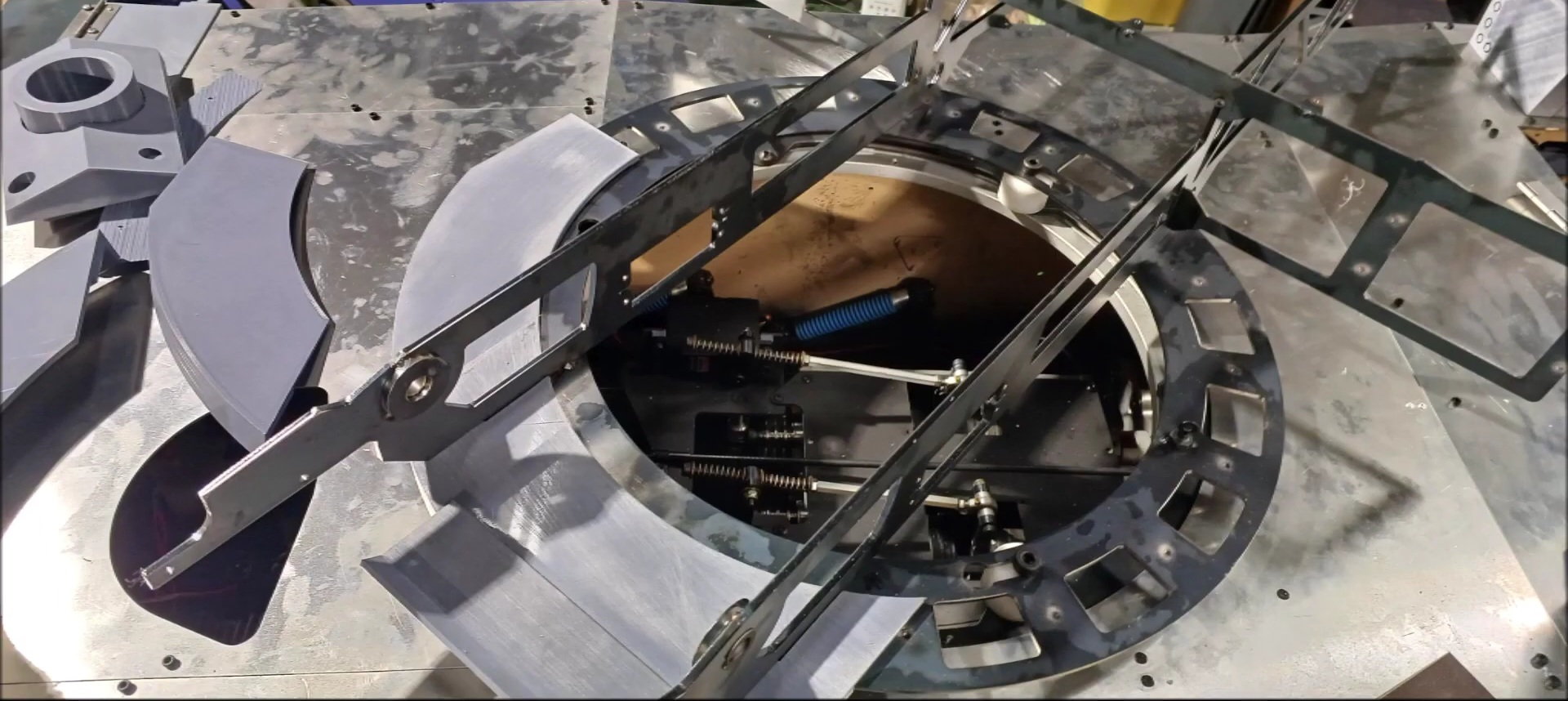
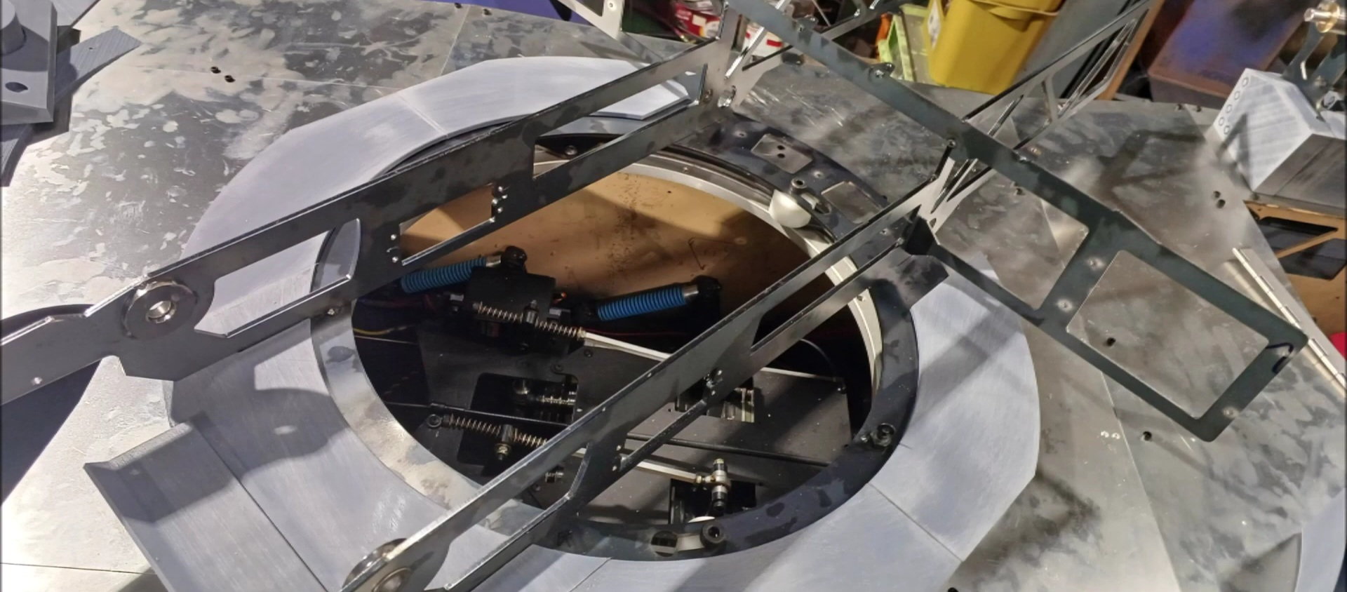
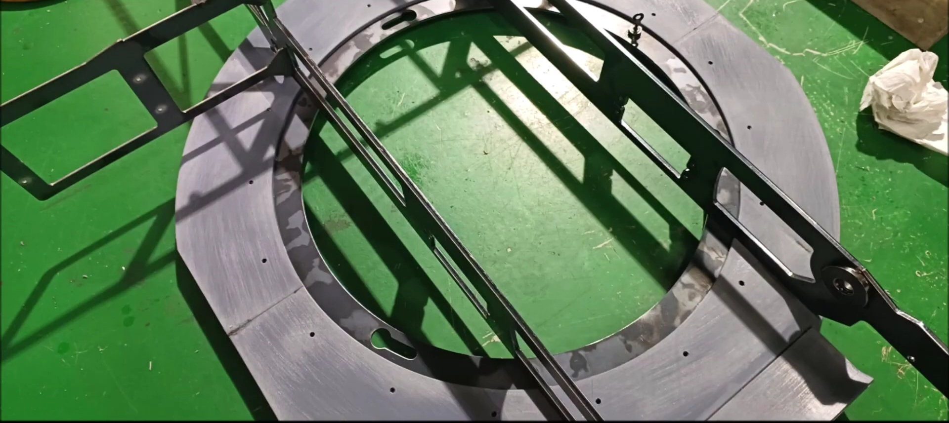
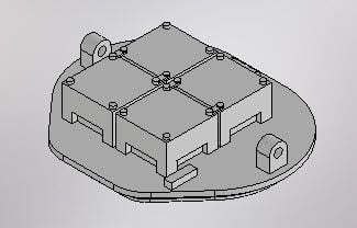
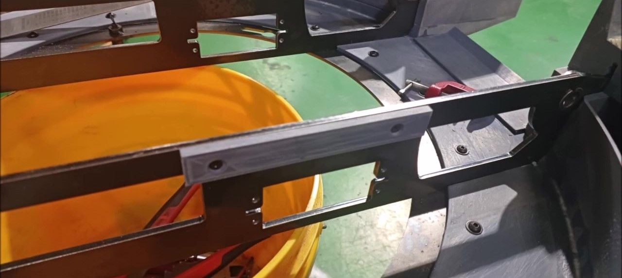
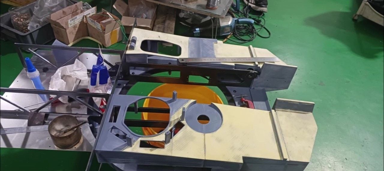
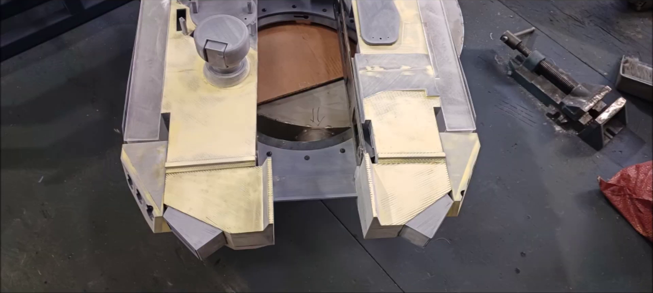
First, fix the body and LAZY SUSAN turntable ring first.
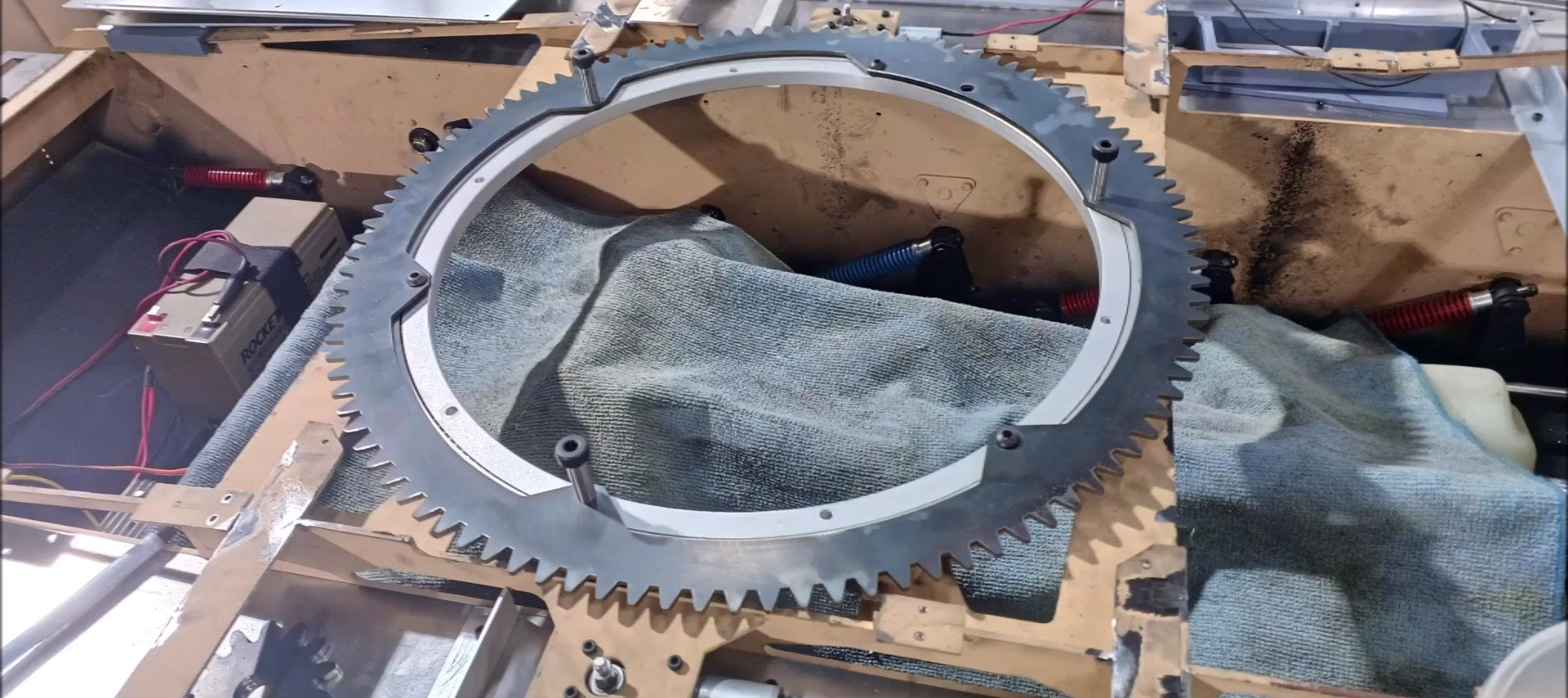
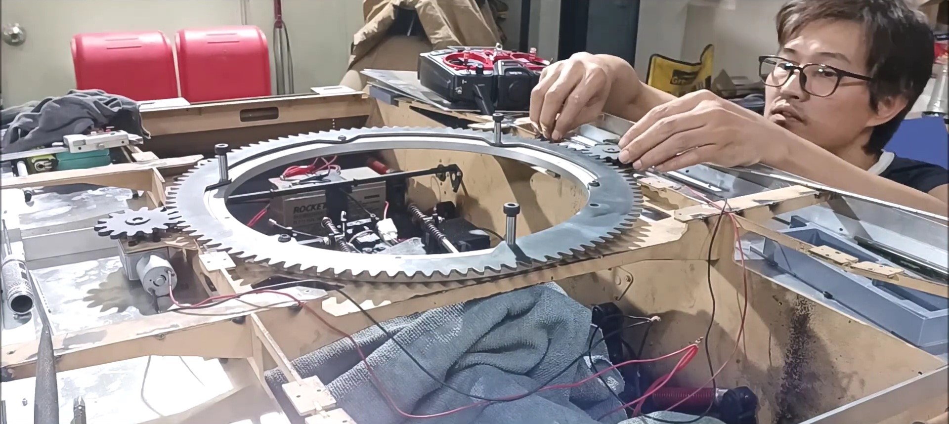
Bolt the turret outer wheel gear to the LAZY SUSAN turntable fixed to the body.
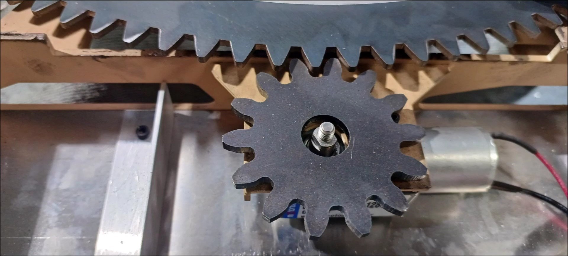
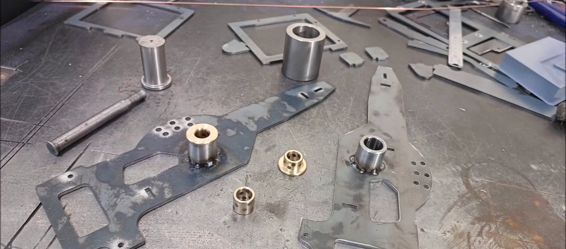
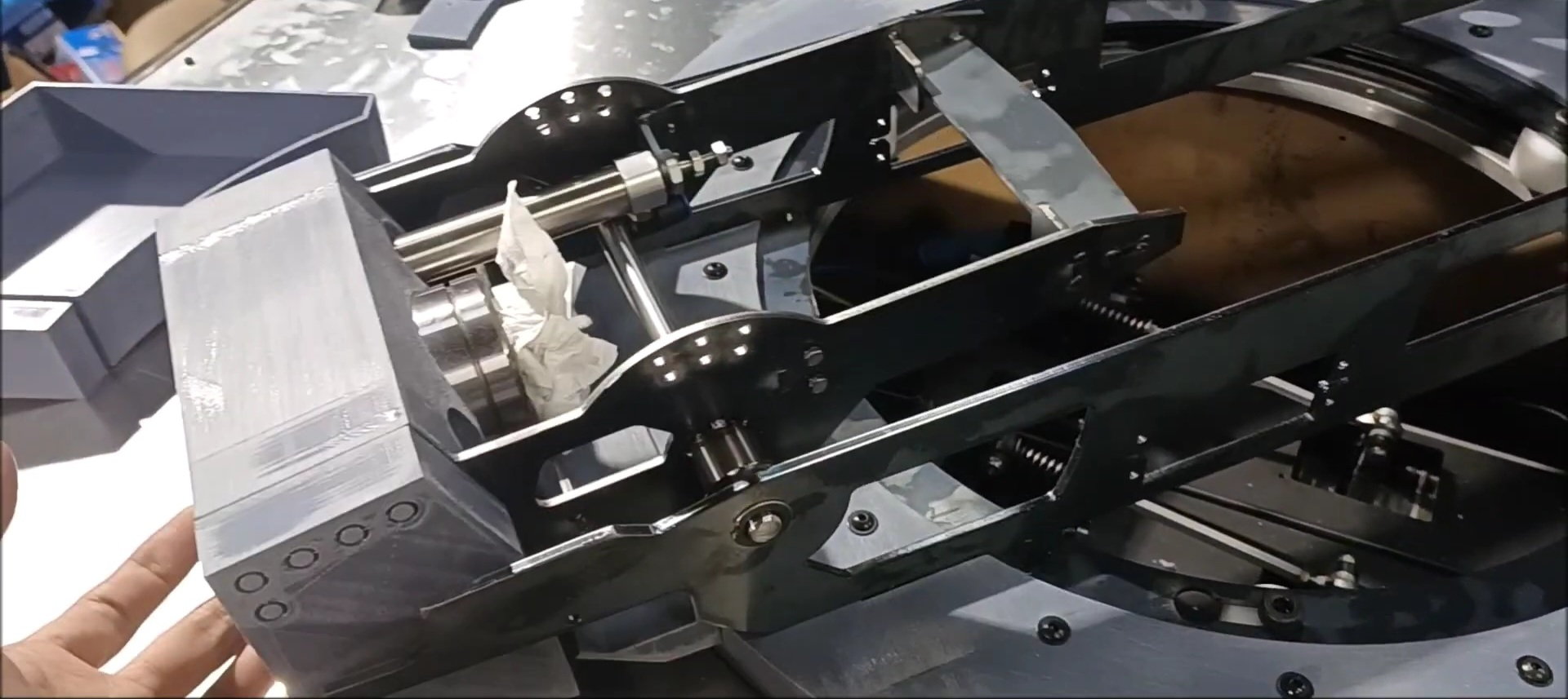
Check the position of the motor drive gear.
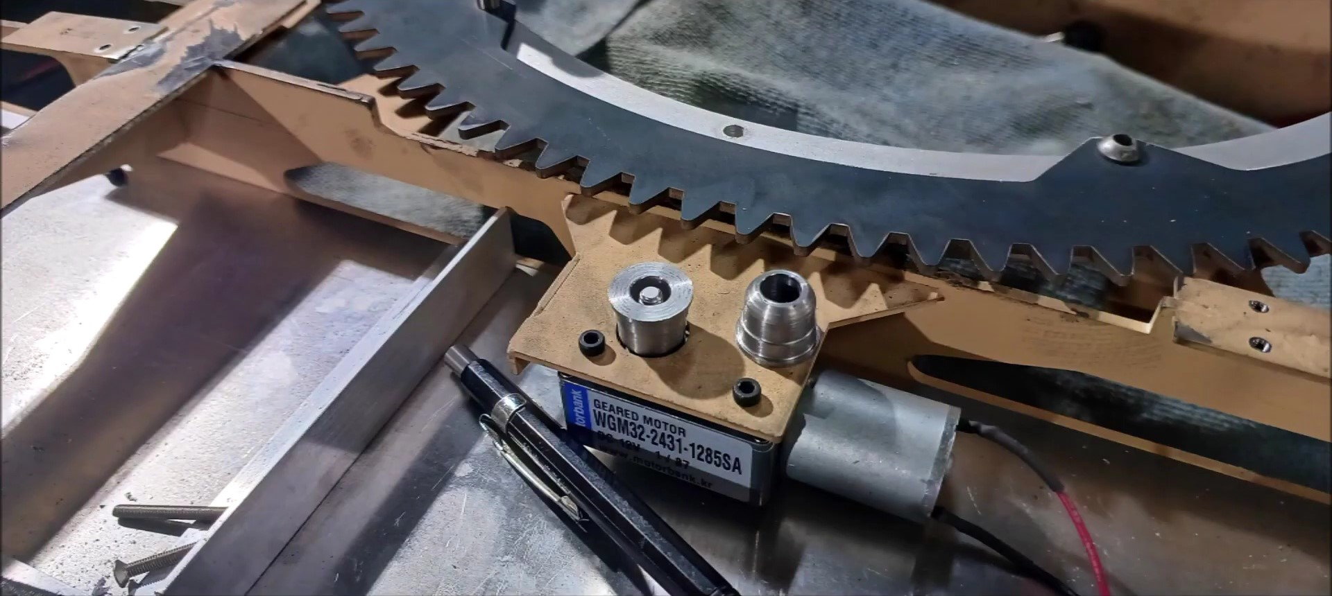
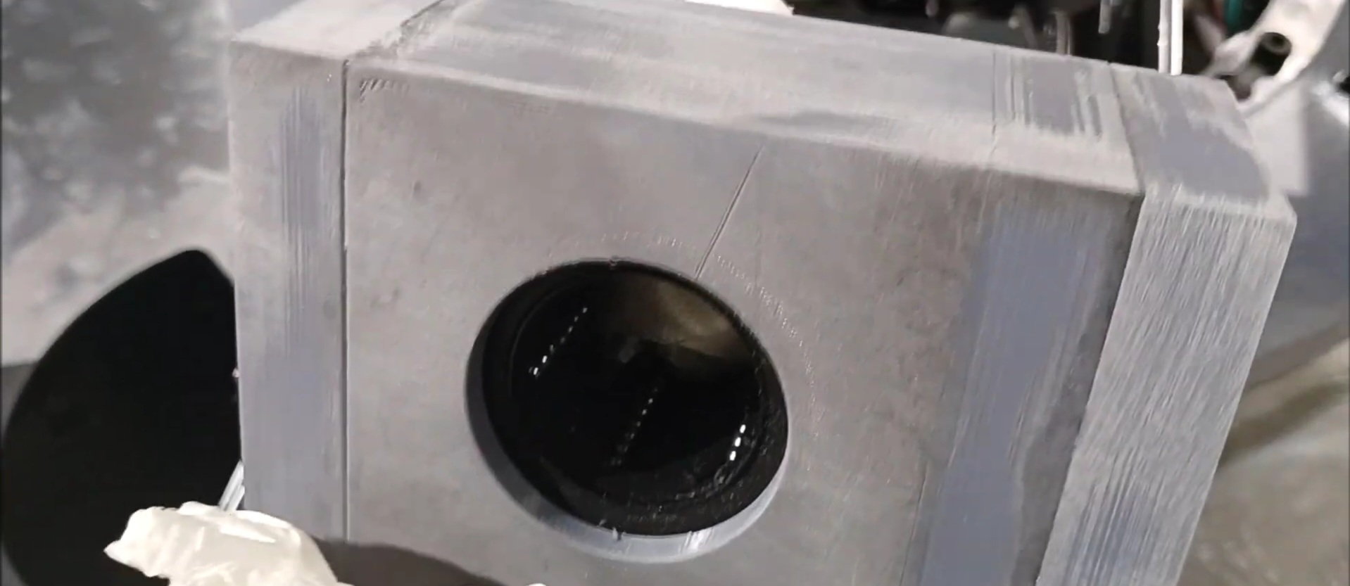
Consider fixing the hub of the drive gear and the motor shaft.
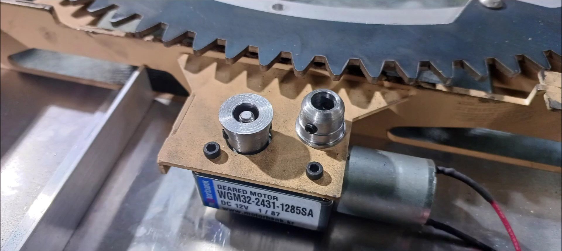
Consider fixing the hub of the drive gear and the motor shaft.
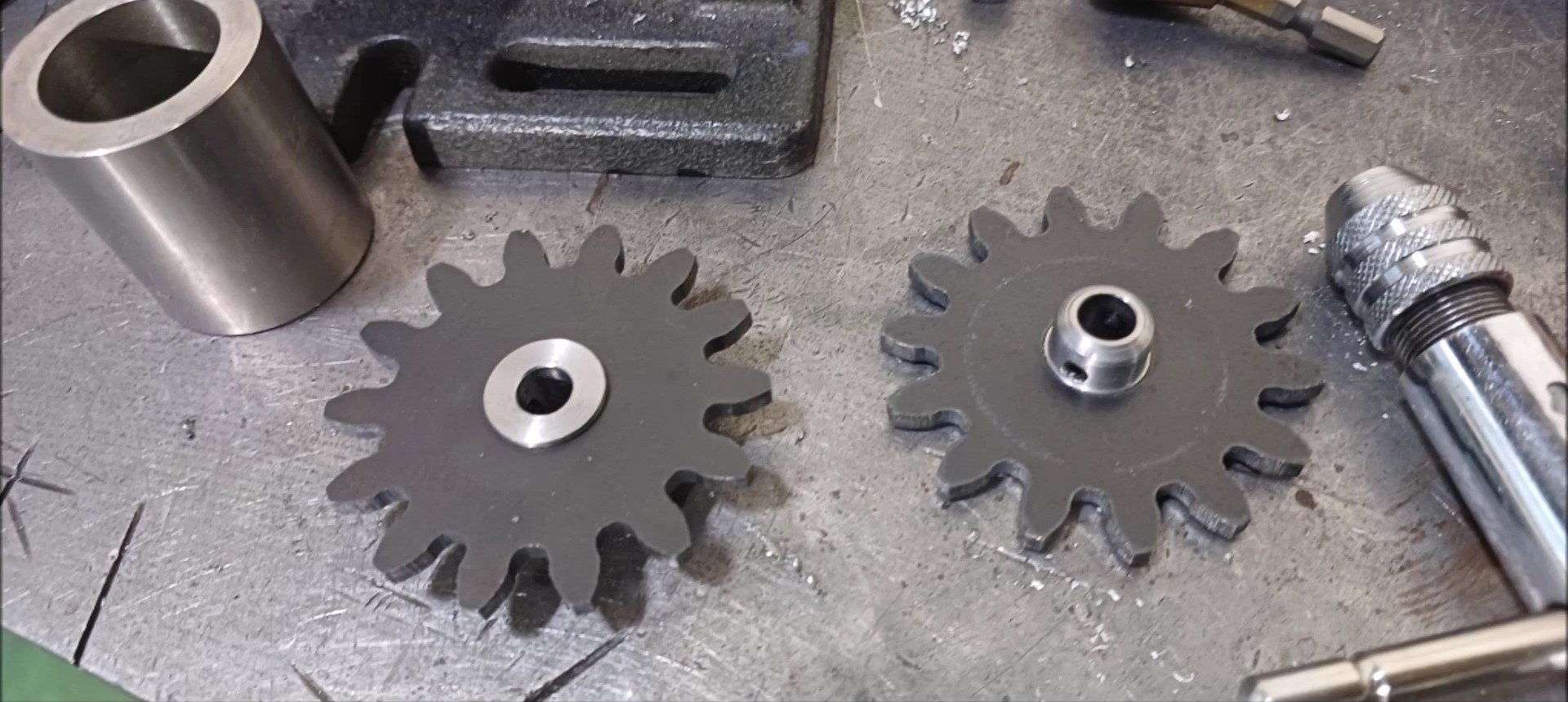
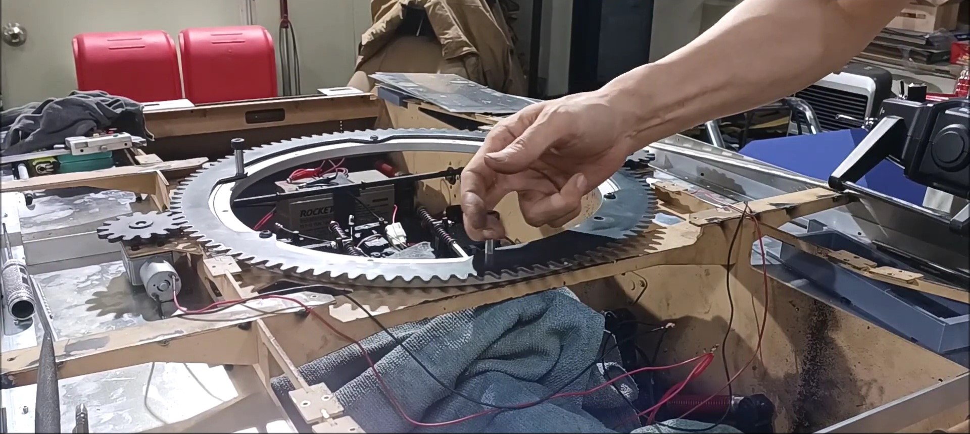
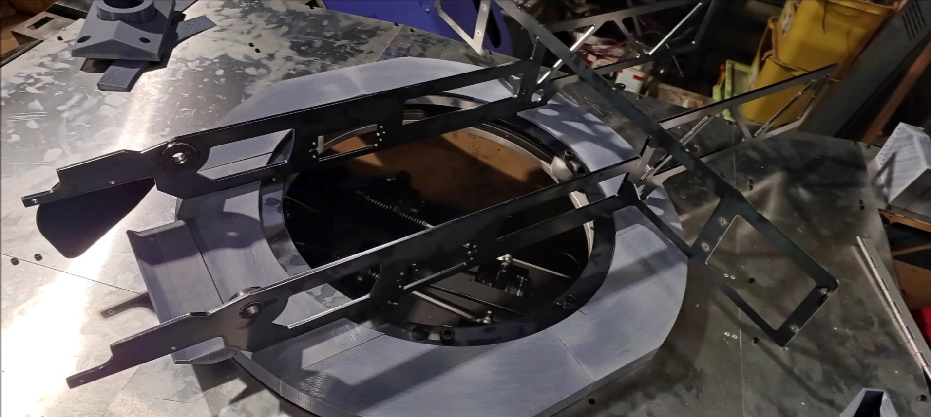
Position the drive gear and the shaft hub.
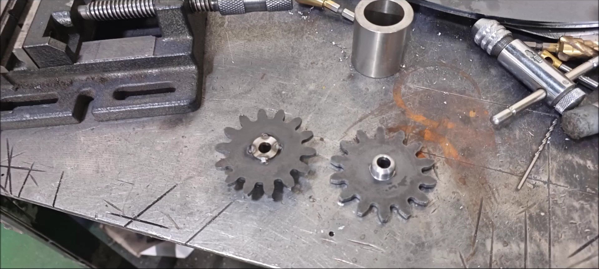
Weld the drive gear to the shaft hub.
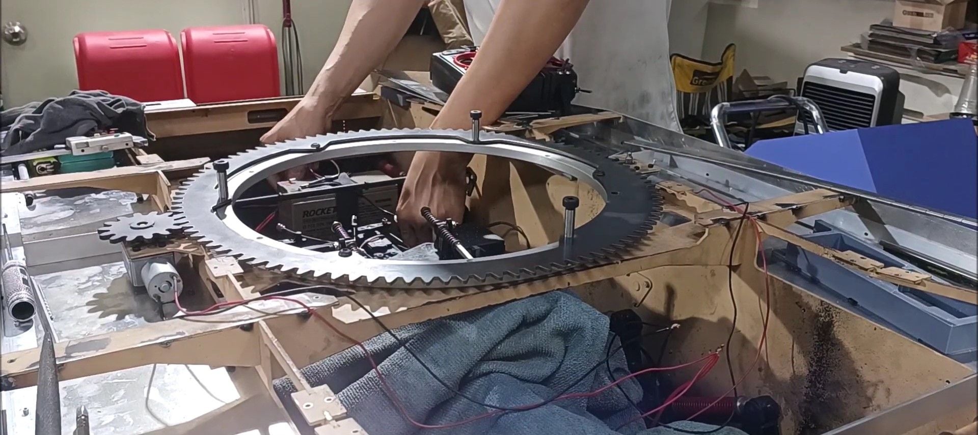
Test the turret gear. This operation uses an electric speed controller for RC cars.
First, one motor is operated to install the opposite motor gear at an appropriate position.
After the last outdoor test, we prepared the work of making the appearance of the tank.
Use 1.5mm aluminum angles and aluminum panels. Unlike the main structural materials that use steel, the materials that make up the appearance due to the limit of weight are made of aluminum
First, secure the aluminum angles to the left and right sides to match the design length.
The aluminum angle was fixed with a bolt.
Prepare the caterpillar upper plate to be connected to the angle.
The connection between the caterpillar upper plate and one angle was fixed using a rivet.
Fix the upper plate of the caterpillar to the left and right sides of the tank body.
Fix the upper plate of the caterpillar to the left and right sides of the tank body.
Add a 3D-printed structure to the caterpillar upper plate fixing. Secure the side plate here. Fix with screws.
Add a 3D-printed structure to the caterpillar upper plate fixing. Secure the side plate here. Fix with screws.
Install an engine exhaust port at the rear of the left upper plate and a plate with an inspection hole at the upper plate.
Make a temporary fix on the left side of the panel on the right caterpillar top with a vice plier and fix it with a bolt.
The left panel size of the right caterpillar top panel is different from the last version, as in the real K2, and the main power control panel will be installed at the rear right.
The size of the left panel on the right caterpillar top is different from the previous version in the left and right as in the real K2. The right side is thicker than the left back furniture.
Secure the motor to the left and right to control the turret. These are geared motors.
This version is an outer wheel turret, so I'll try to position it first.
First, fix the body and LAZY SUSAN turntable ring first.
Bolt the turret outer wheel gear to the LAZY SUSAN turntable fixed to the body.
Check the position of the motor drive gear.
Consider fixing the hub of the drive gear and the motor shaft.
Consider fixing the hub of the drive gear and the motor shaft.
Position the drive gear and the shaft hub.
Weld the drive gear to the shaft hub.
Test the turret gear. This operation uses an electric speed controller for RC cars.
First, one motor is operated to install the opposite motor gear at an appropriate position.
Last edited by PE YOUNG; 09-23-2023 at 06:36 PM.
09-23-2023, 06:20 PM
#132
Thread Starter
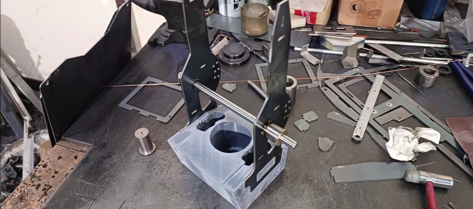
Secure the opposite motor gear to the motor shaft.
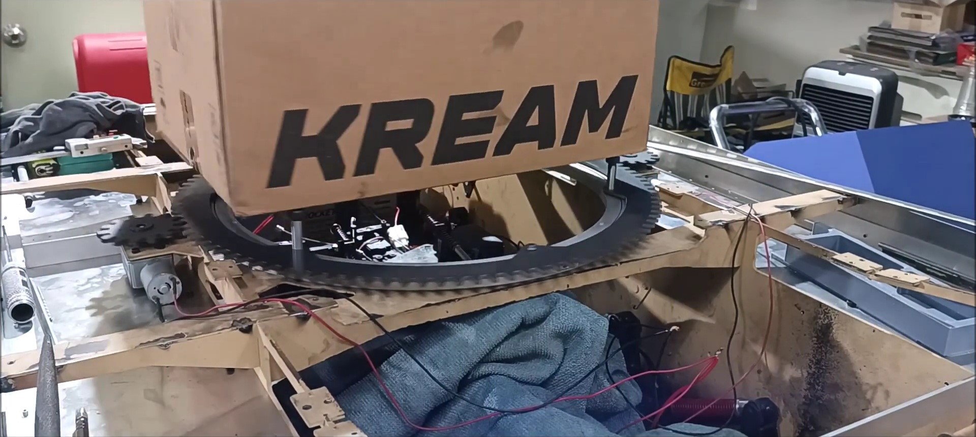
Position the box for rotation test (see video)
Motor performance is also checked by applying resistance to rotational motion.
Secure the turret in the neutral position. The turret does not rotate freely due to the influence of the geared motor.
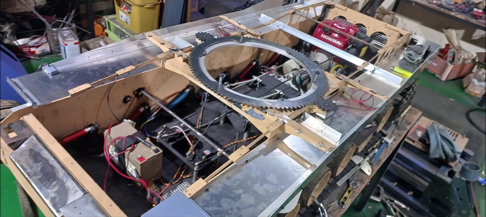
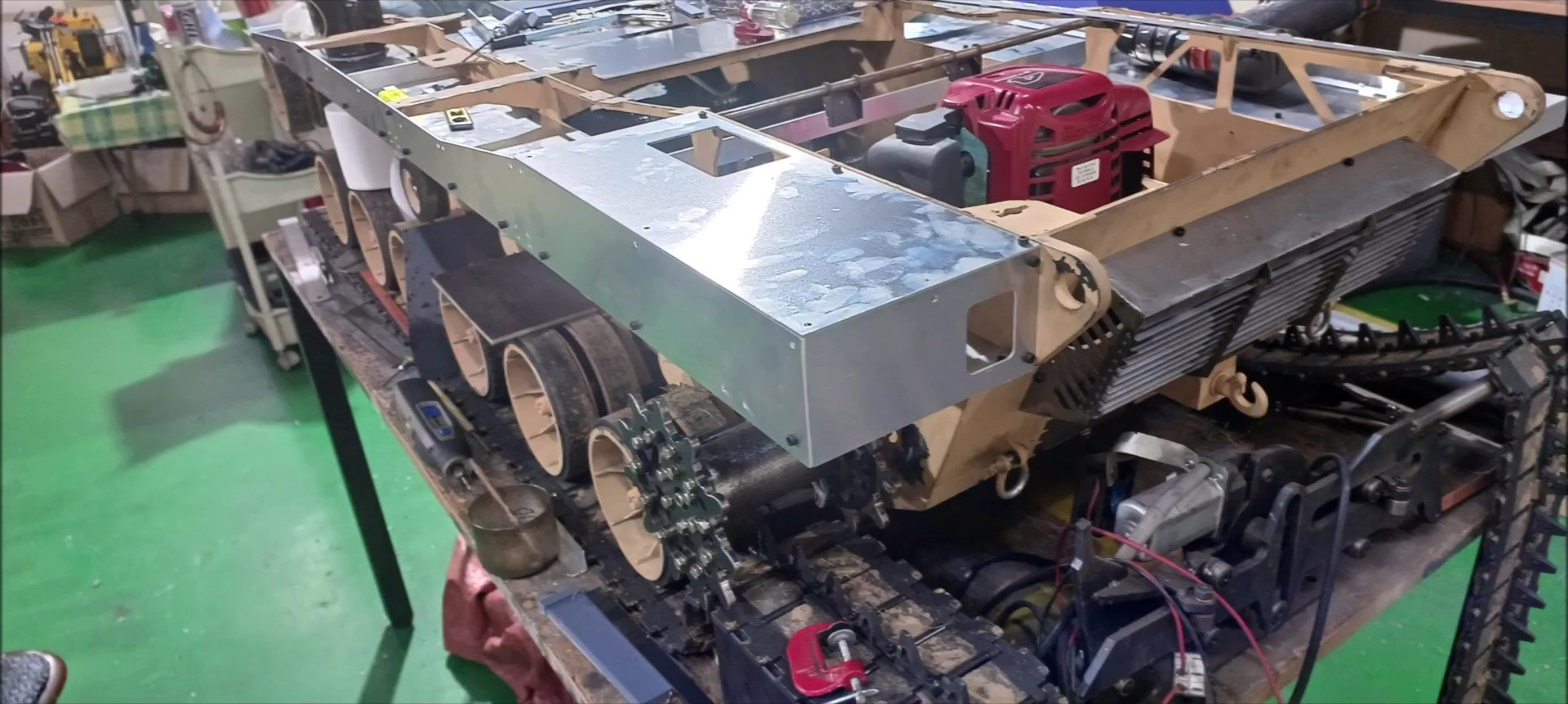
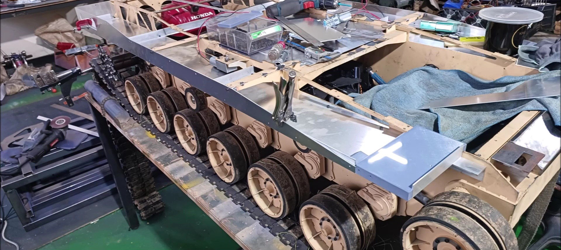
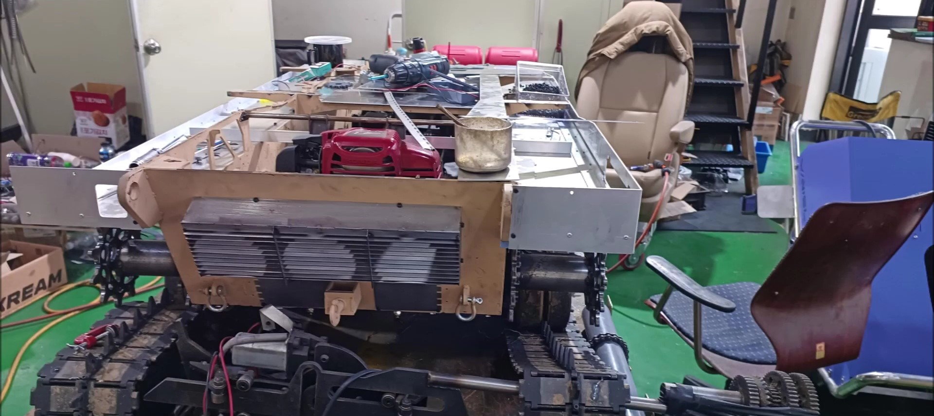
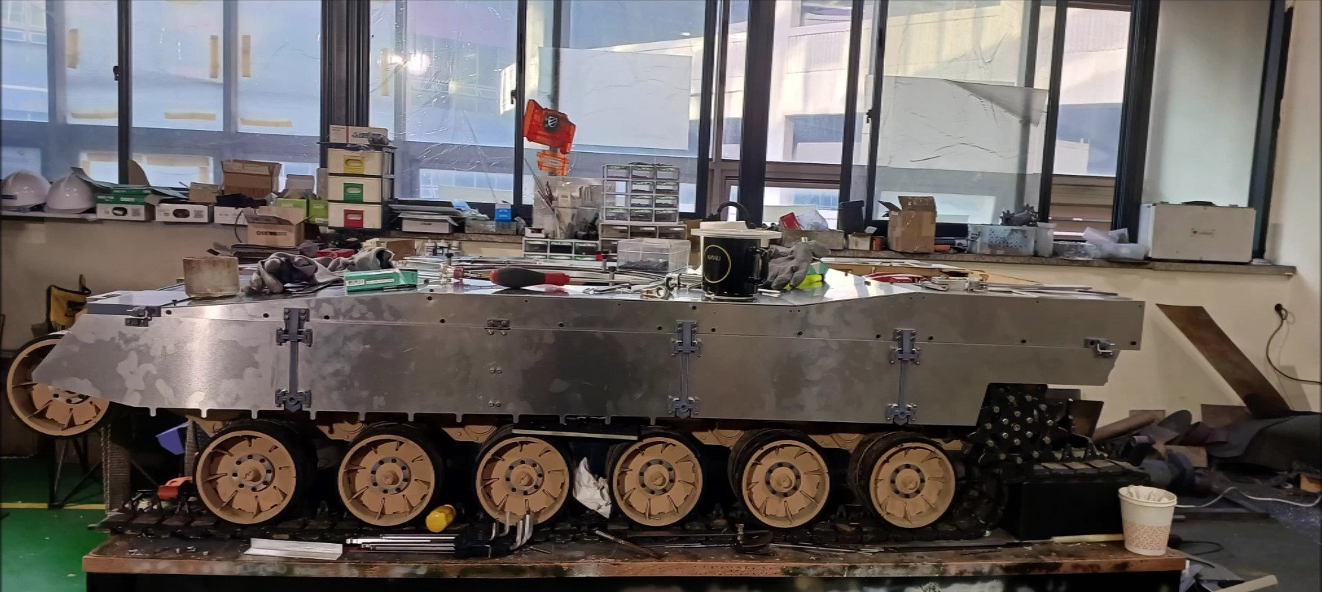
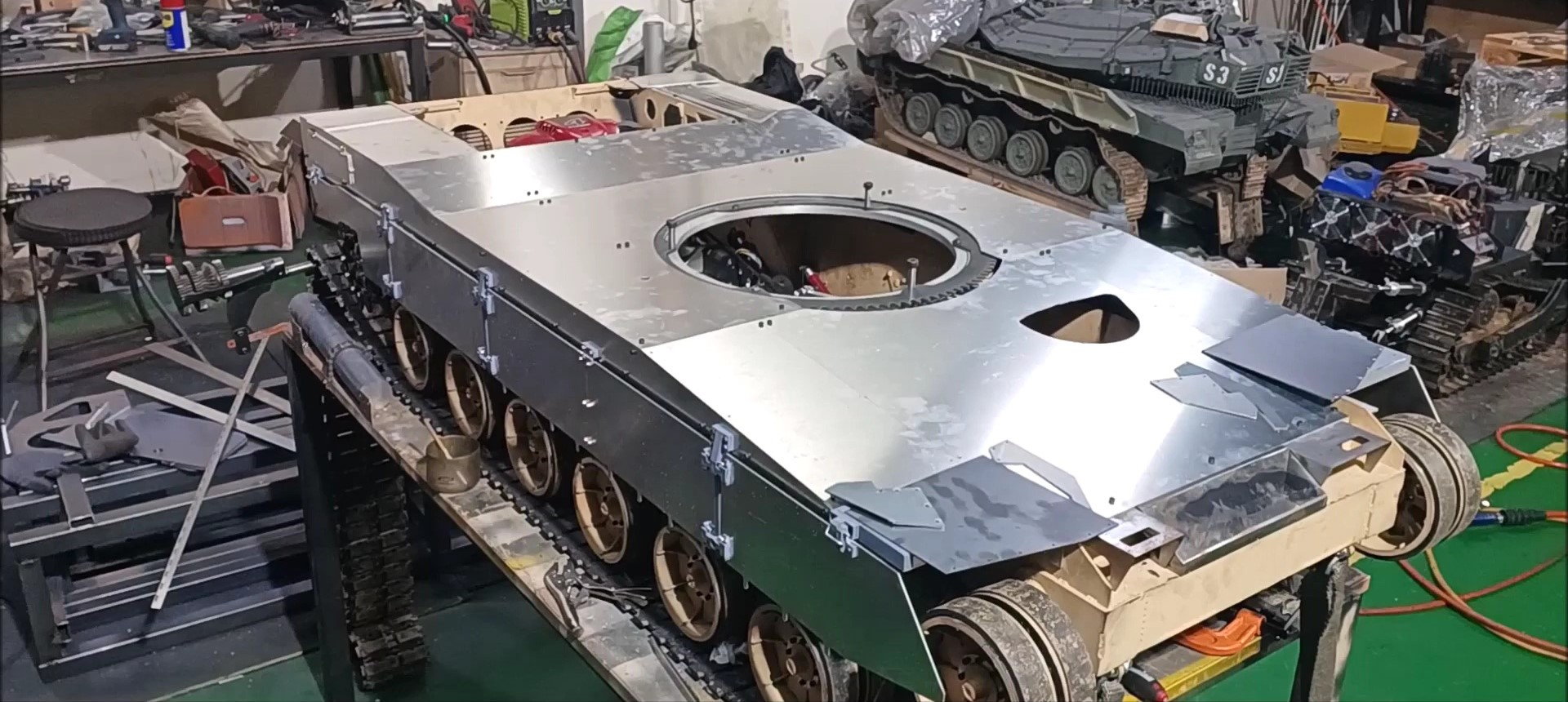
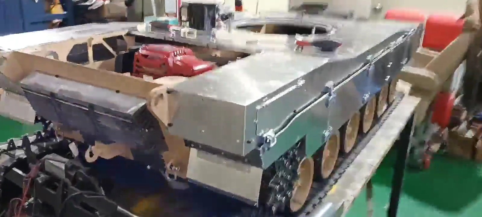
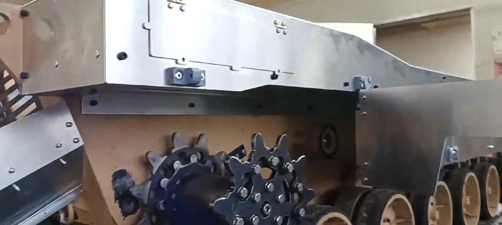
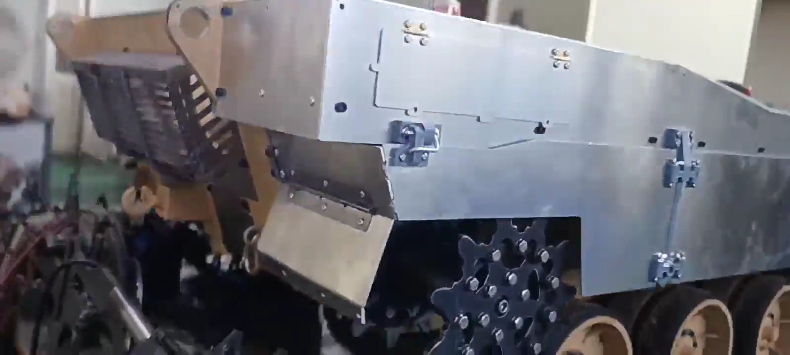
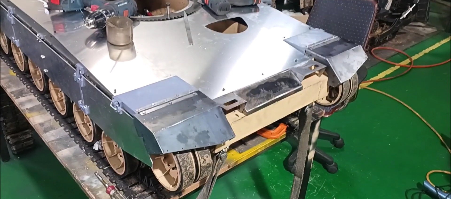
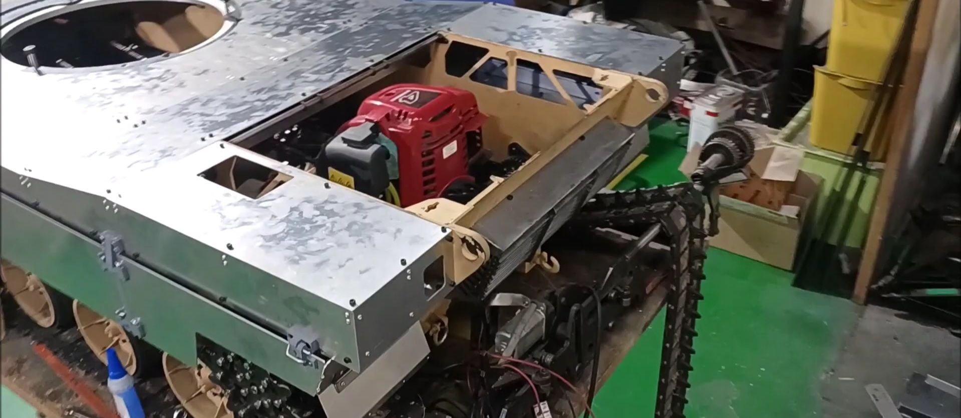
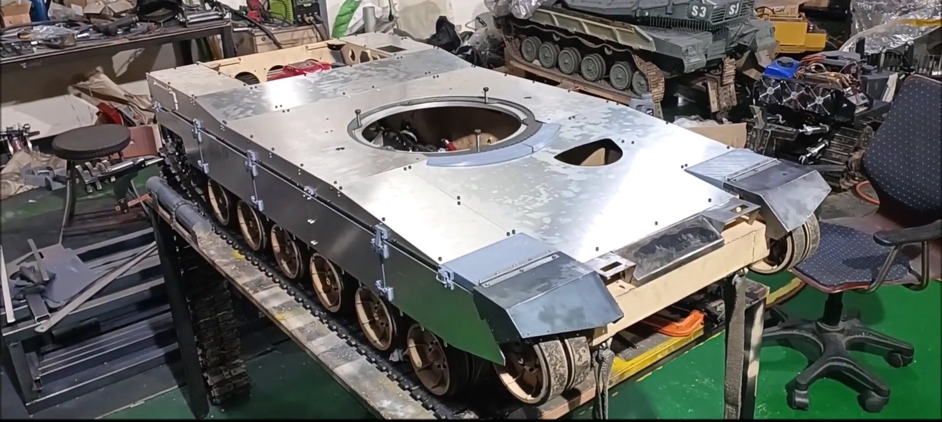
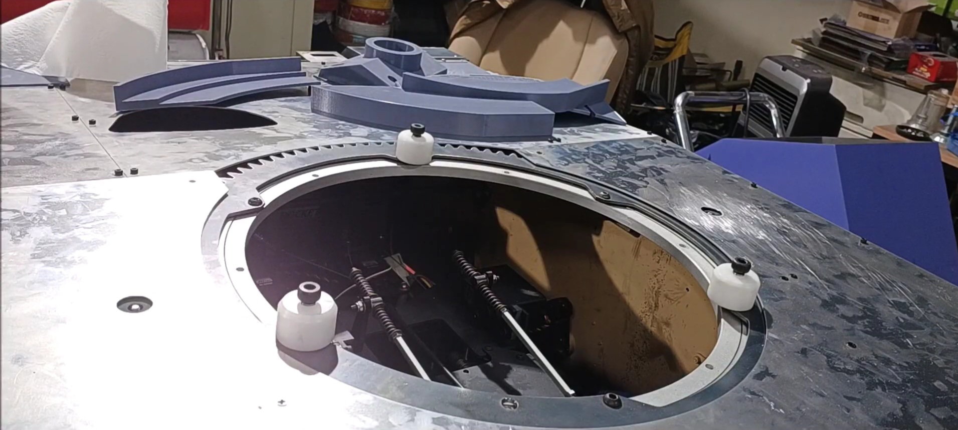
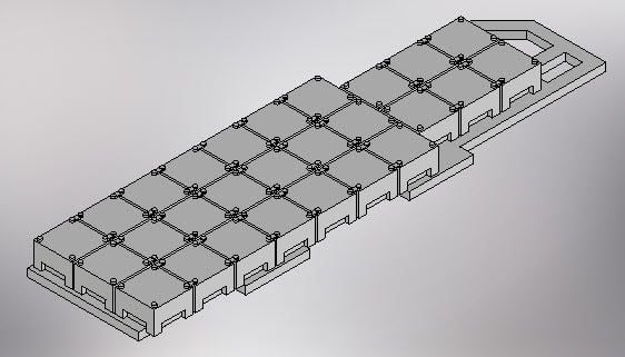
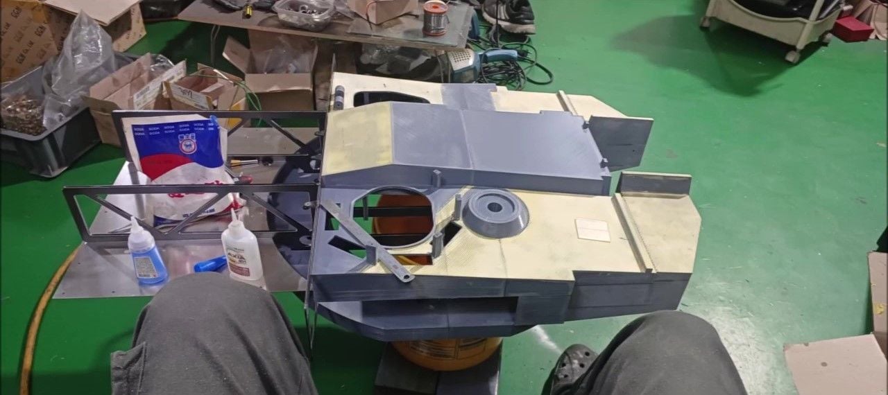
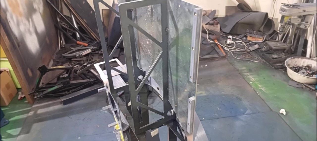
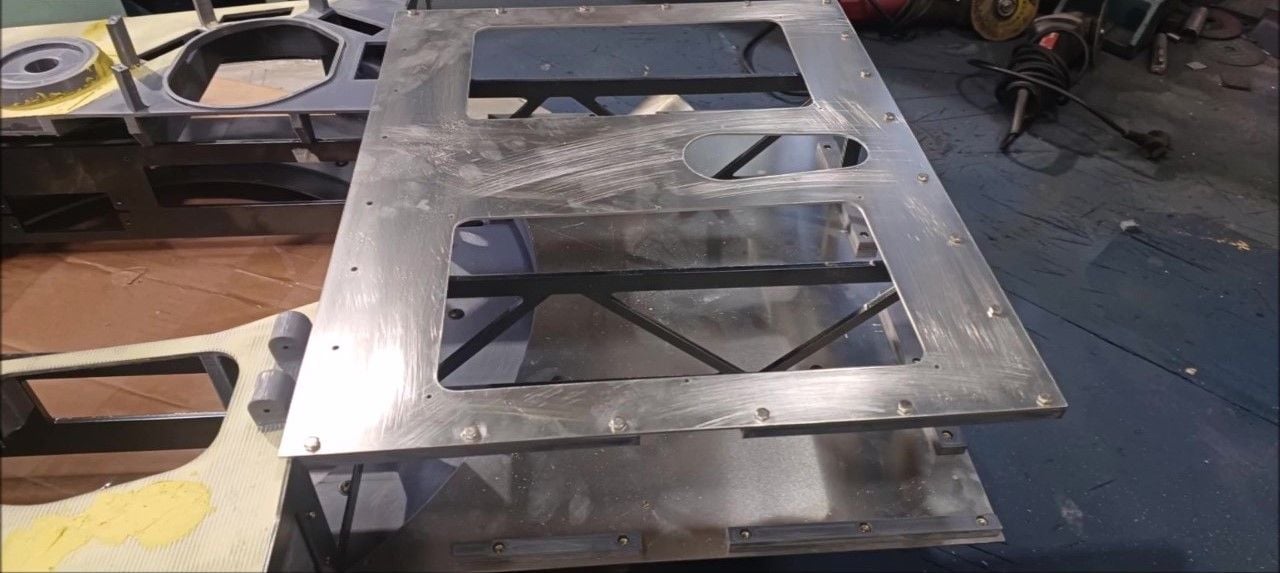
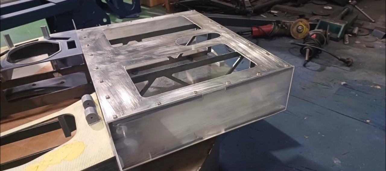
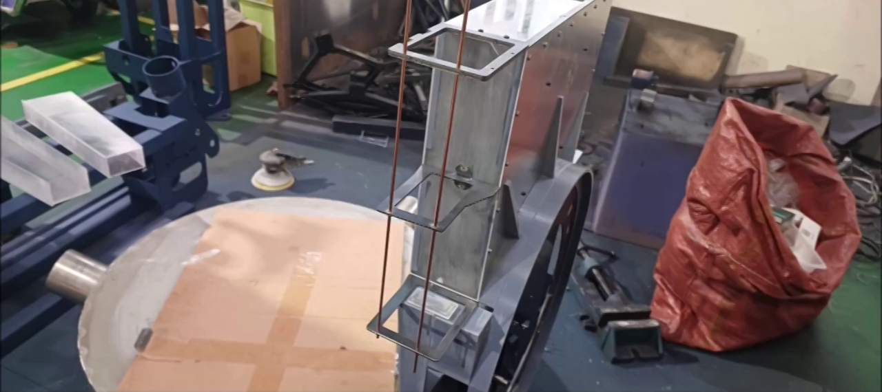
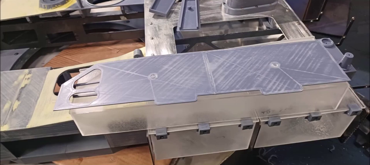
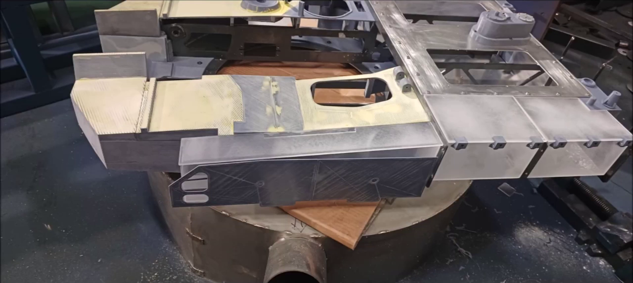
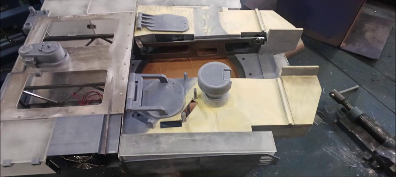
After the turret test, assemble the upper hull.
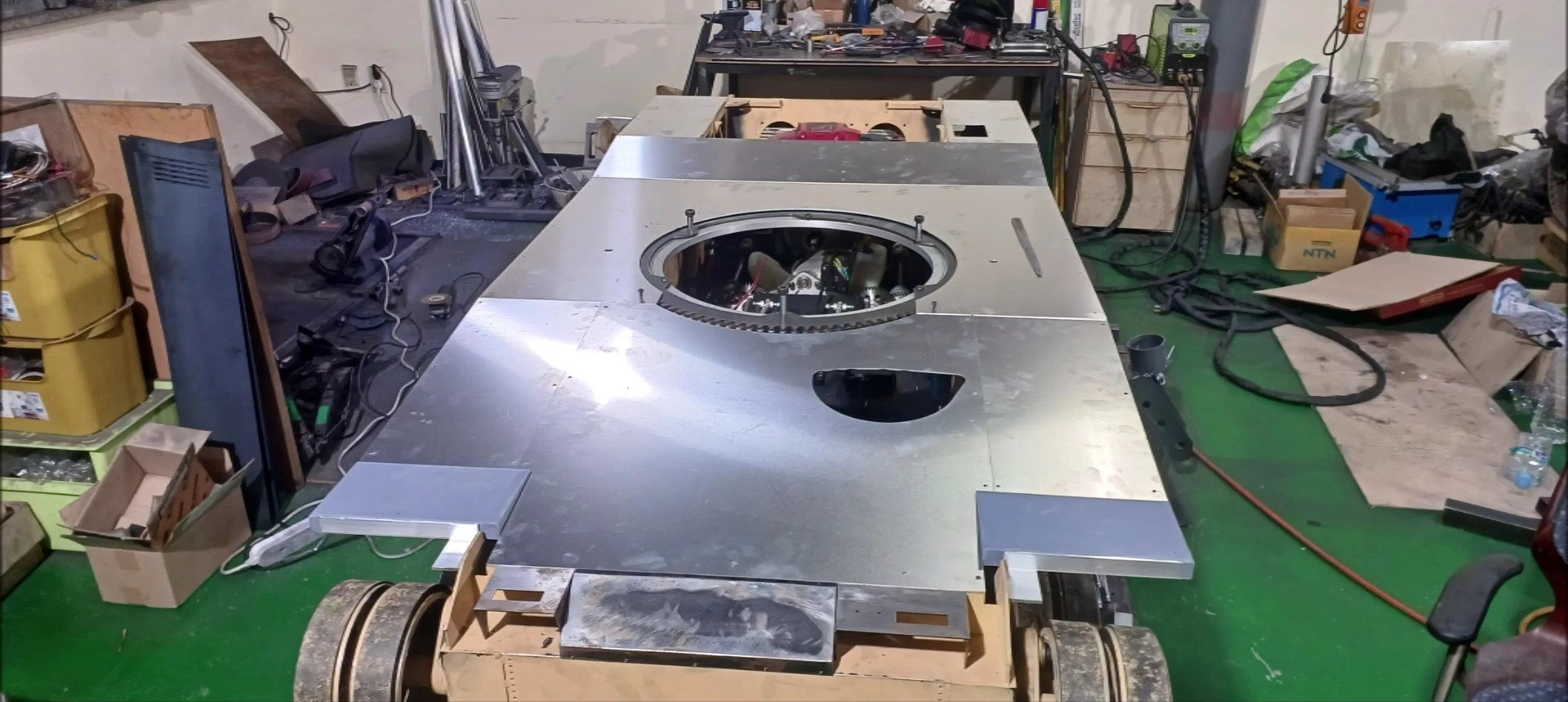
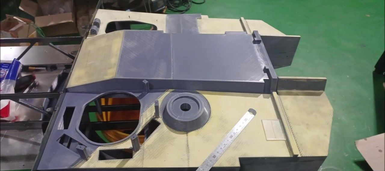
Complete the upper hull assembly and inspect from all directions.
Complete the upper hull assembly and inspect from all directions.
Complete the upper hull assembly and inspect from all directions.
Complete the upper hull assembly and inspect from all directions.
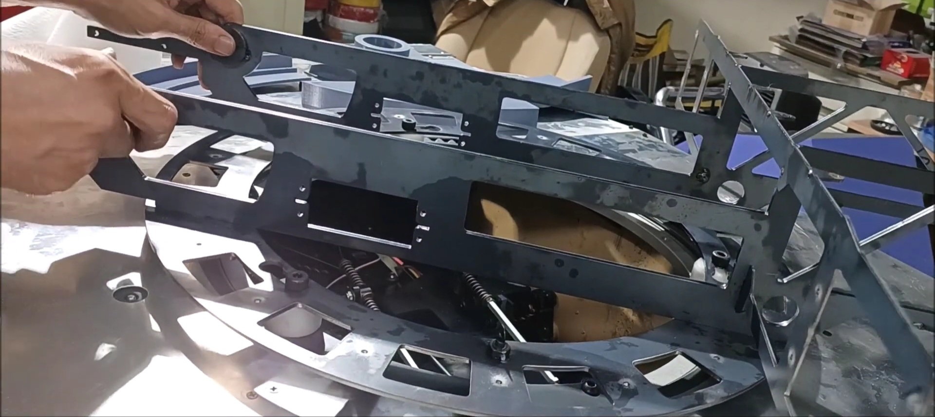
When changing the design, check the bolt hole on the body that is missing from reflecting the change. Do separate drilling work later.
When changing the design, check the bolt hole on the body that is missing from reflecting the change. Do separate drilling work later.
When changing the design, check the bolt hole on the body that is missing from reflecting the change. Do separate drilling work later.
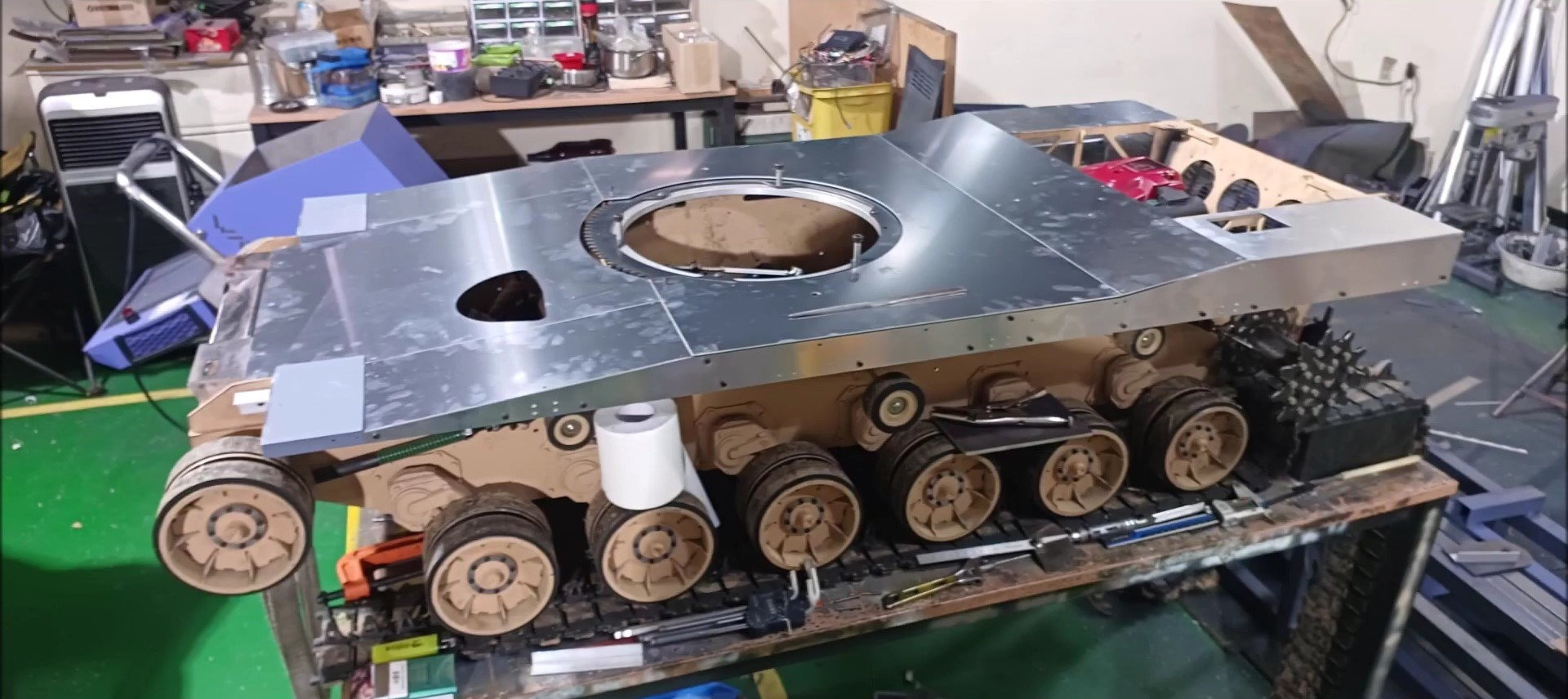
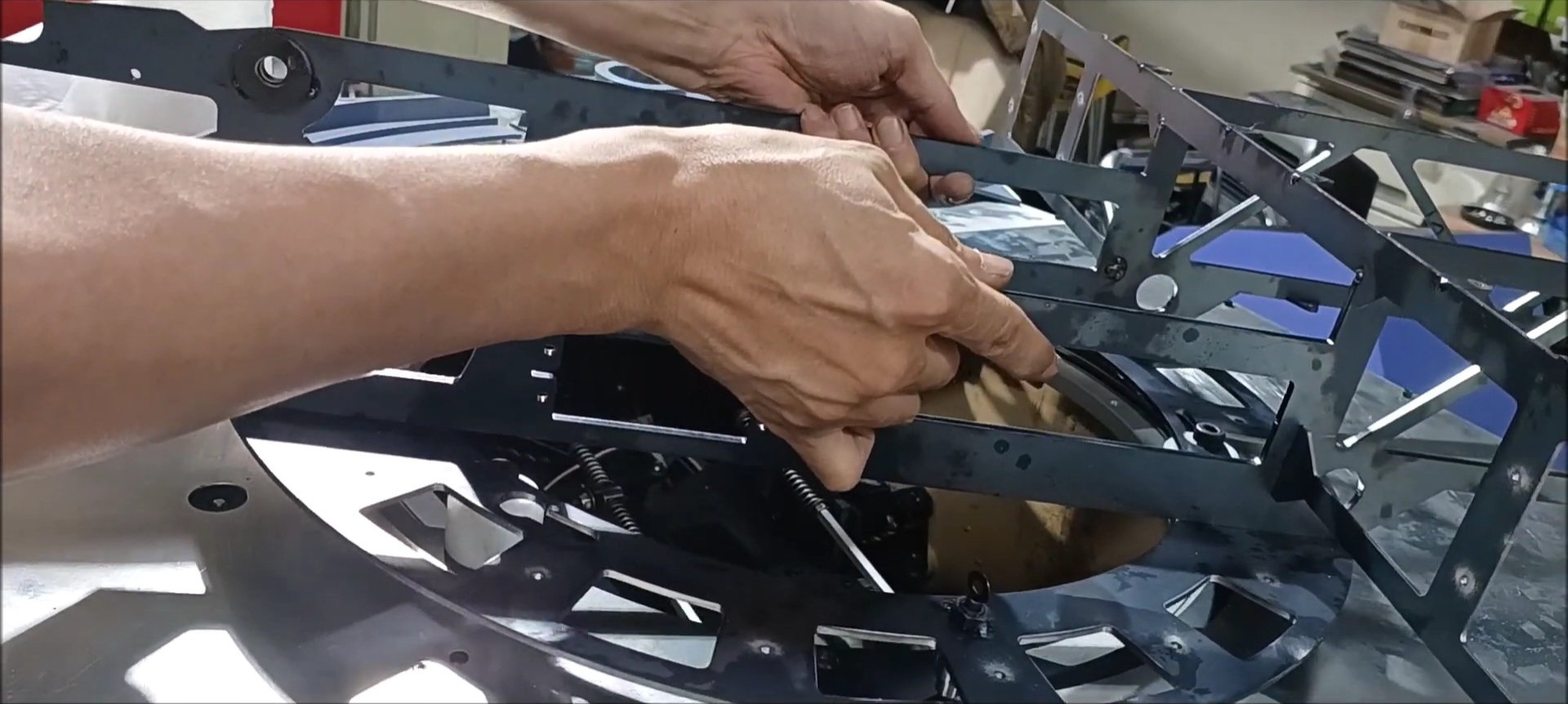
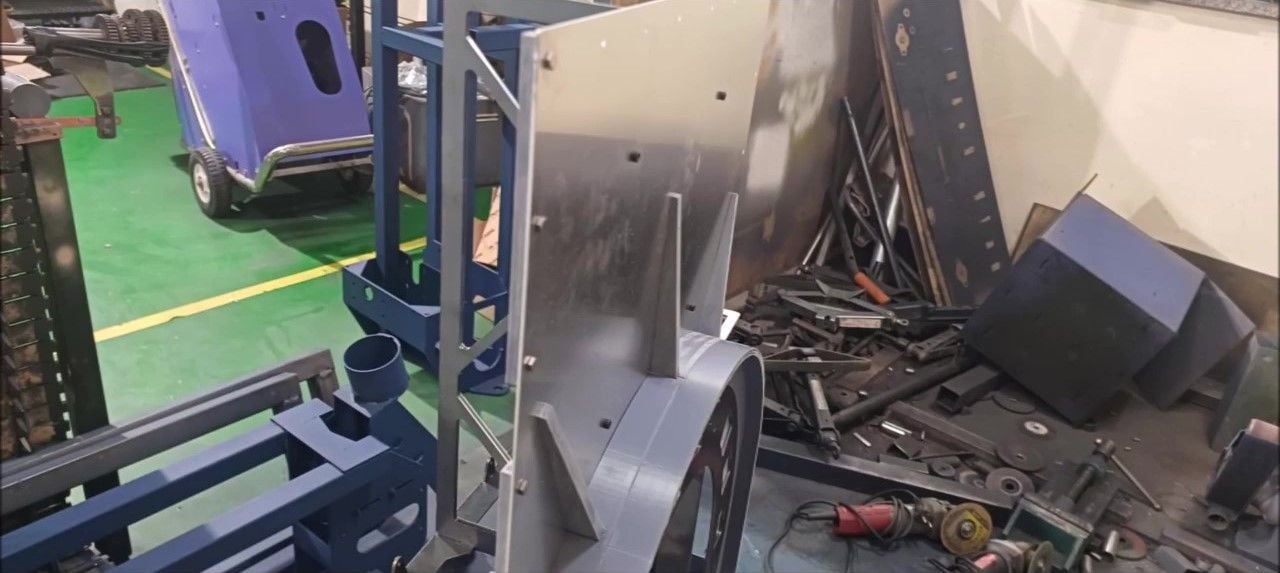
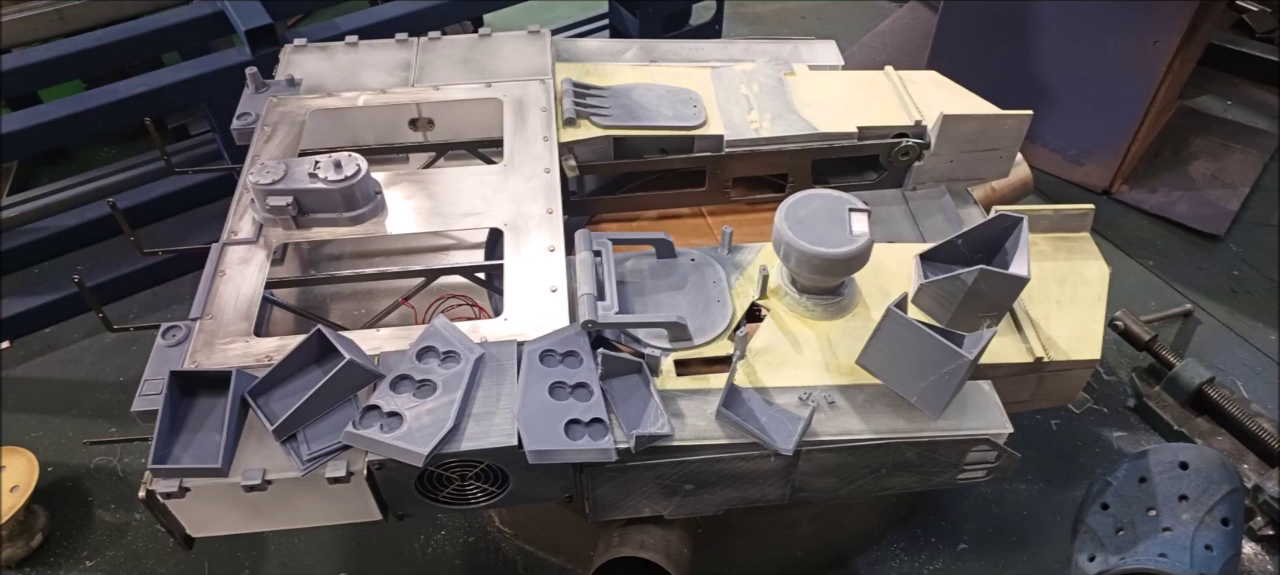
It is easy to install if the upper hull of the tank body is made into a single plate, but it is divided into a number of plates to facilitate accessibility for necessary detail lines and future vehicle inspections.
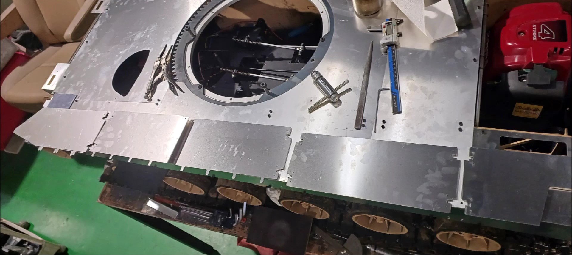
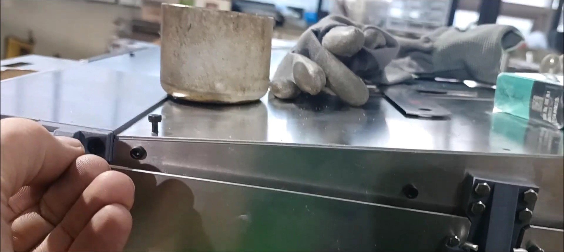
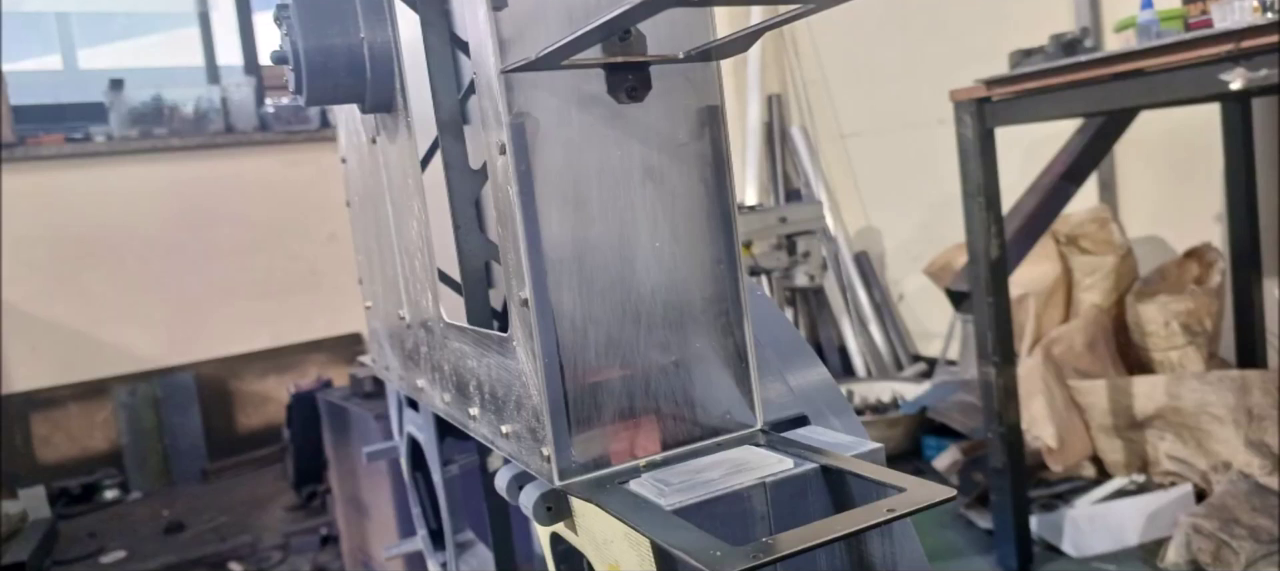
Prepare the side skirt work.
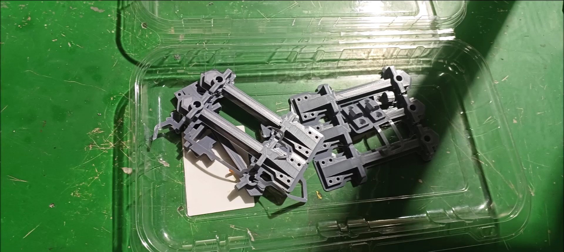
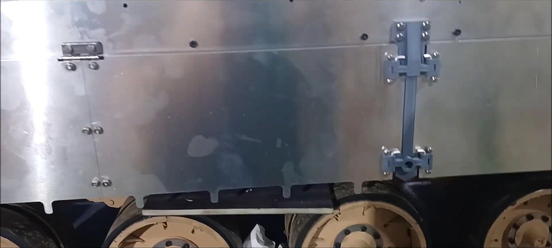
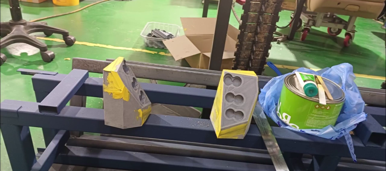
Print the side skirt fixing parts to the 3D printer.
Bolt the side skirt fixing part to the side of the K2 tank body.
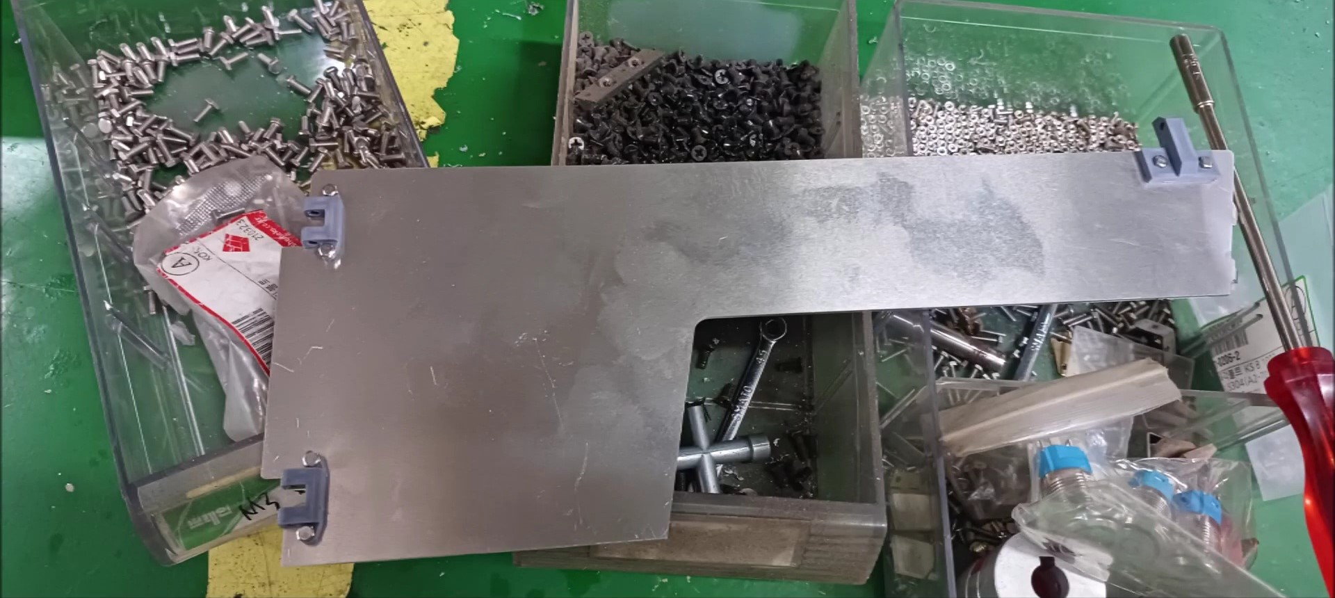
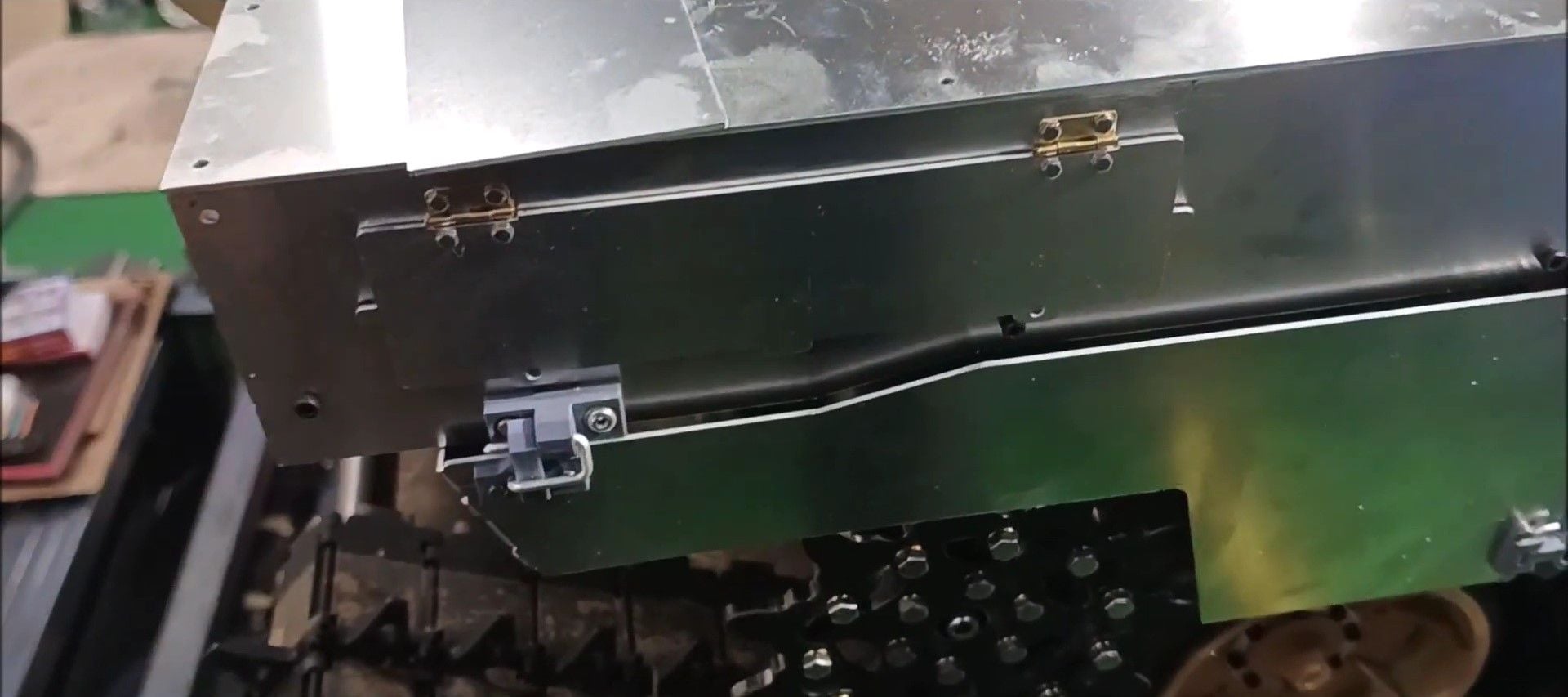
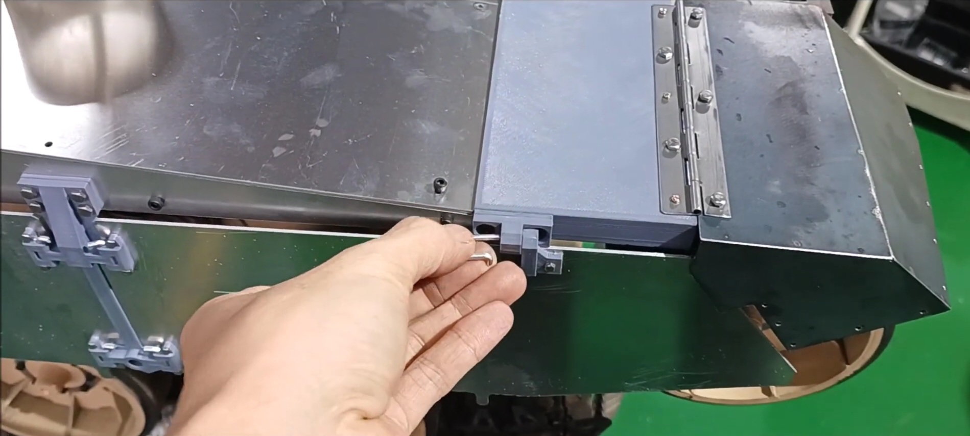
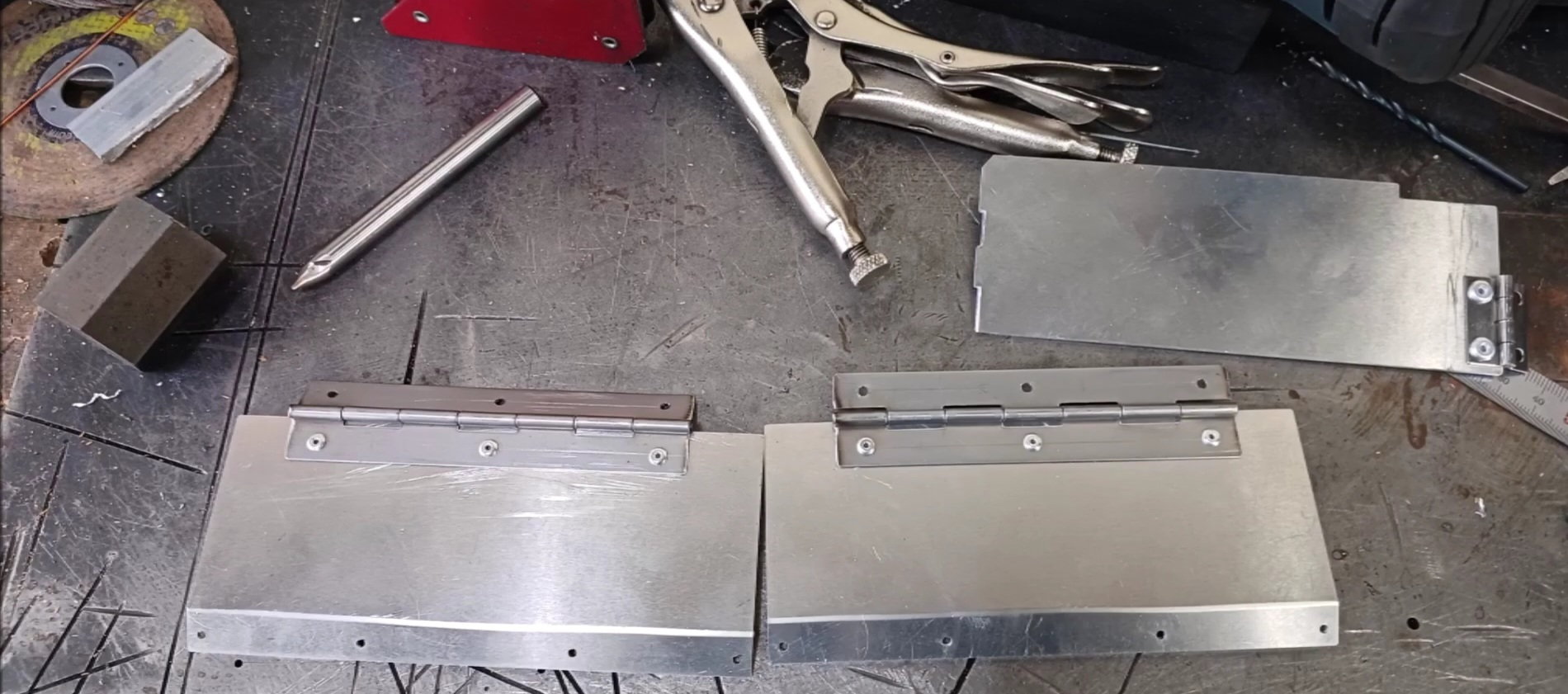
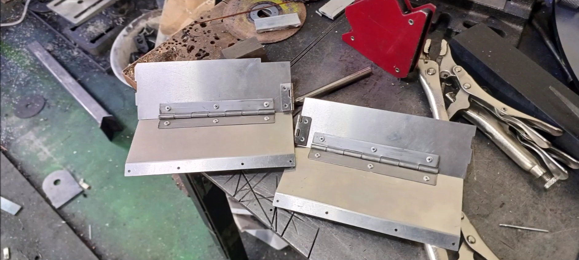
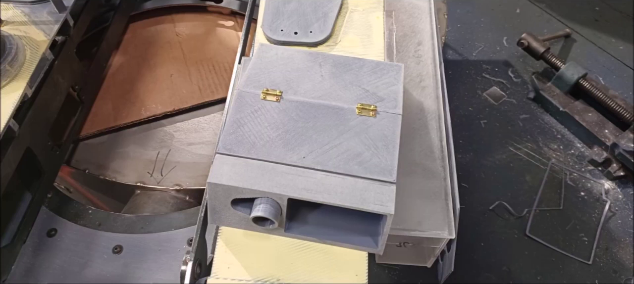
Install the securing hinge on the side skirt. These hinge parts are also printed out with a 3D printer and secured with bolts.
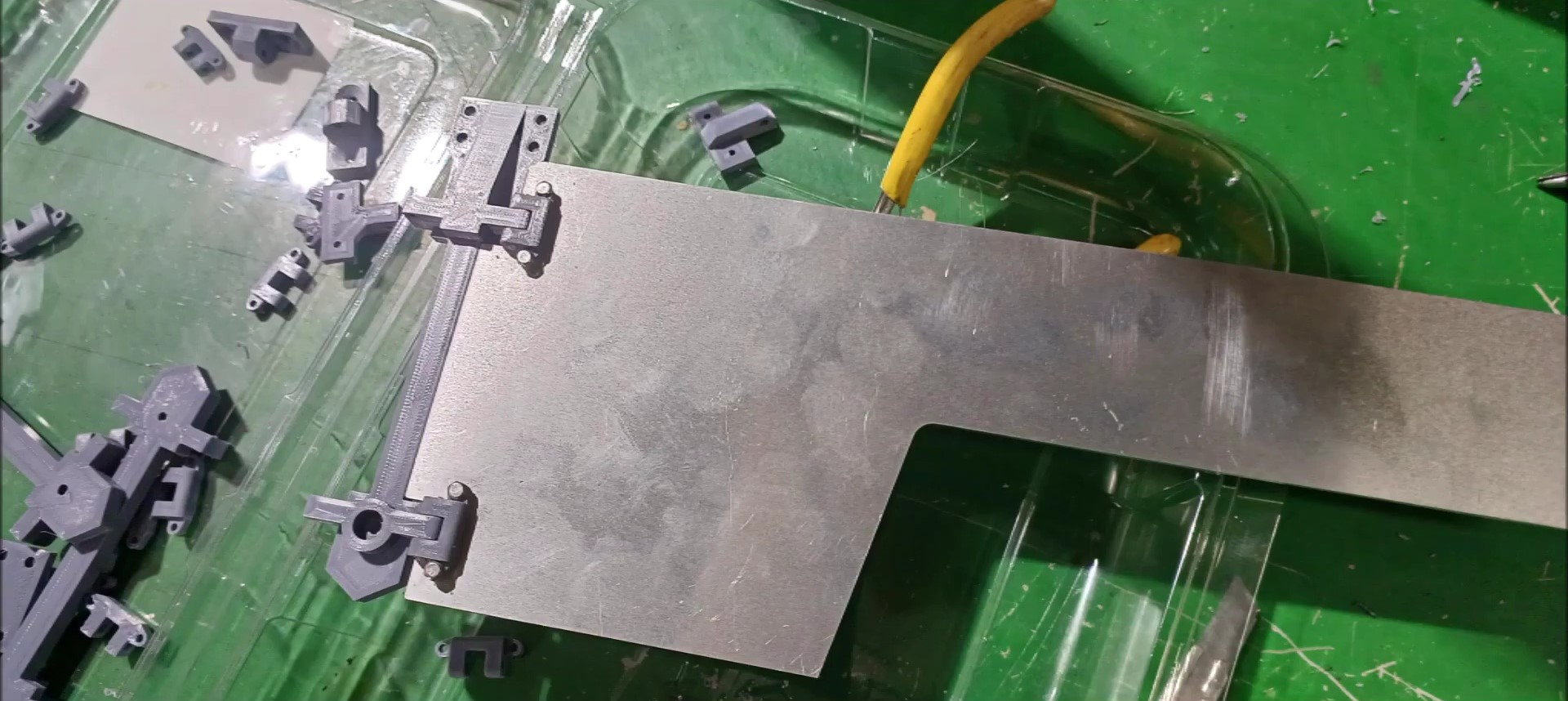
Install the securing hinge on the side skirt. If necessary, check the fixture and location.

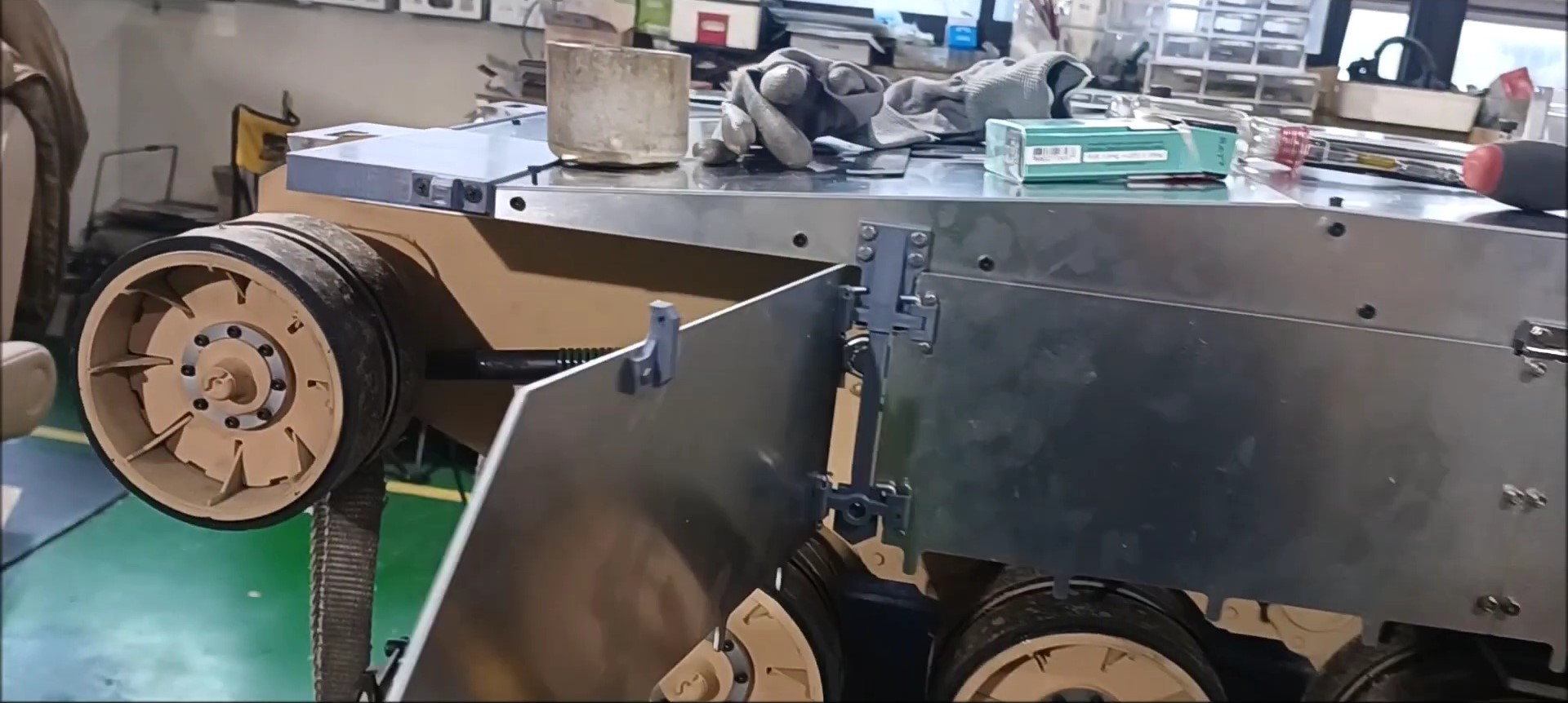
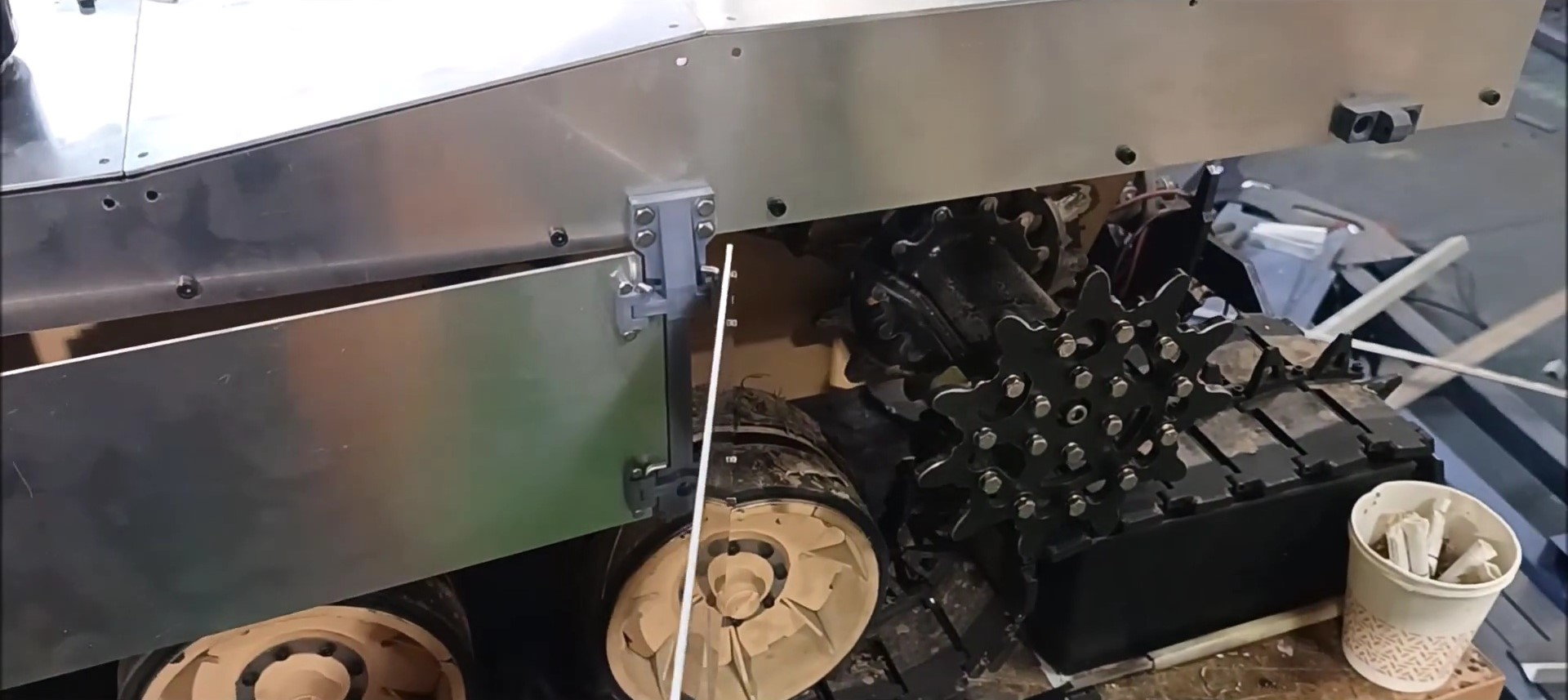
First, install the left side skirts.
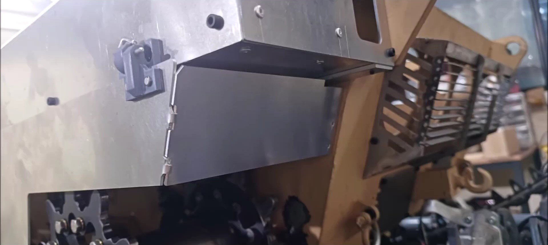
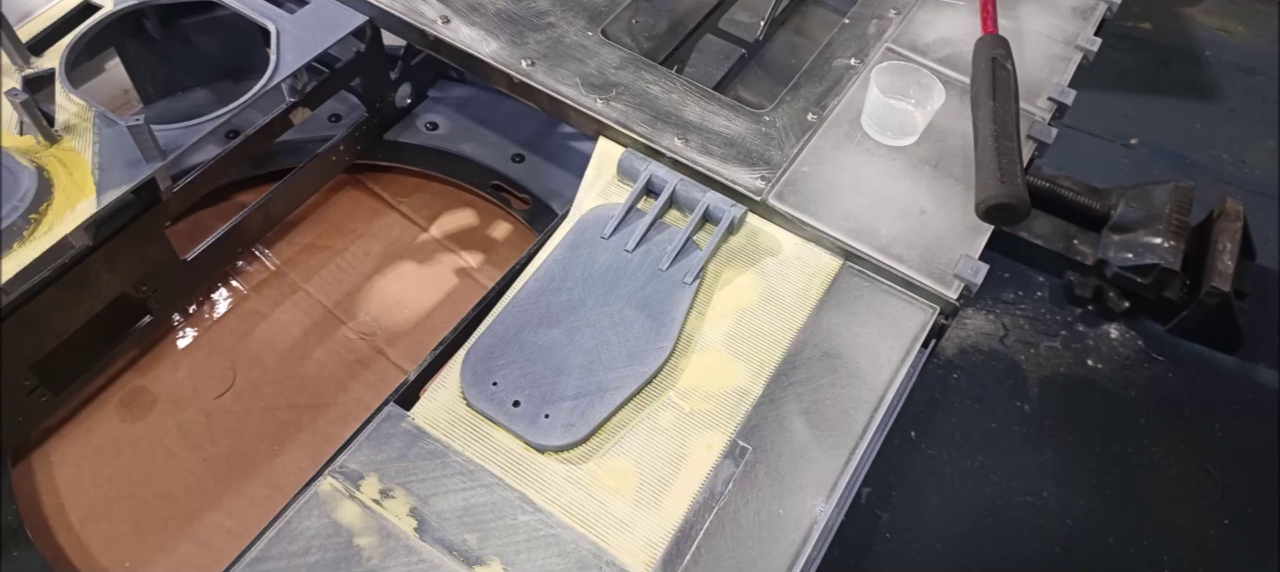
Check the position of the back mudrest to connect to the last rear side skirt.
The way the back of the mudrest is fixed and operated is similar to the real K2 unlike the previous version.
Left Side Skirt Installation Completed
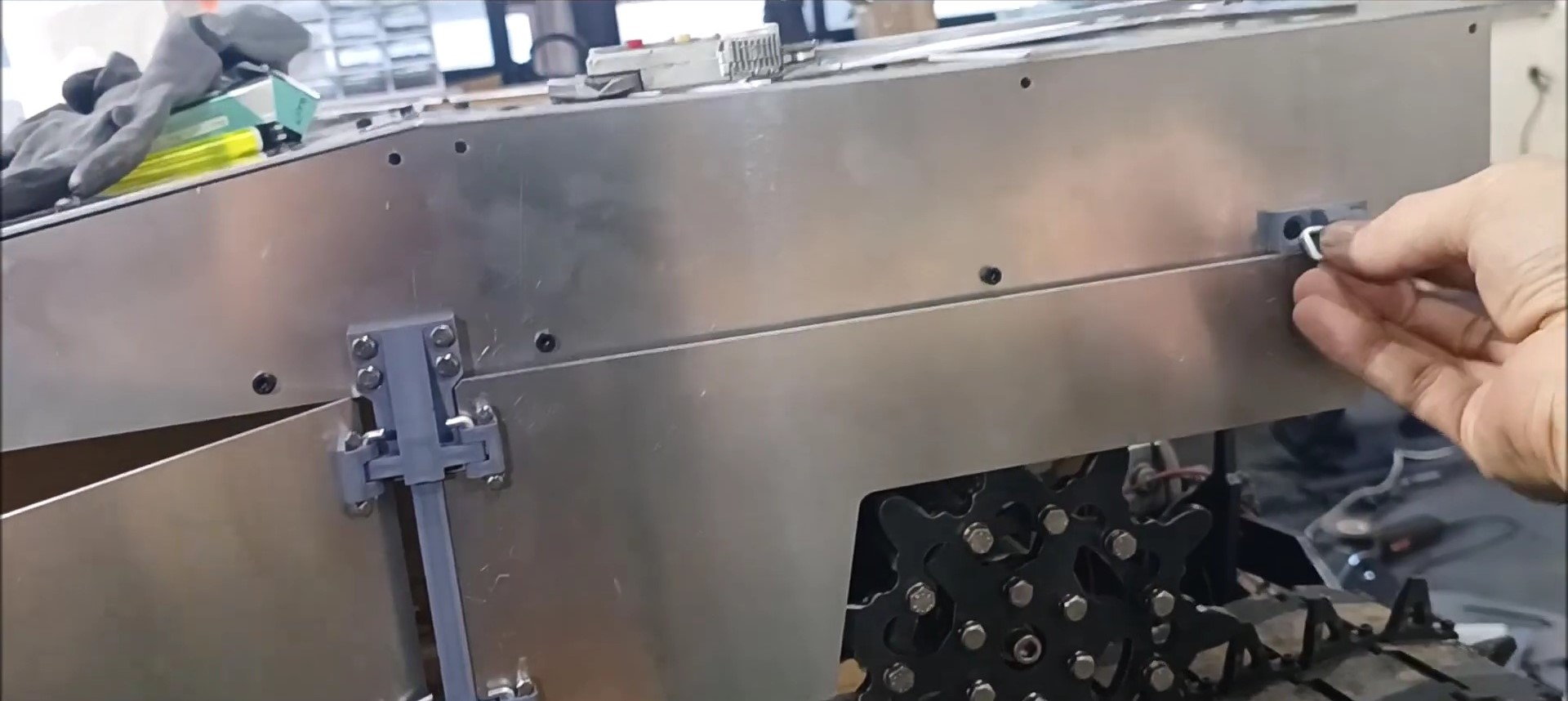
If the fixing pin is removed during use......
Open in a way that unfolds.
The 2nd and 3rd tier side skirts can be raised simultaneously when all fixing pins are removed.
09-23-2023, 06:31 PM
#133
Thread Starter
If the fixing pin is removed during use......
Open in a way that unfolds. If all pins are removed, the side skirt may also be removed.
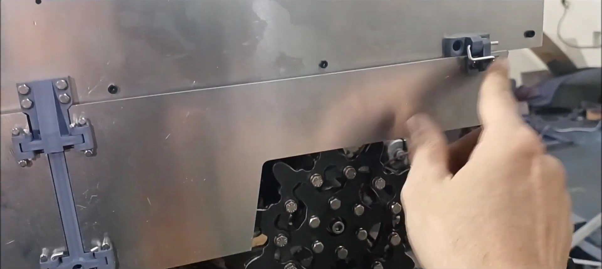
If the fixing pin on the last plate is removed, the last side skirt and mudrest can also be checked.
Right Side Skirt Installation Completed
Right Side Skirt Installation Completed
Check the location and method of installing left mudrest
Check the location and method of installing the right mudrest
The front mudrest will be made of steel

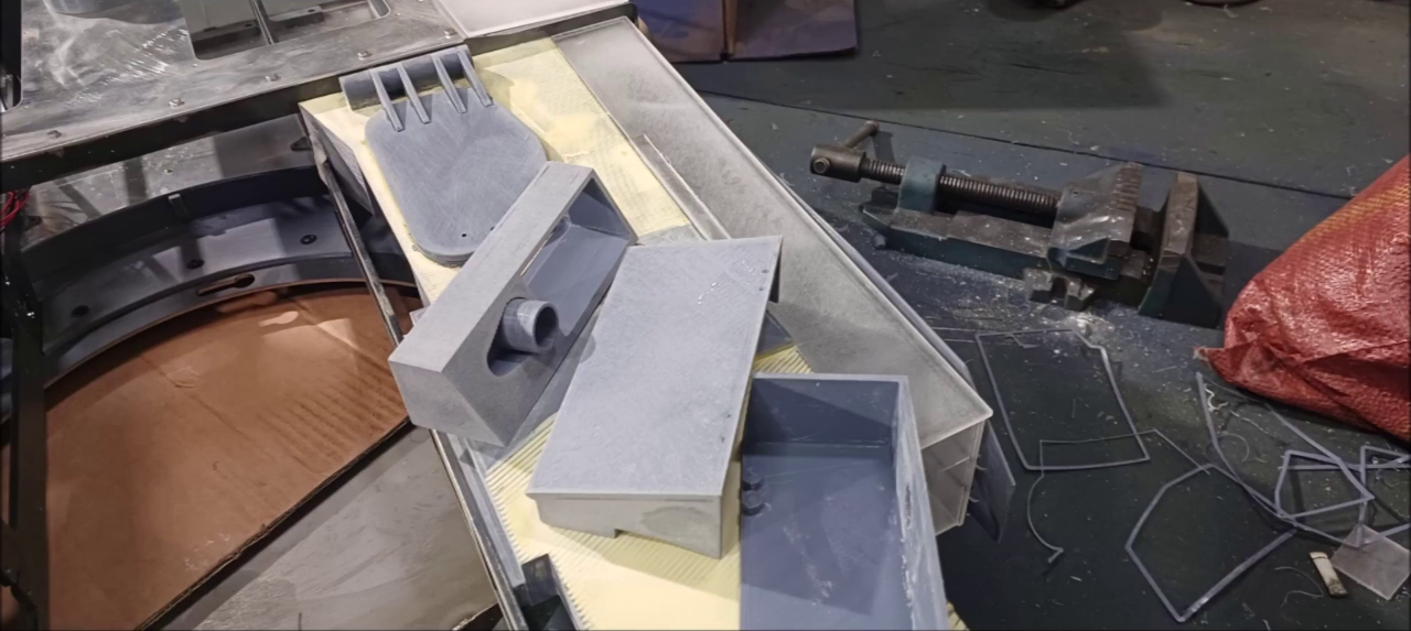
Side skirt inner shape
Side skirt inner shape
Side skirt inner shape
Before installing the fixture between the left side skirt side fixture and the body
Before installing the fixture between the left side skirt side fixture and the body
Before installing the fixture between the right side skirt side fixture and the body
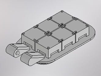
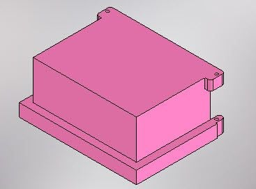
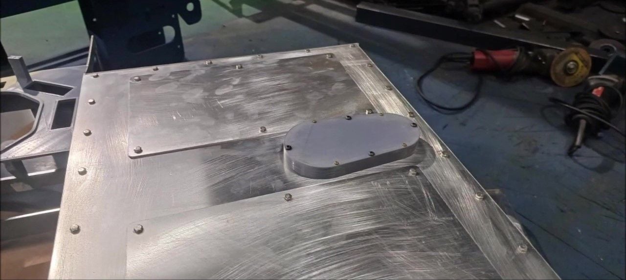
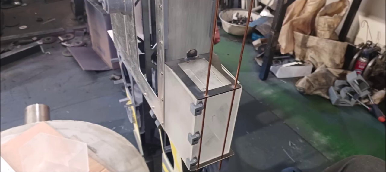
Position and cover the main control box
Position and cover the main control box
Position and cover the main control box
The work on this episode has been completed. I'm going to work on it next week
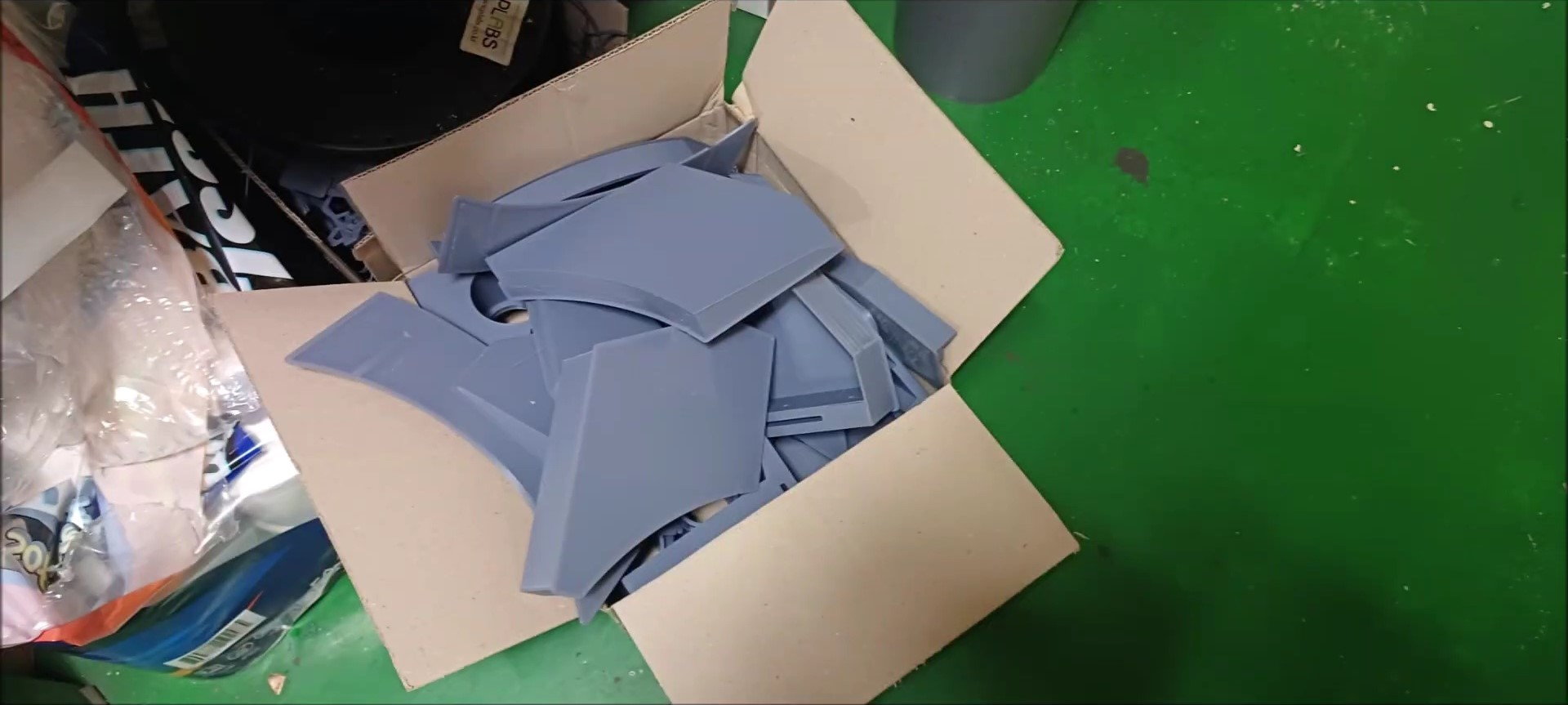
Prepare 3D printer printouts to make up turrets
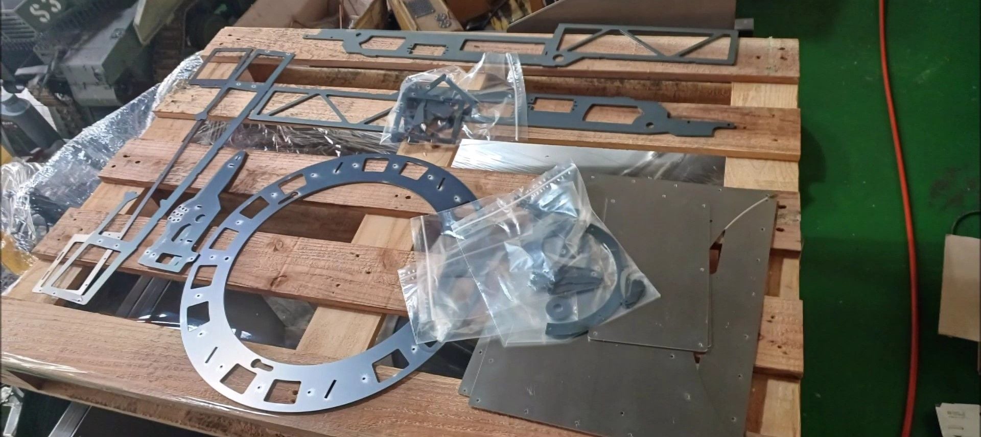
Steel structures to be used in turrets are also ready
That's it for this week. It will continue in the next episode.
09-25-2023, 11:46 PM
#134
Thread Starter
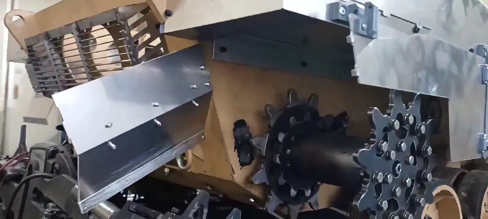
The left and right rear mud guards of the K2 tank were installed and the inspection was validated when the rear side skirt was opened to check the caterpillar.
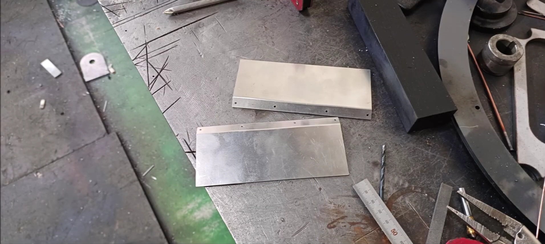
Left Rear Mud Guard
Right Rear Mud Guard
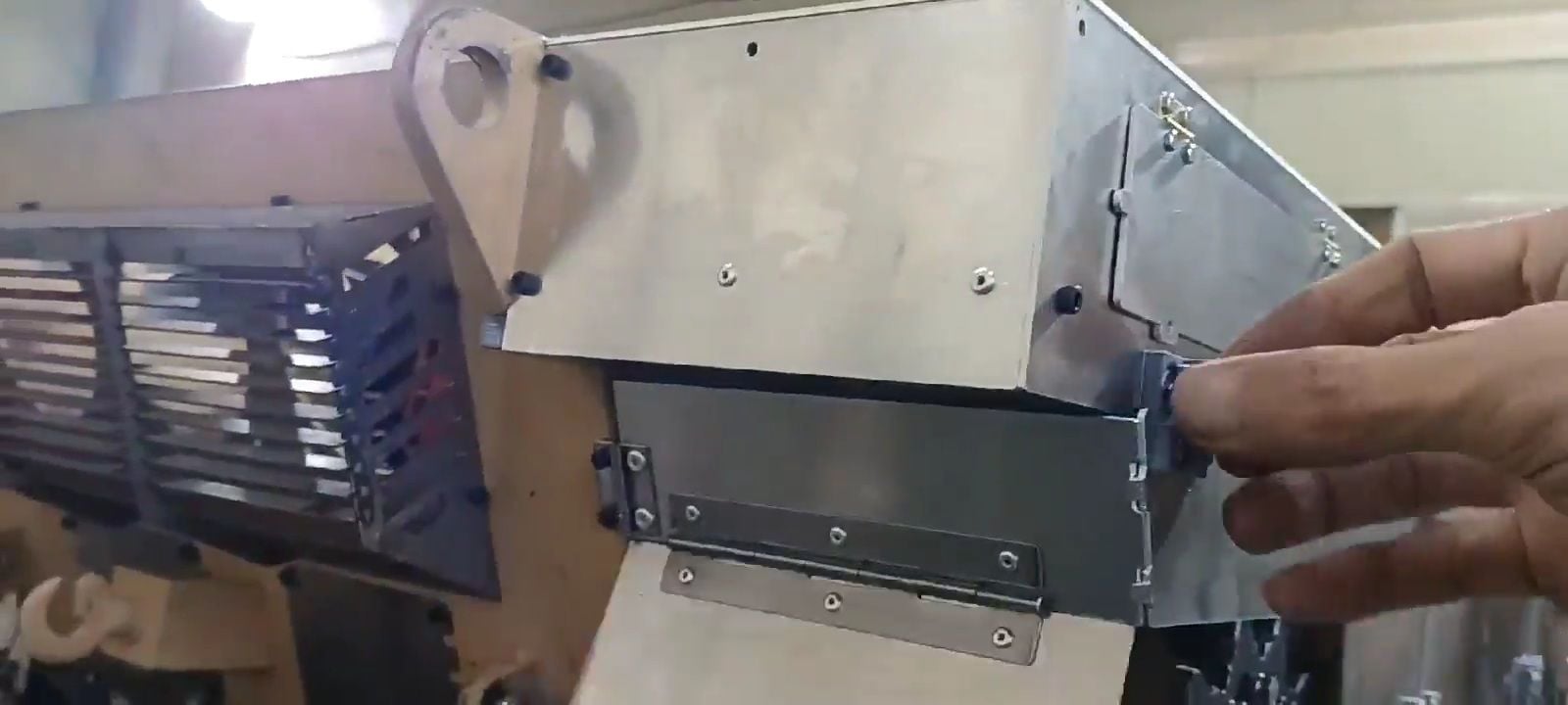
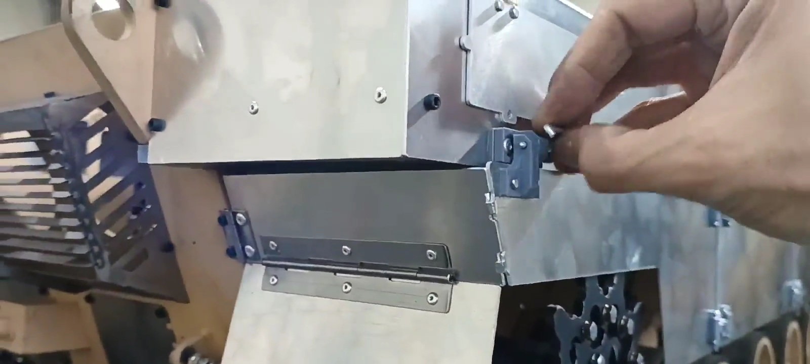
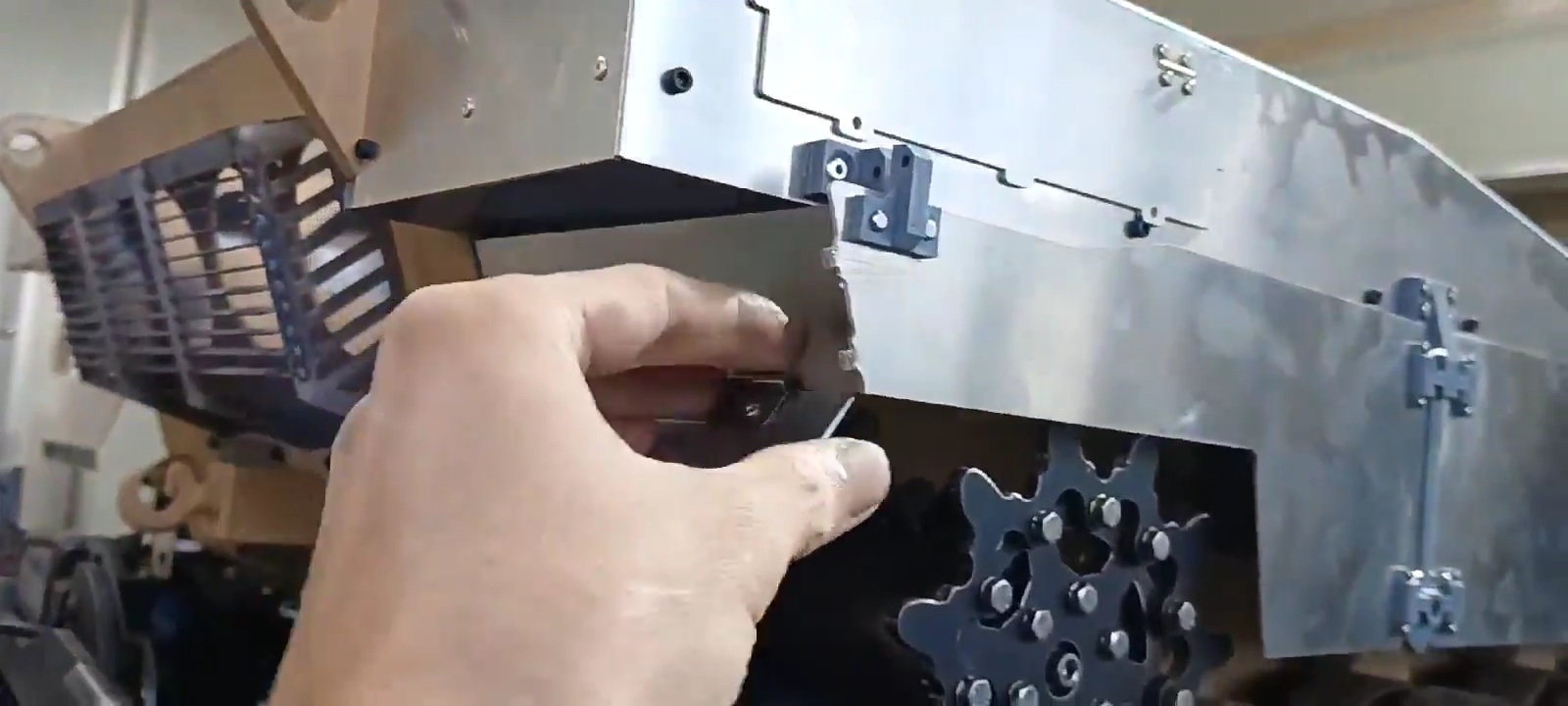
The process of opening the mudguard by removing the right rear side skirt
The process of opening the mudguard by removing the right rear side skirt
The process of opening the mudguard by removing the right rear side skirt
The process of opening the mudguard by removing the right rear side skirt
The process of opening the mudguard by removing the right rear side skirt
Process of installing mud guards by requesting a right rear side skirt
Process of installing mud guards by requesting a right rear side skirt
Process of installing mud guards by requesting a right rear side skirt
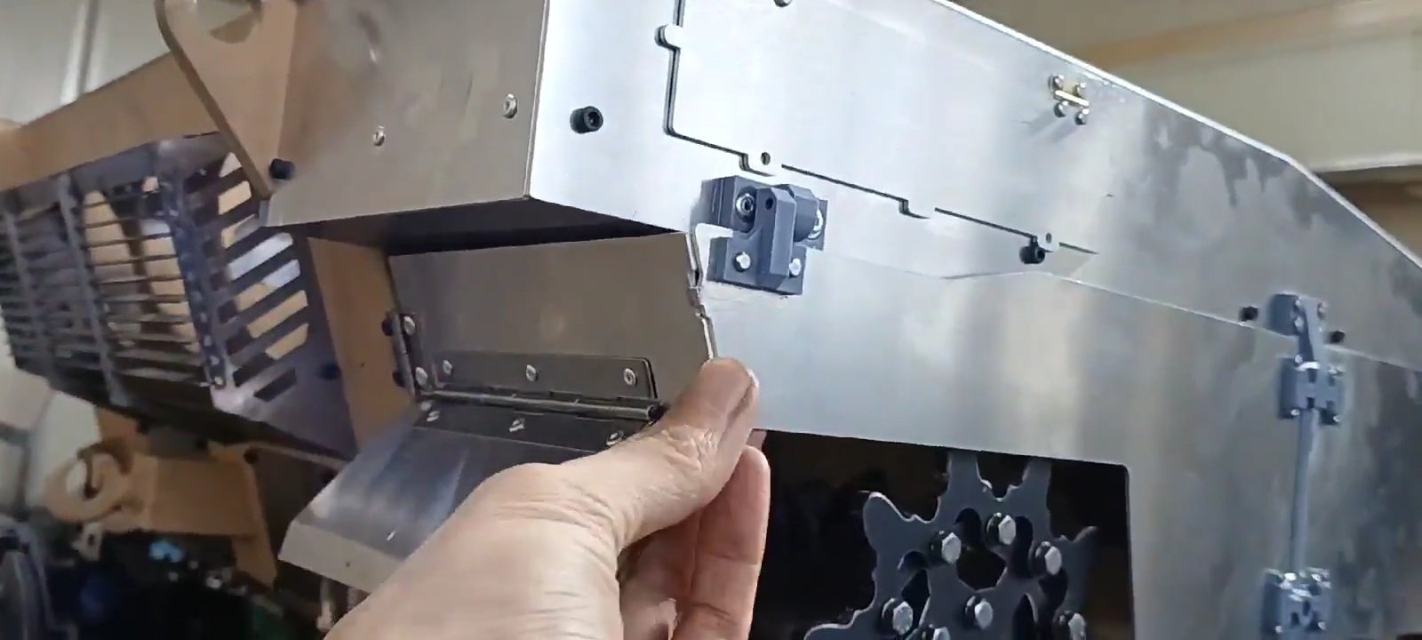
Process of installing mud guards by requesting a right rear side skirt
Process of installing mud guards by requesting a right rear side skirt
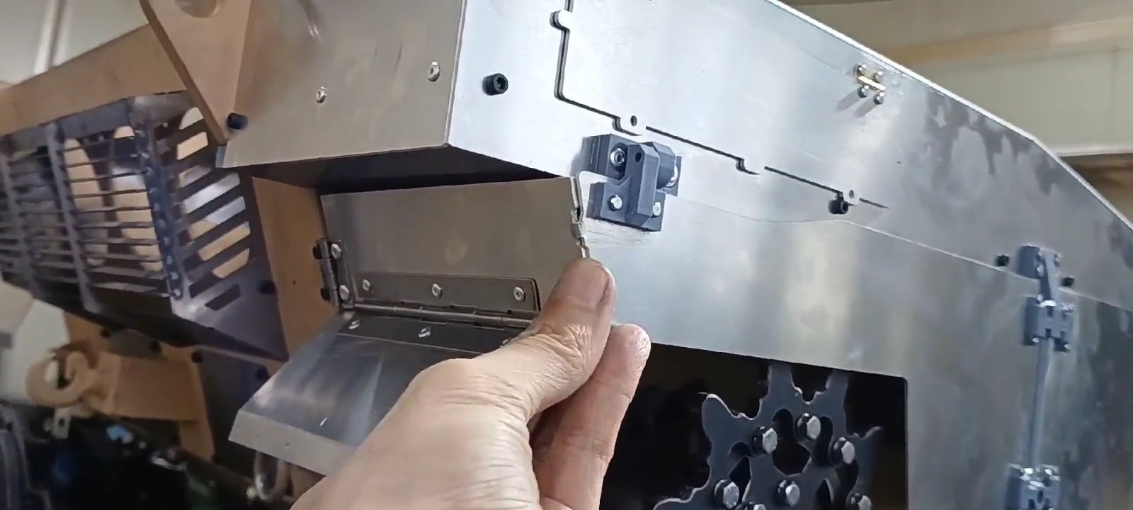
Right rear mudguard action
Right rear mudguard action
Right rear mudguard action
Right rear mudguard action
Gravity brings it down naturally
Gravity brings it down naturally
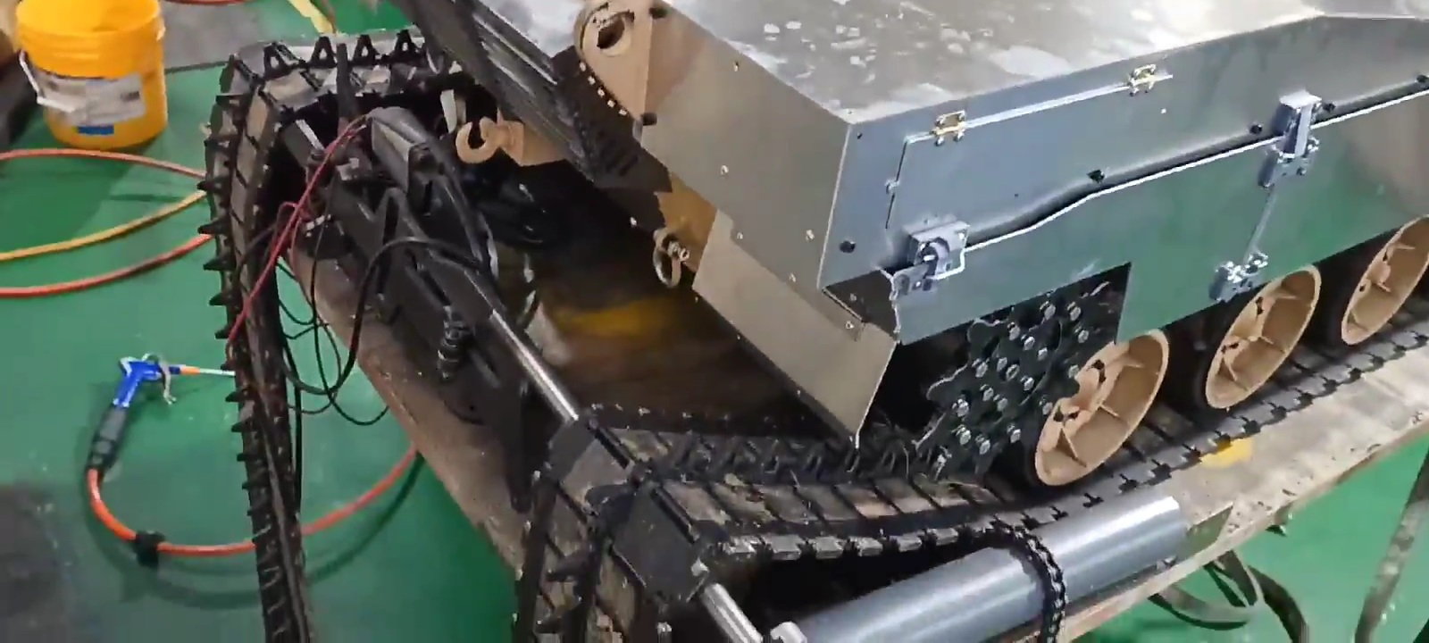
The rear mud guard with only rubber work left
Left Rear Mud Guard
Right Rear Mud Guard
The process of opening the mudguard by removing the right rear side skirt
The process of opening the mudguard by removing the right rear side skirt
The process of opening the mudguard by removing the right rear side skirt
The process of opening the mudguard by removing the right rear side skirt
The process of opening the mudguard by removing the right rear side skirt
Process of installing mud guards by requesting a right rear side skirt
Process of installing mud guards by requesting a right rear side skirt
Process of installing mud guards by requesting a right rear side skirt
Process of installing mud guards by requesting a right rear side skirt
Process of installing mud guards by requesting a right rear side skirt
Right rear mudguard action
Right rear mudguard action
Right rear mudguard action
Right rear mudguard action
Gravity brings it down naturally
Gravity brings it down naturally
The rear mud guard with only rubber work left
Last edited by PE YOUNG; 09-26-2023 at 12:05 AM.
The following users liked this post:
tankme (09-26-2023)
09-27-2023, 01:09 AM
#135
Thread Starter
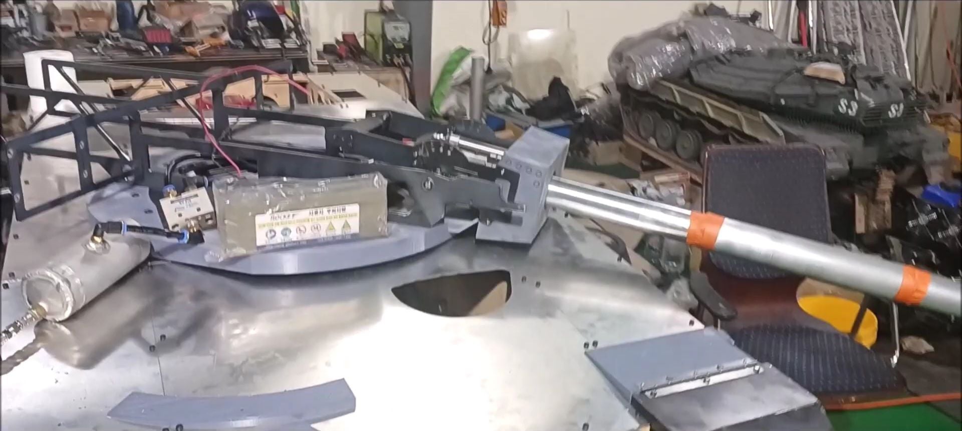
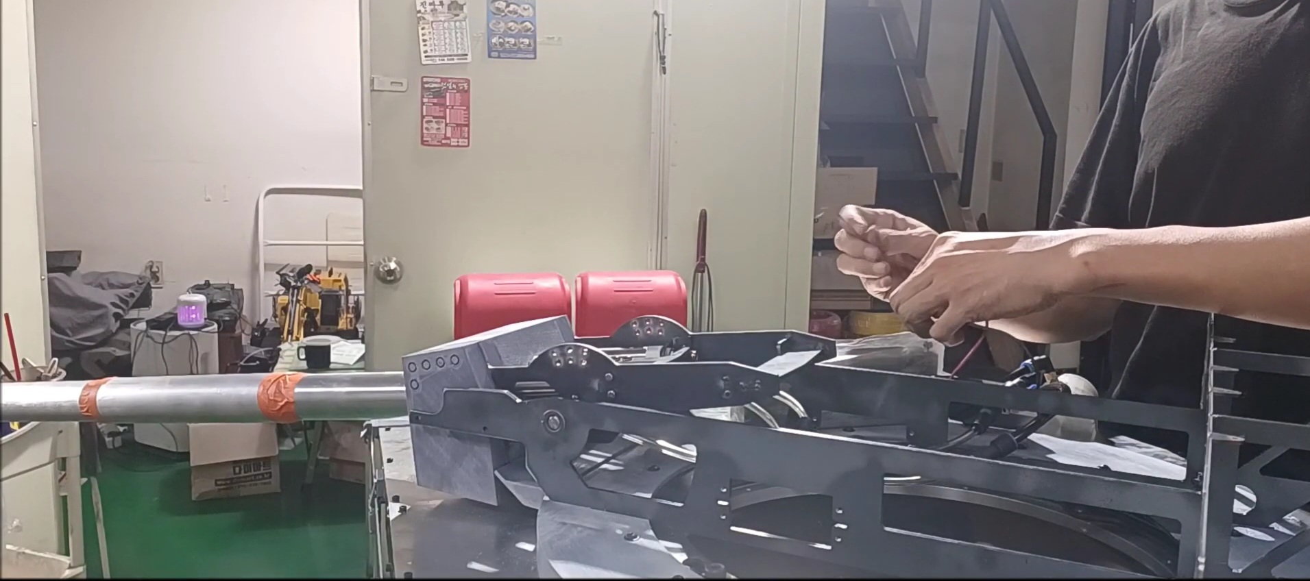
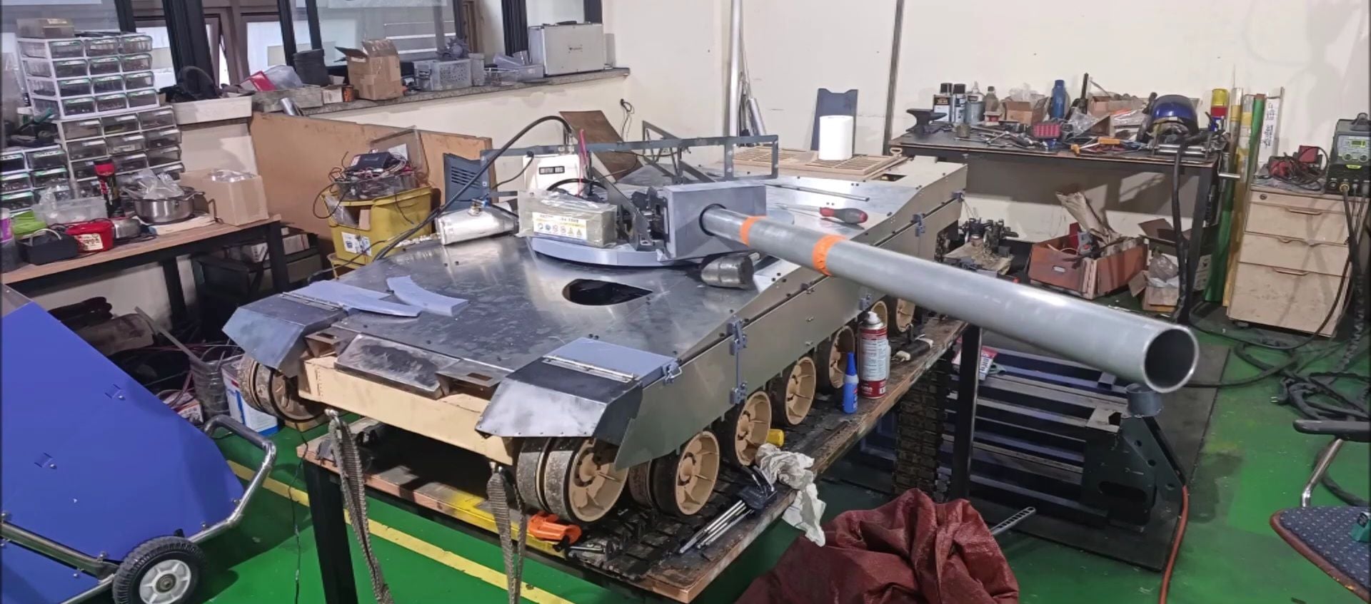
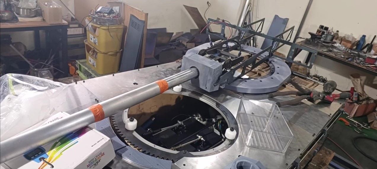
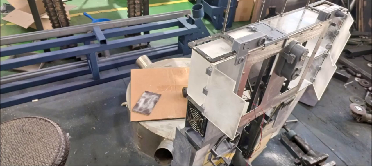
The turret's frame was constructed from the prepared K2 tank's turret structural materials, and the main gun was applied with pneumatic recoil.
The work video will be edited and shared on YouTube soon.
In Korea, the traditional holiday of Chuseok begins tomorrow.
I hope you all enjoy the rich autumn.
Regards,
Young
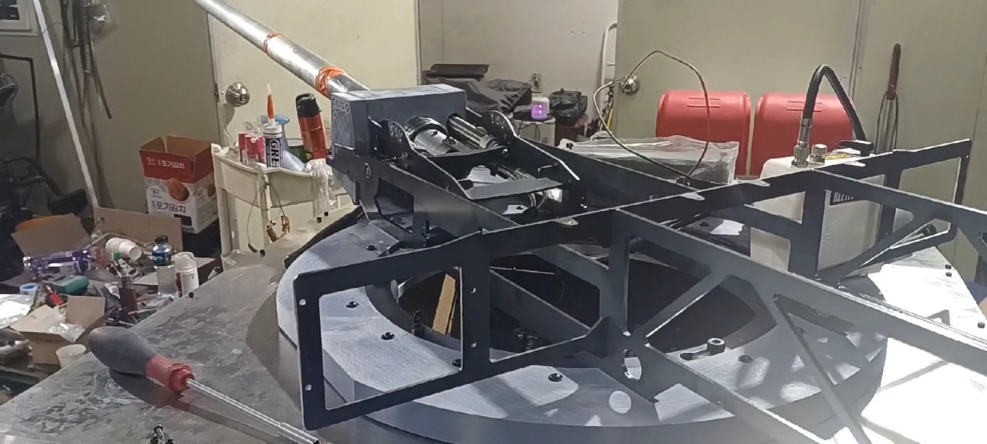
Turret frame and recoil work of main gun
The work video will be edited and shared on YouTube soon.
In Korea, the traditional holiday of Chuseok begins tomorrow.
I hope you all enjoy the rich autumn.
Regards,
Young
Turret frame and recoil work of main gun
09-28-2023, 05:25 AM
#137
Has anyone else had trouble viewing this thread on your phone? Lately when I come here and click on "view first unread" it locks up my phone for a good 3 or 4 minutes. I think that's because there's just so many photos to load in this thread. It might be time to end this one and start a "Part 2".
09-28-2023, 05:30 AM
#138
And it just did it again when I posted above. The phone won't do anything for 2 or 3 minutes and then it acts like I restarted it. And this is the only thread it does that on. I think it's just because the threat has gotten so long and there's sooo much information that has to load that my phone just kind of freaks out.
09-28-2023, 02:07 PM
#139
With all the high quality pics and video links, it does the same thing on my desktop sometimes.
 09-28-2023, 05:46 PM
#140
Thread Starter
There's something wrong with this thread that we didn't even think about. I'm sorry for the unintentional inconvenience. We will complete the K2 tank soon and then close this thread.
09-28-2023, 09:53 PM
#141
Thread Starter
Here's a photo description of this week's episode 29.
The front fender is made of 1.6t steel
The upper plate of the fender was intended to be bent, but it was manufactured by welding after cutting to make the connection line straight
The front fender parts were welded
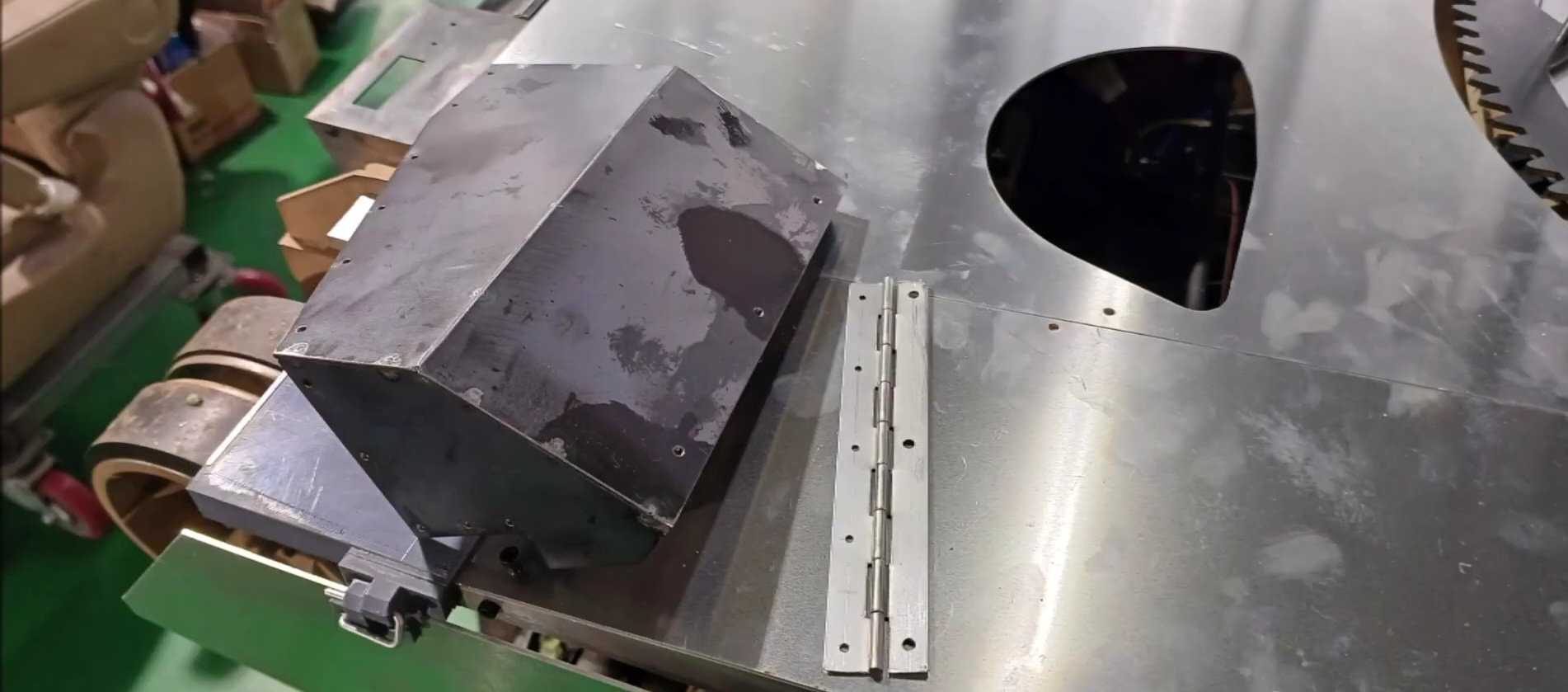
The connection between the front fender and the body is made using a piano hinge
Operation test
The finishing rubber work will be carried out after painting is completed
Front fender operation complete
Rear Mudguard Operations
Rear Mudguard Operations
Rear Mudguard Operations
Rear mudguard operation (see teaser and video posted earlier)
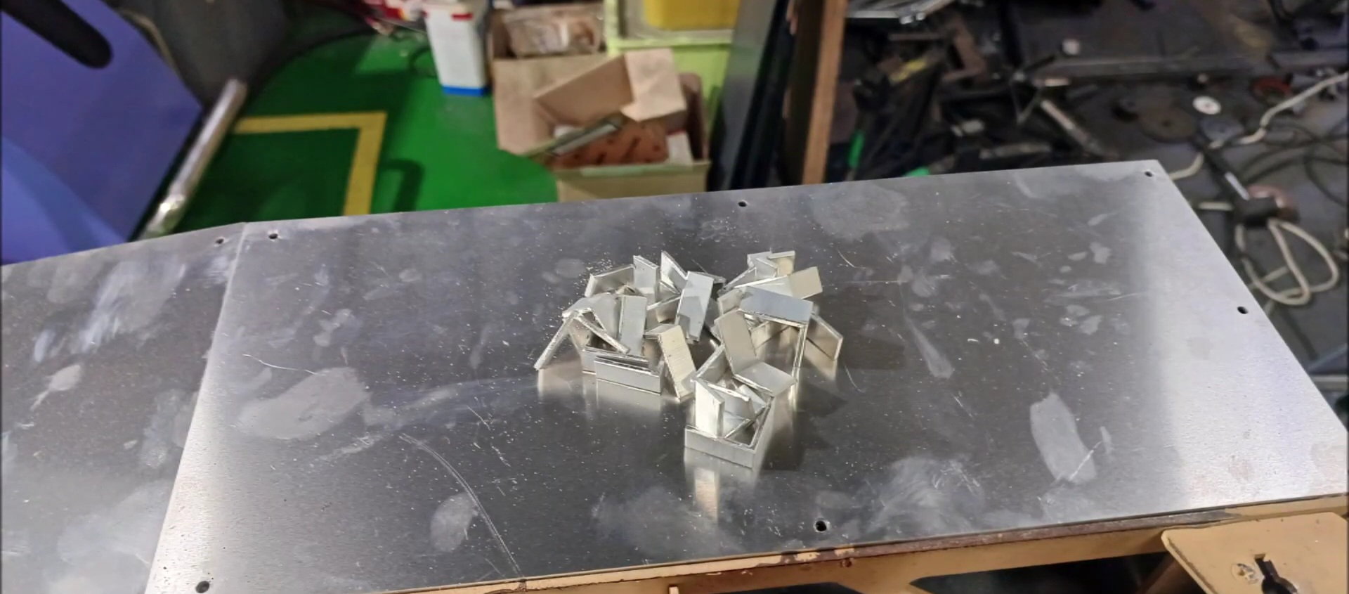
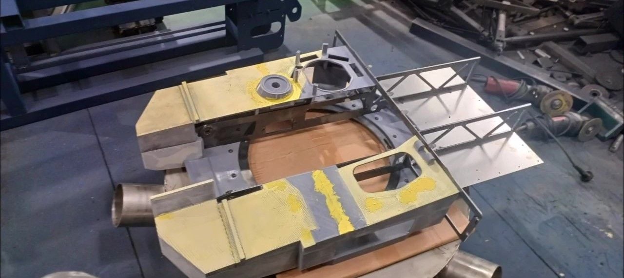
Aluminium Angle Pieces to Support Body Skin
Use rivets to secure pieces of aluminum angle
Use rivets to secure pieces of aluminum angle
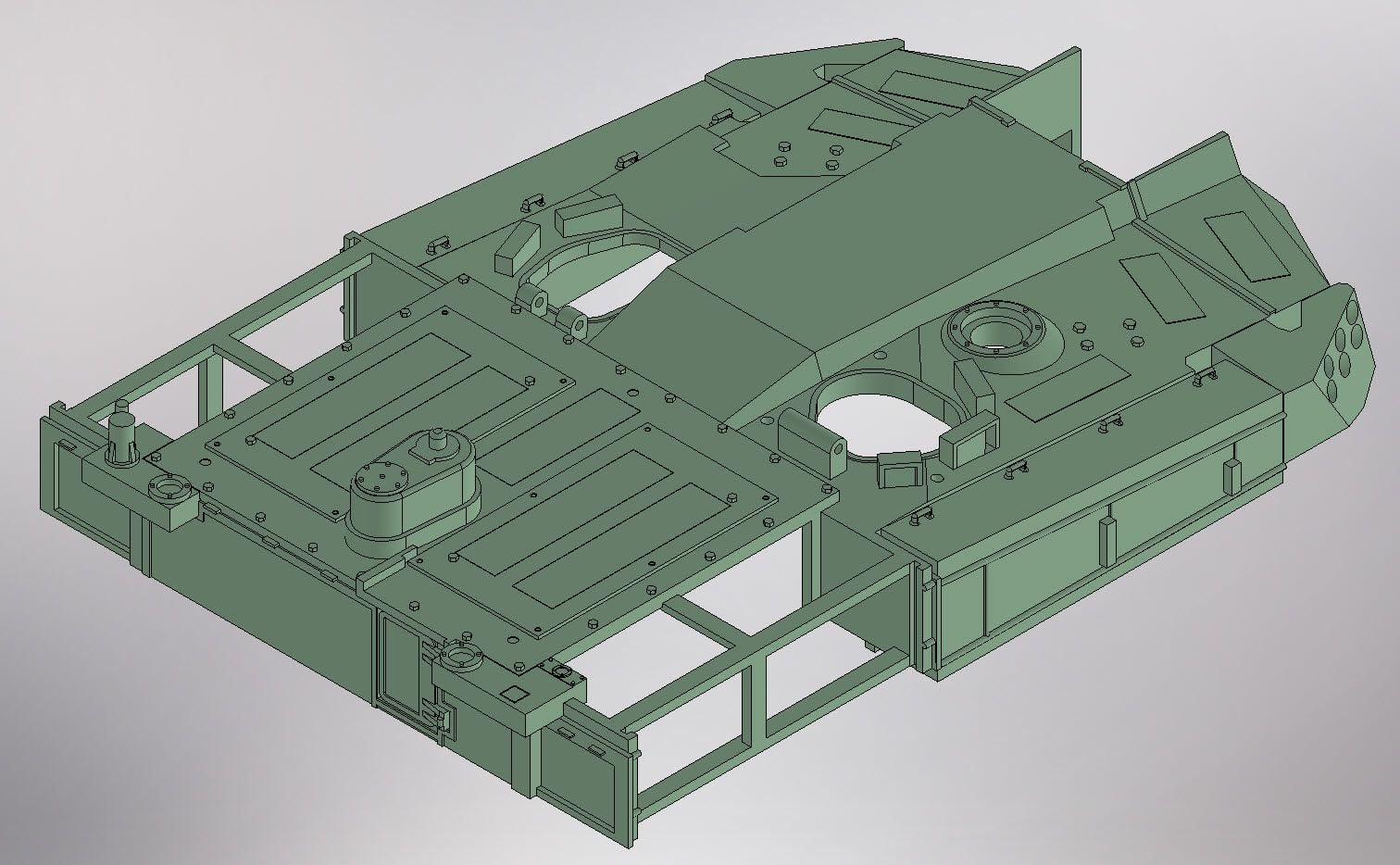
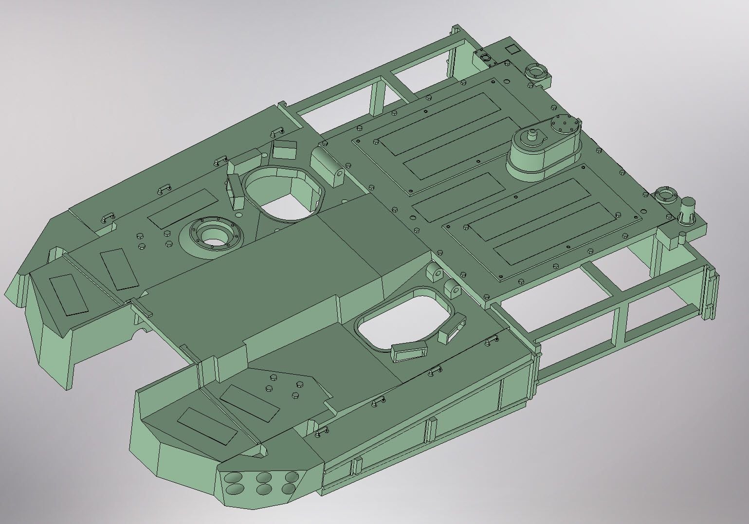
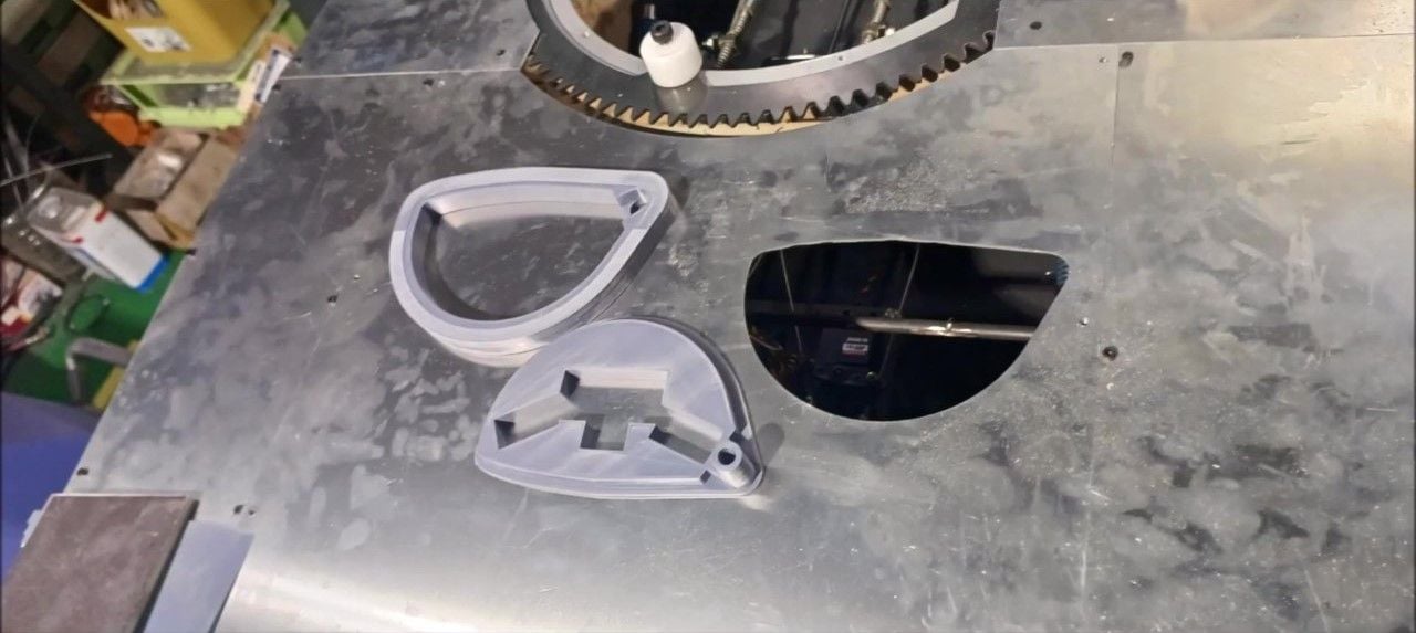
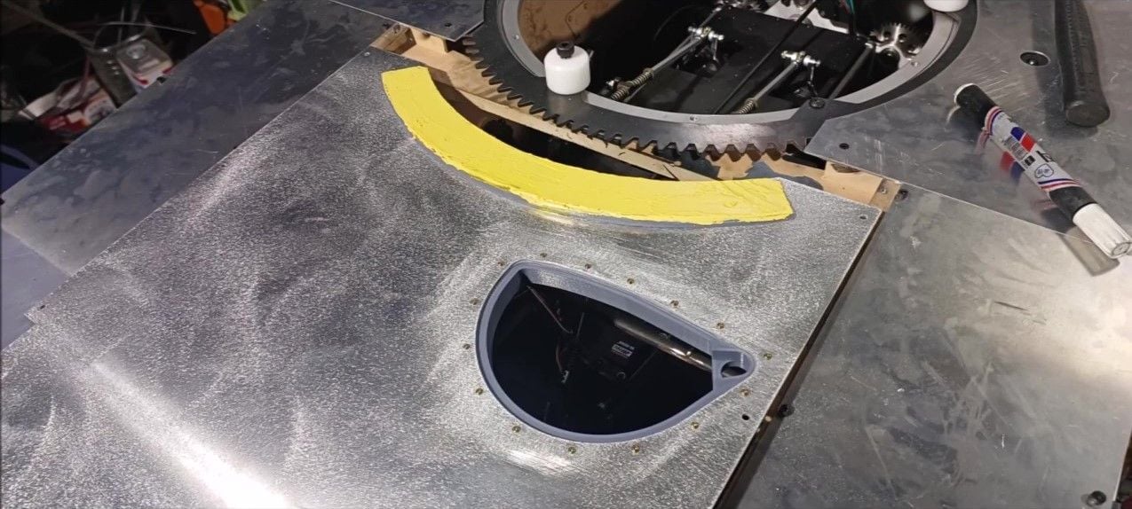
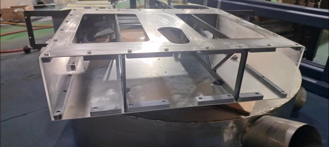
The hole was created during the design stage in anticipation of the turret rotating motor shaft sticking out, but the hole will be eliminated on the design drawing due to no shaft protrusion or interference
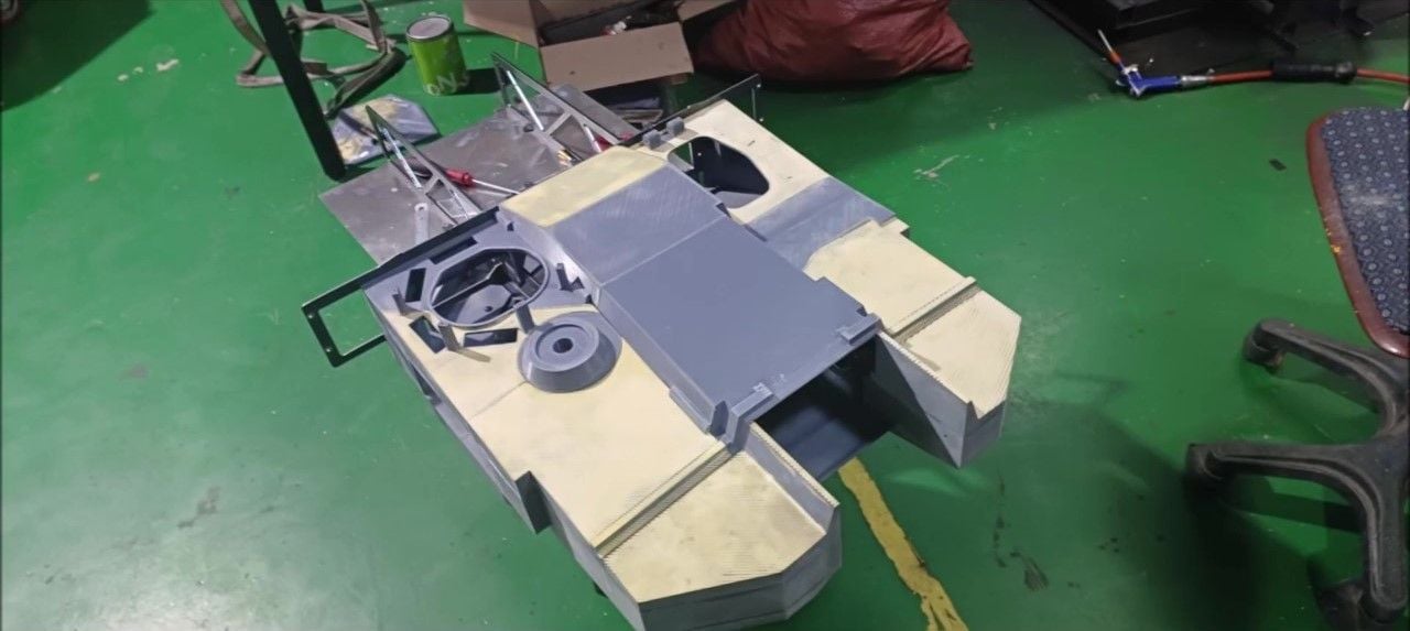
Completion of body shape except the detail
Completion of body shape except the detail
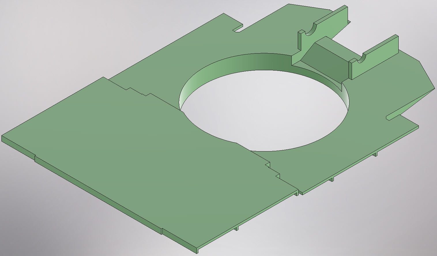
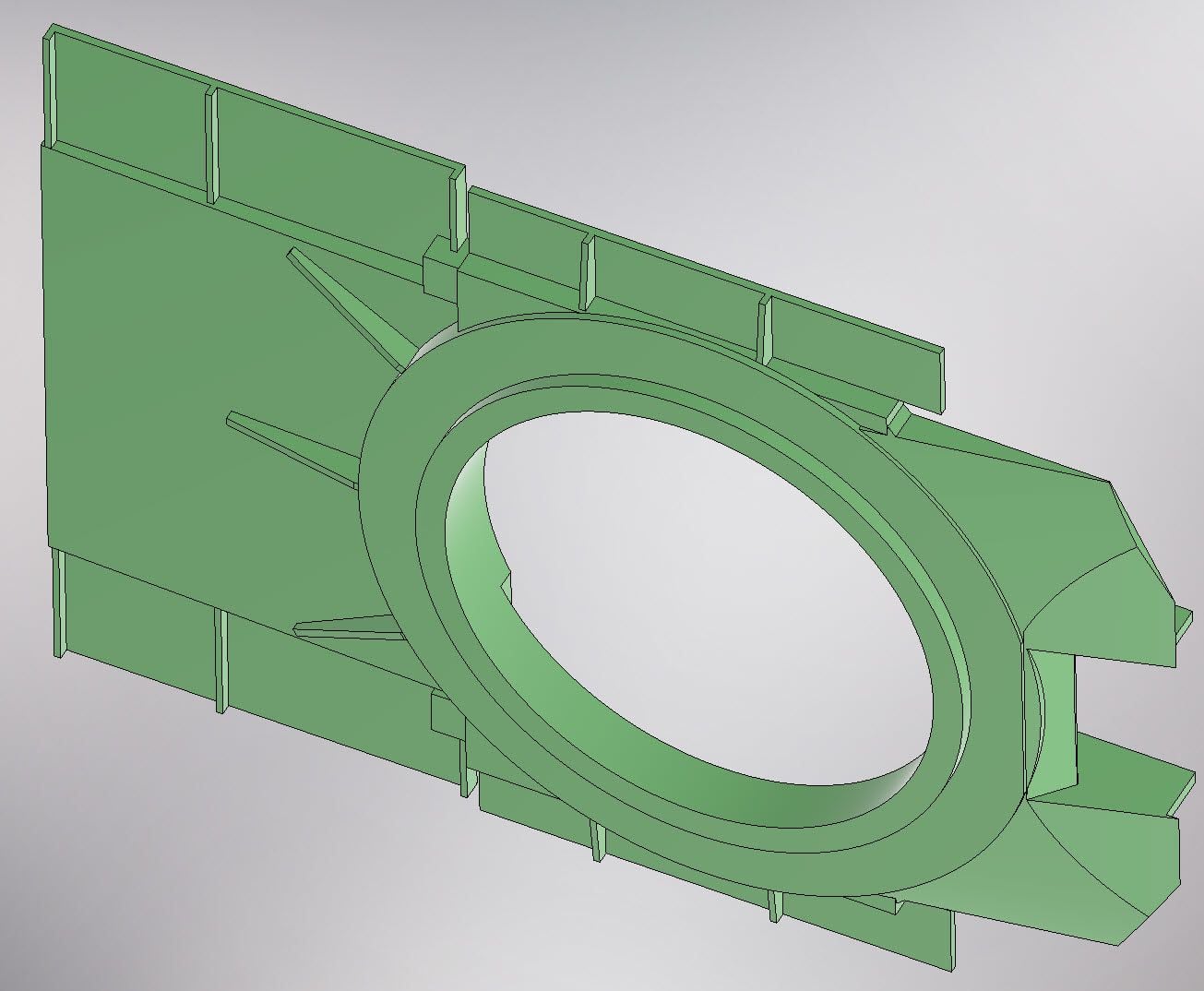
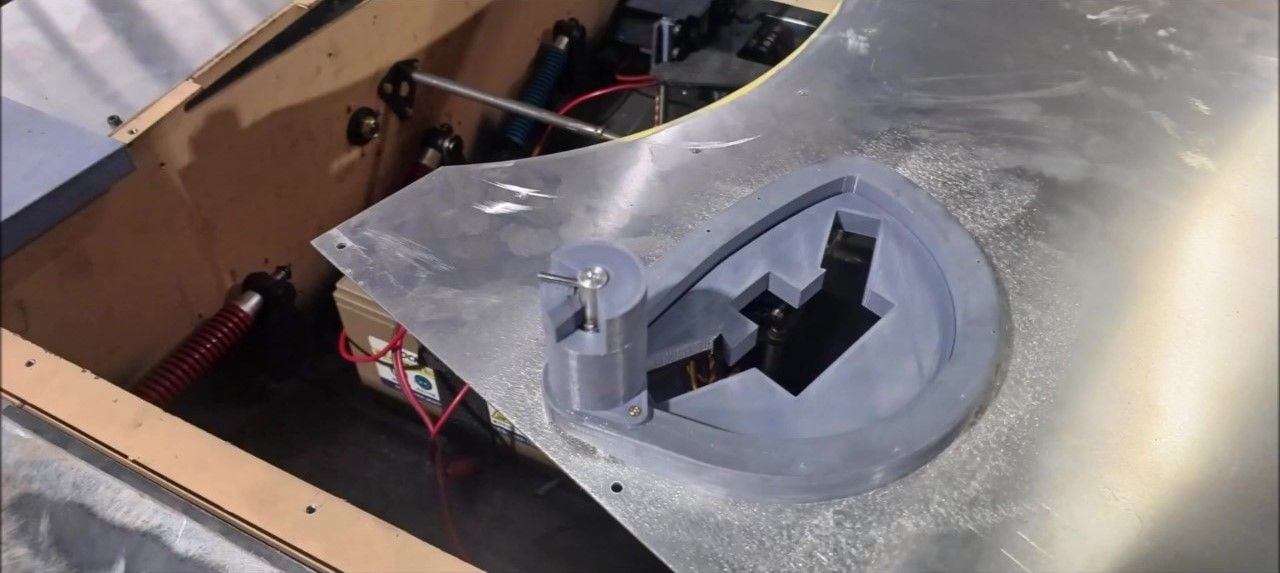
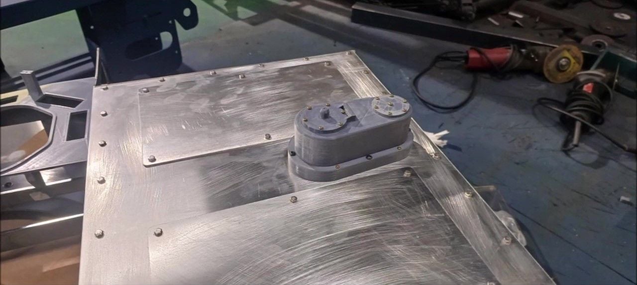
The turret gear shield will be secured in that position
Completion of body shape except the detail
Completion of body shape except the detail
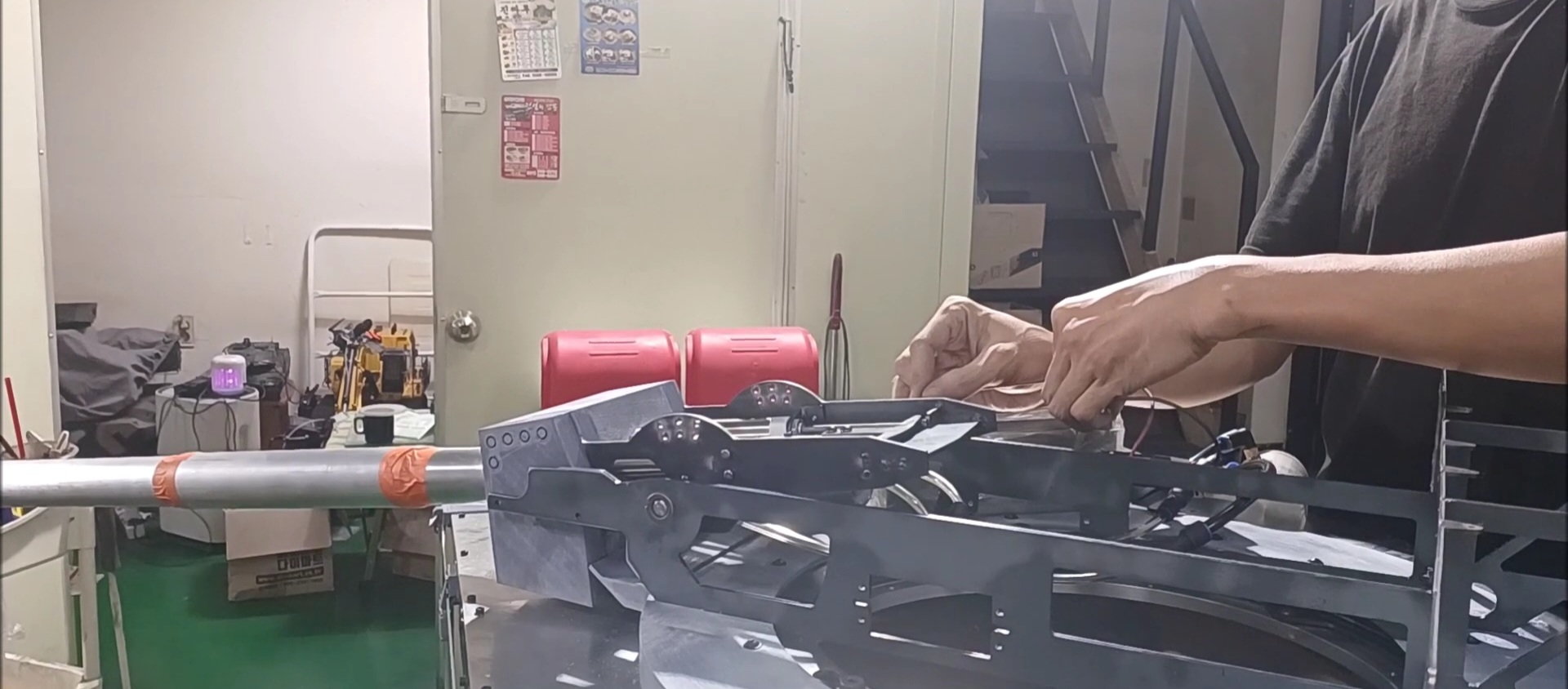
Assembley for holding cannons
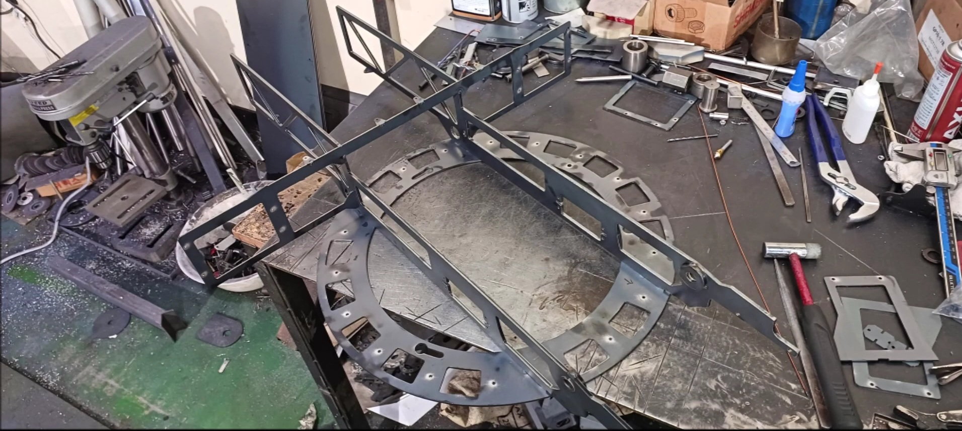
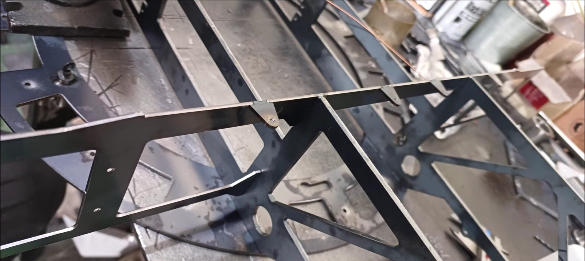
The frame to make up the turret was made of 4mm steel
It was constructed by welding parts for holding cannons.
Fabrication of cannon shield internal structure to support cannon
Preparation of connecting 3D parts and turret structures for the lower finish of the turret
The front fender is made of 1.6t steel
The upper plate of the fender was intended to be bent, but it was manufactured by welding after cutting to make the connection line straight
The front fender parts were welded
The connection between the front fender and the body is made using a piano hinge
Operation test
The finishing rubber work will be carried out after painting is completed
Front fender operation complete
Rear Mudguard Operations
Rear Mudguard Operations
Rear Mudguard Operations
Rear mudguard operation (see teaser and video posted earlier)
Aluminium Angle Pieces to Support Body Skin
Use rivets to secure pieces of aluminum angle
Use rivets to secure pieces of aluminum angle
The hole was created during the design stage in anticipation of the turret rotating motor shaft sticking out, but the hole will be eliminated on the design drawing due to no shaft protrusion or interference
Completion of body shape except the detail
Completion of body shape except the detail
The turret gear shield will be secured in that position
Completion of body shape except the detail
Completion of body shape except the detail
Assembley for holding cannons
The frame to make up the turret was made of 4mm steel
It was constructed by welding parts for holding cannons.
Fabrication of cannon shield internal structure to support cannon
Preparation of connecting 3D parts and turret structures for the lower finish of the turret
09-28-2023, 10:18 PM
#142
Thread Starter
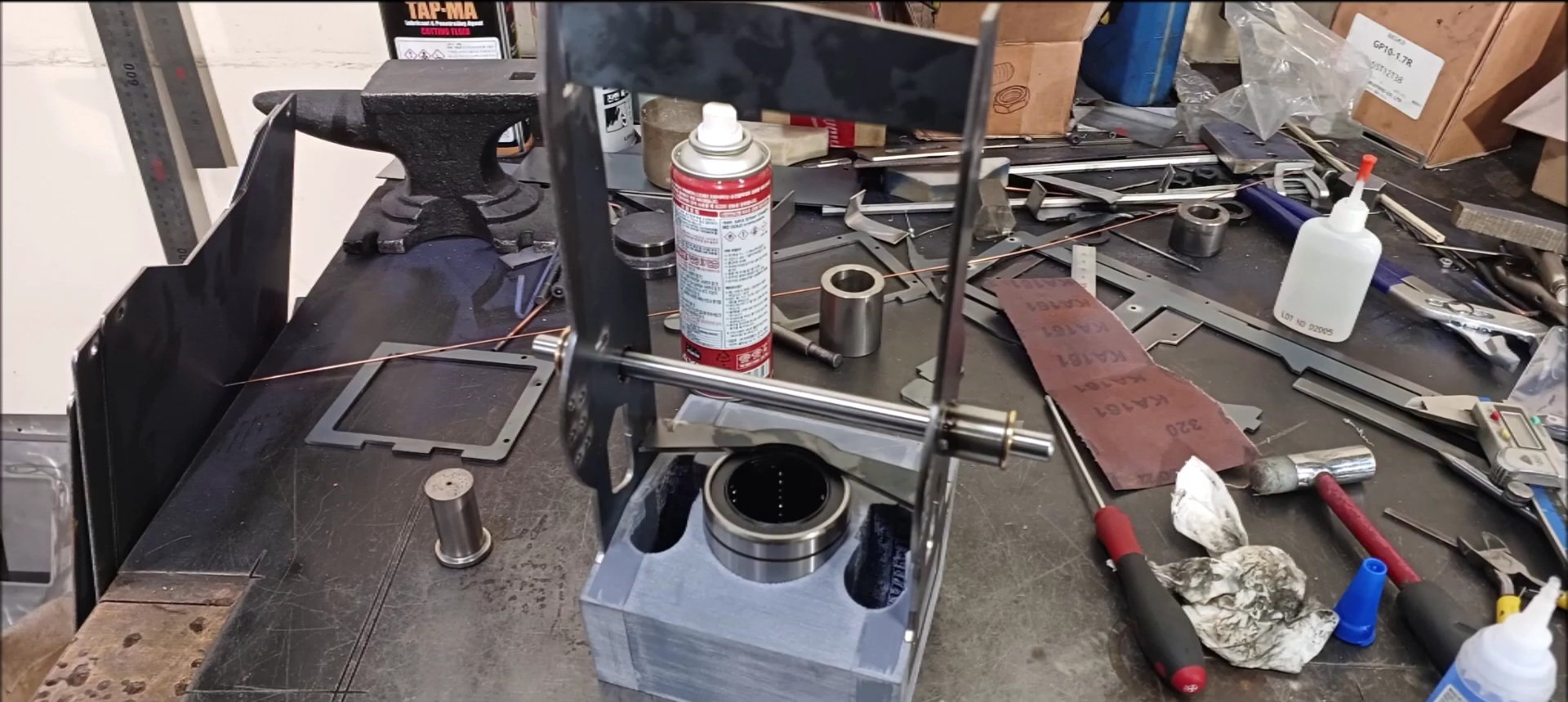
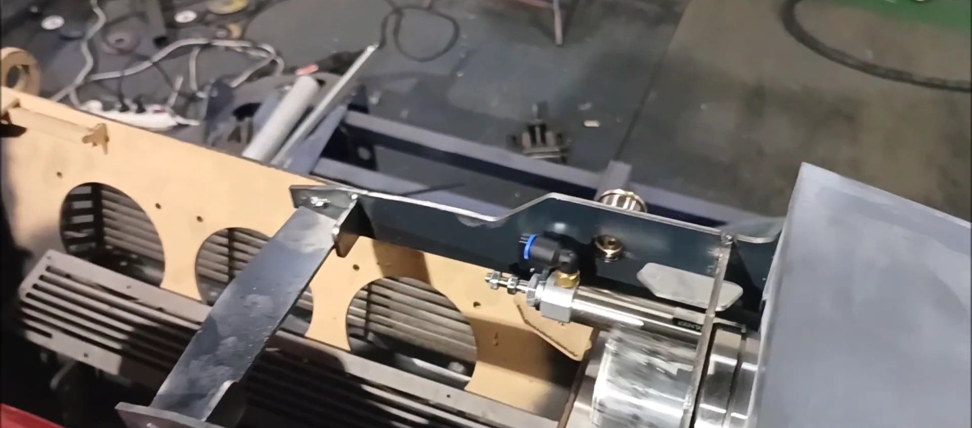
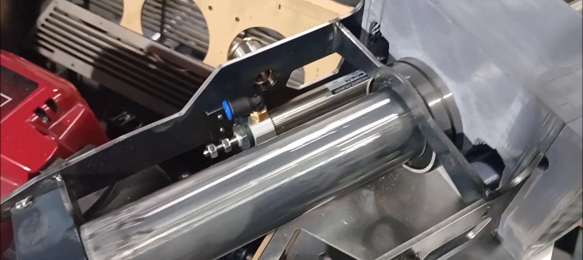
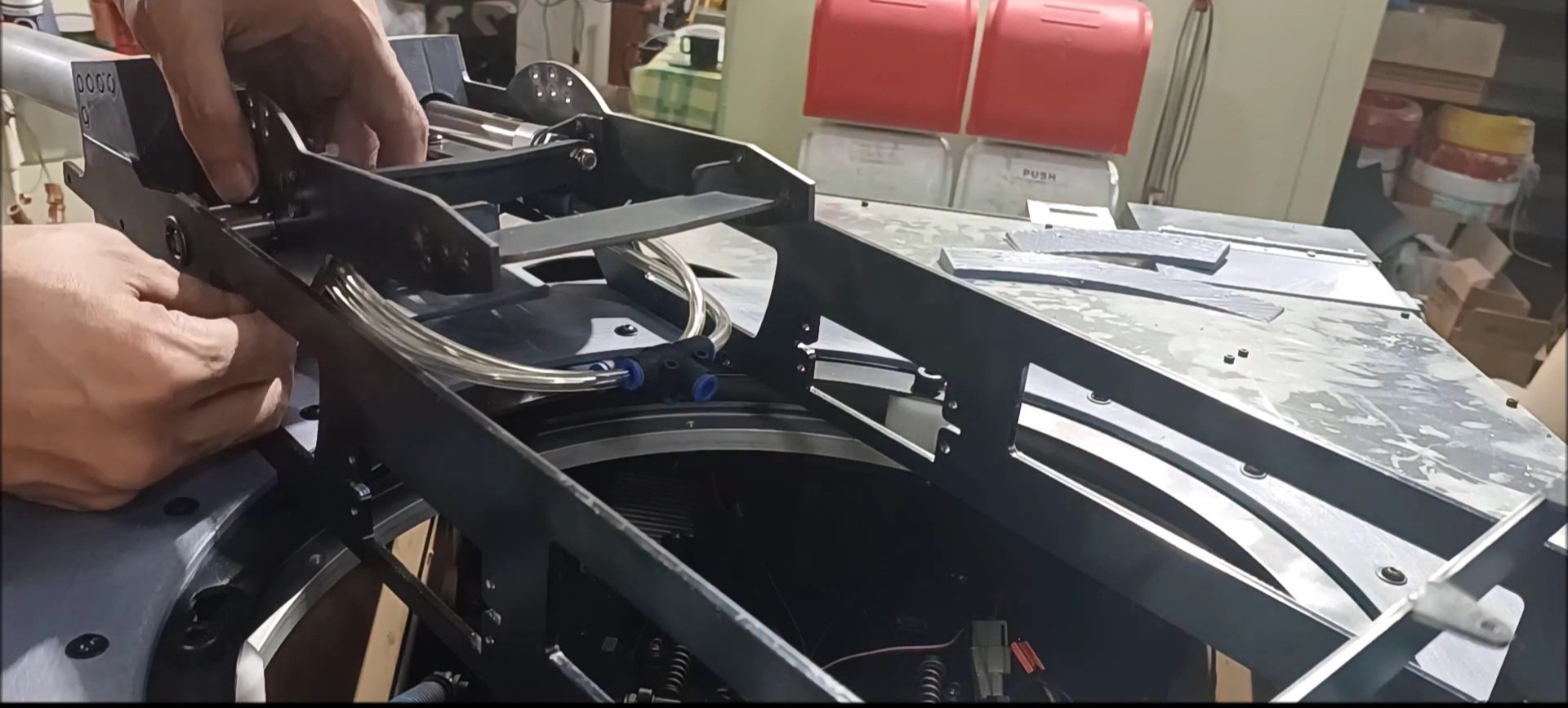
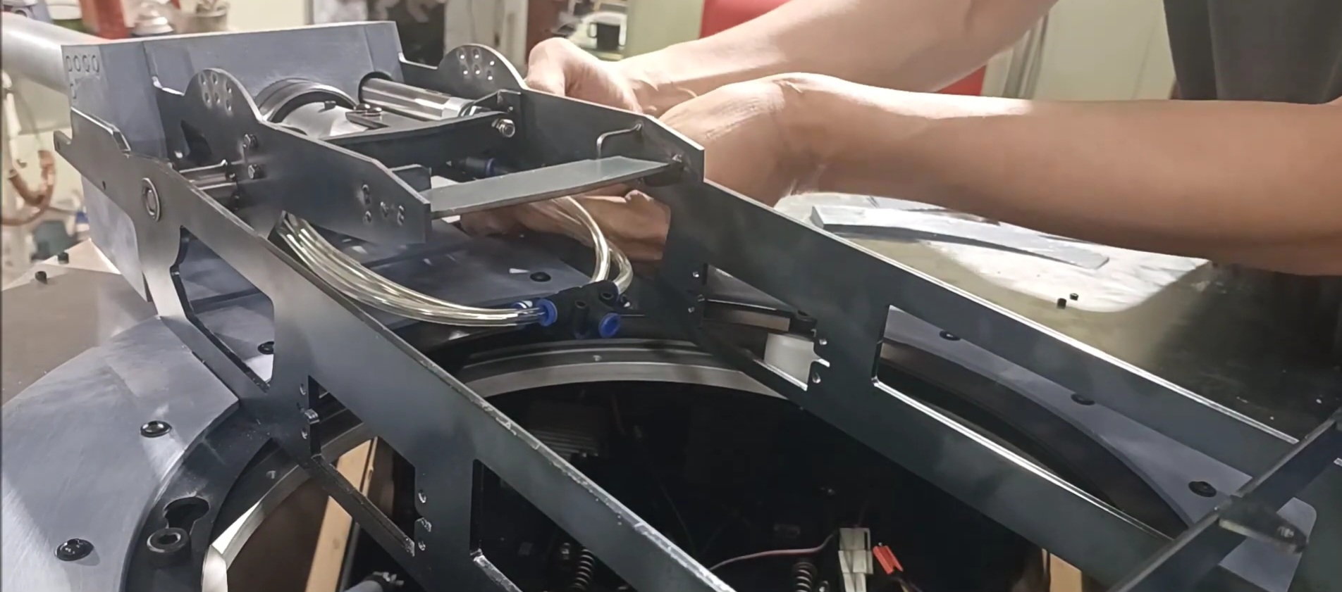
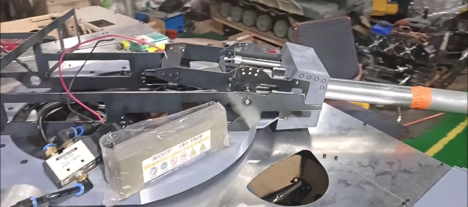
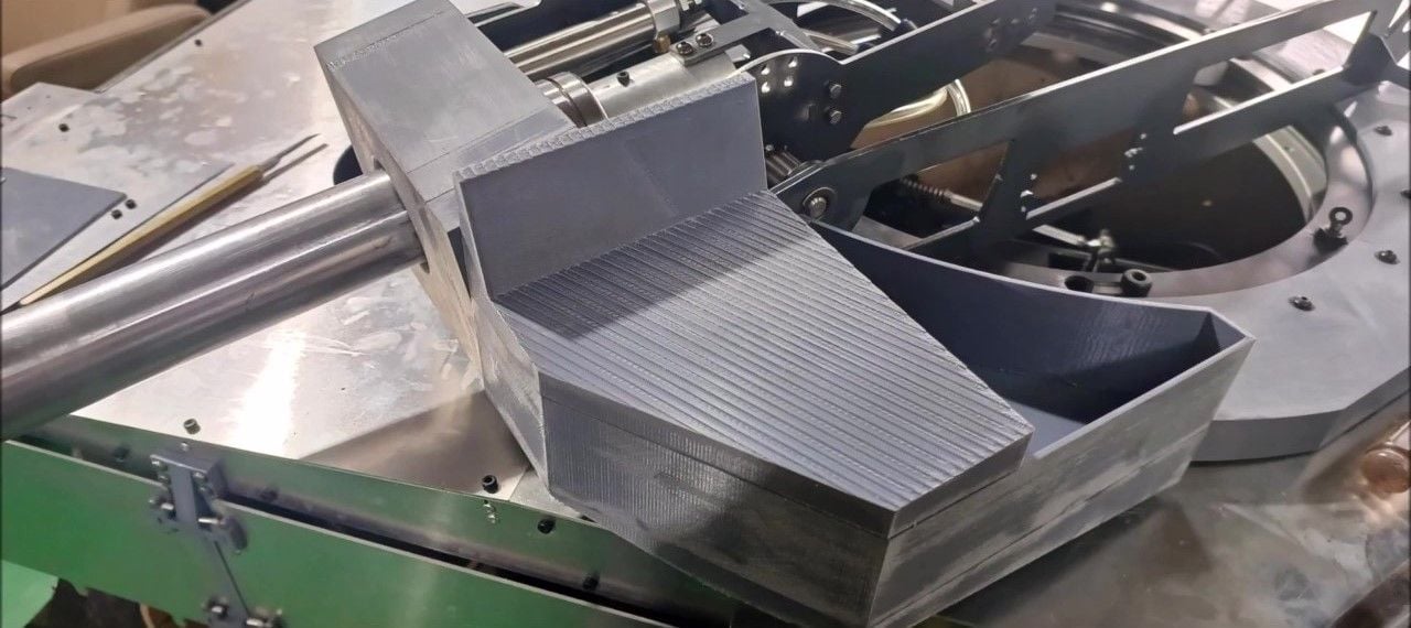
This version of the recoil is pneumatic and the sliding uses linear bearings.
Secure linear bearing to cannon shield
Pneumatic cylinder installation
Installation of left and right pneumatic cylinders and main recuperator (pre-operation stroke reference point)
Installation of left and right pneumatic cylinders and main recuperator (stroke stop point after operation)
Welding the internal structure of the turret
Welding the turret rear upper plate support
Manufacture of turret fixing pins
Teflon installation for turret spacers
Connecting the turret structure to the lower rotating bearing
Connecting the turret structure to the lower rotating bearing
Check the operation of the turret fixing pin
Organize 3D printer structures for turret bottom finish
3D printer output arrangement for turret bottom finish
3D printer output arrangement for turret bottom finish
3D printer output arrangement for turret bottom finish
3D printer output arrangement for turret bottom finish
3D printer output arrangement for turret bottom finish
Manufacture of bolt hole after 3D printer printout arrangement for turret bottom finish
Secure with bolts
Installation of cannon supports on turret structures
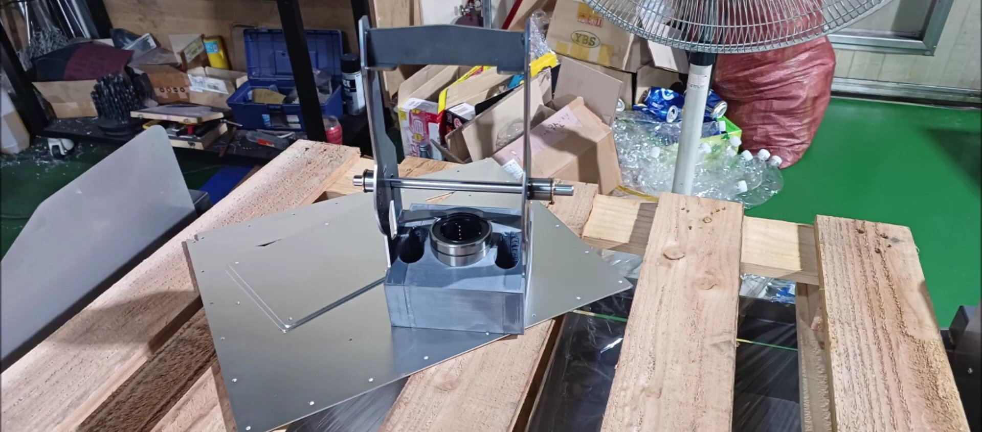
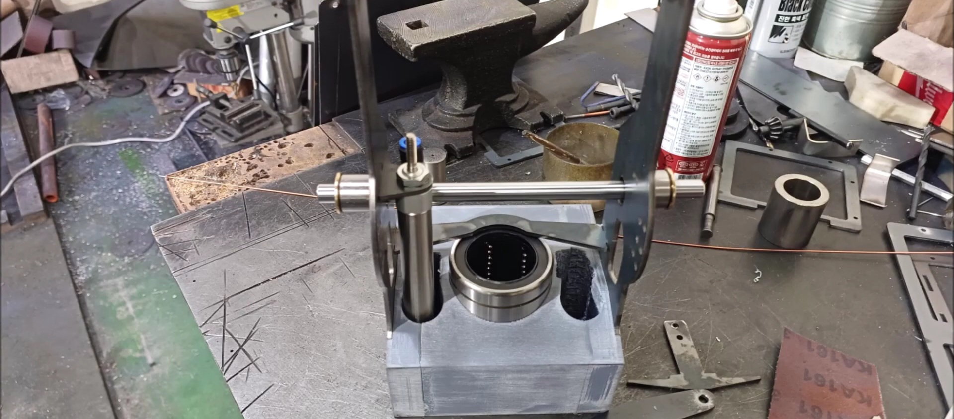
cannon shield inner linear bearing
cannon shield inner linear bearing
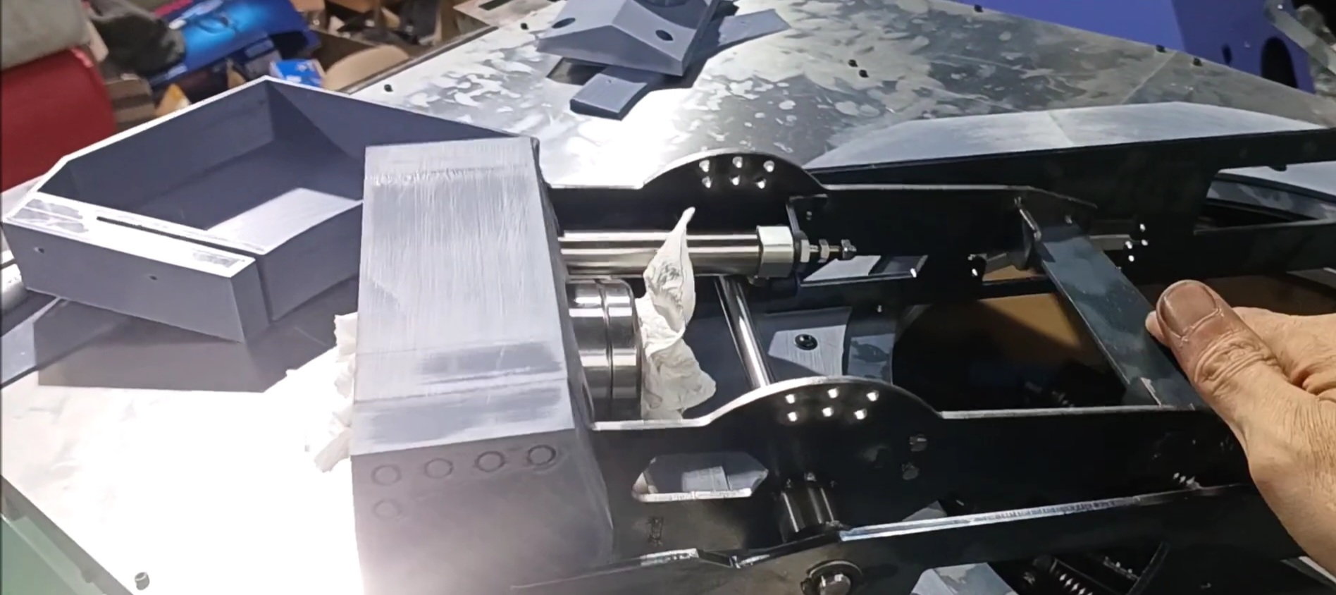
cannon shield inner linear bearing
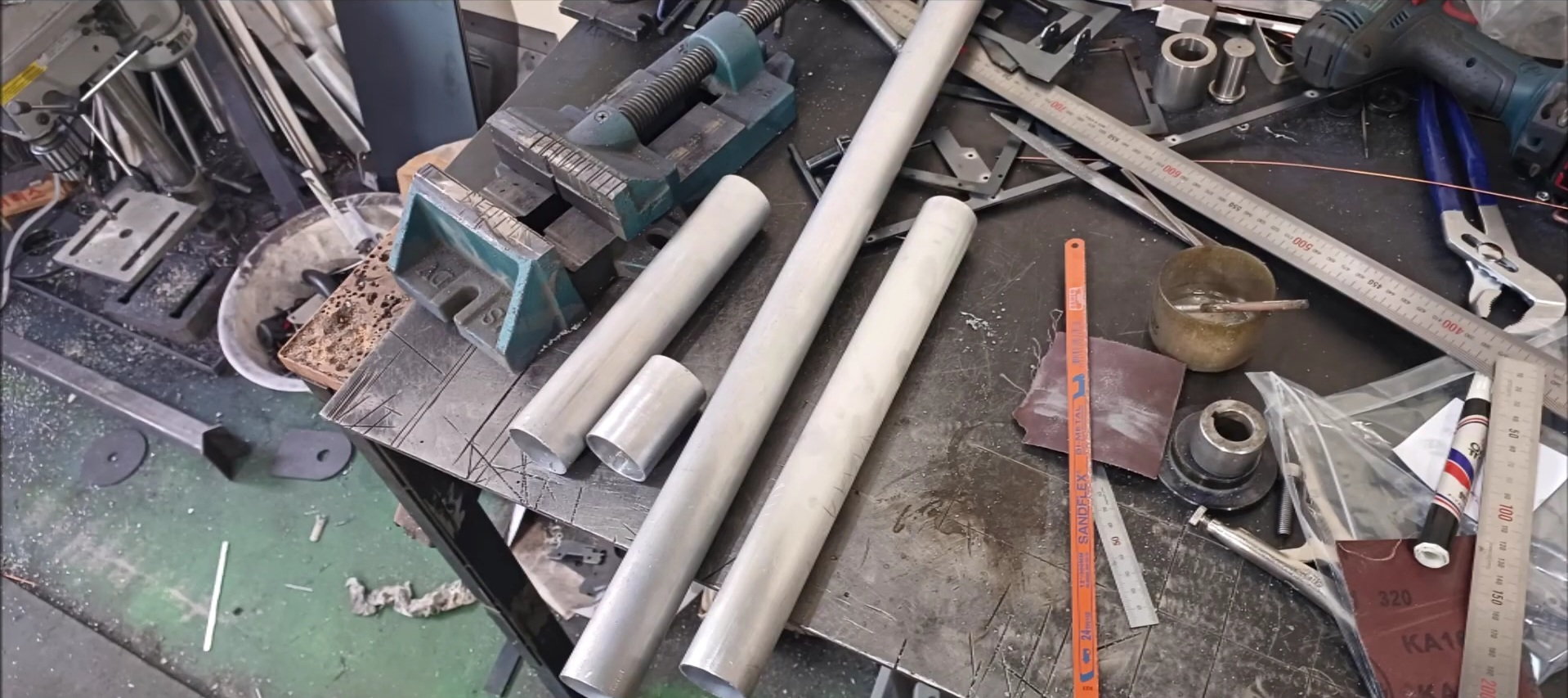
Cannon Pipe Processing
09-28-2023, 10:28 PM
#143
Thread Starter
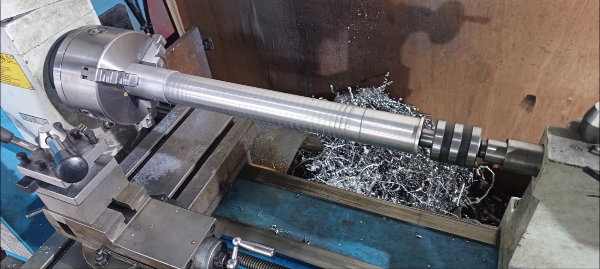
Surface machining of linear bearing connection
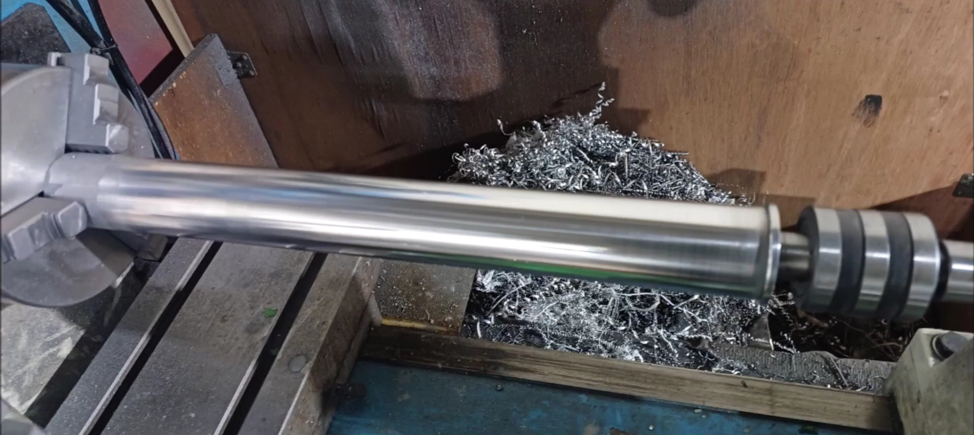
Surface machining of linear bearing connection
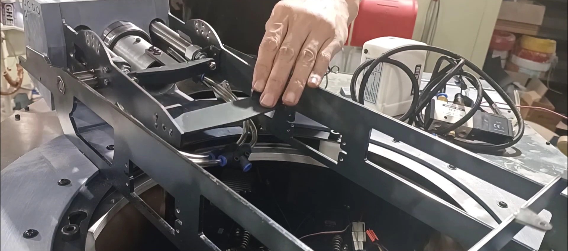
Recoil buffer operation test
Recoil buffer operation test
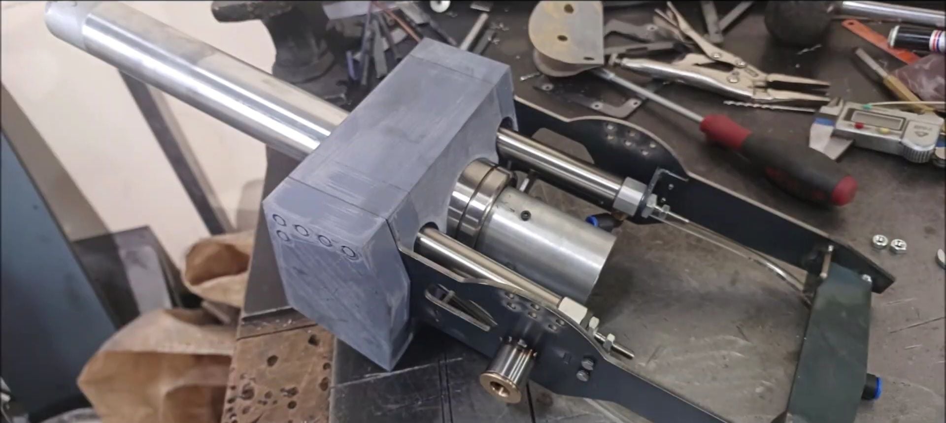
Installing the recoil buffer fixing pipe
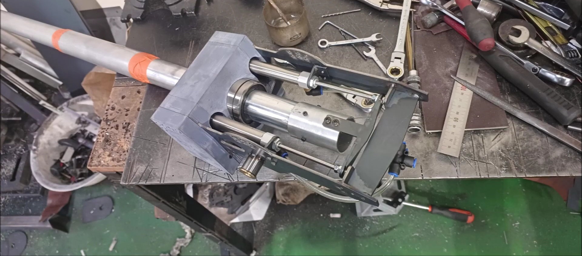
Check the travel distance between the air cylinder and the recoil buffer
Operation test of air cylinder and recoil buffer
Operation test of air cylinder and recoil buffer
Operation test of air cylinder and recoil buffer
Operation test of air cylinder and recoil buffer
Operation test of air cylinder and recoil buffer
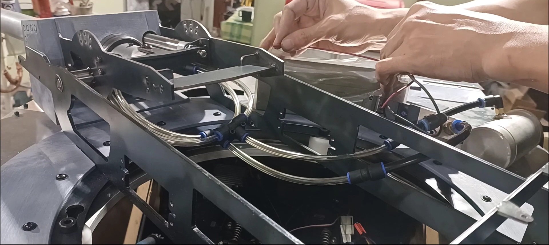
Operation test of air cylinder and recoil buffer
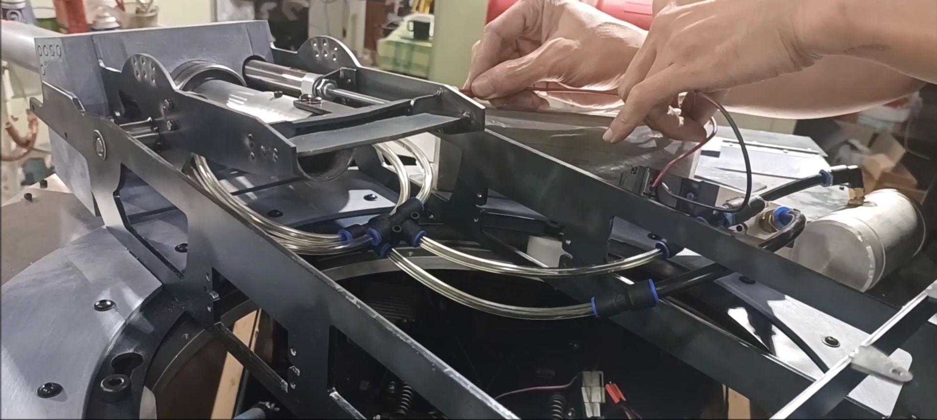
Operation test of air cylinder and recoil buffer (see previously uploaded video)
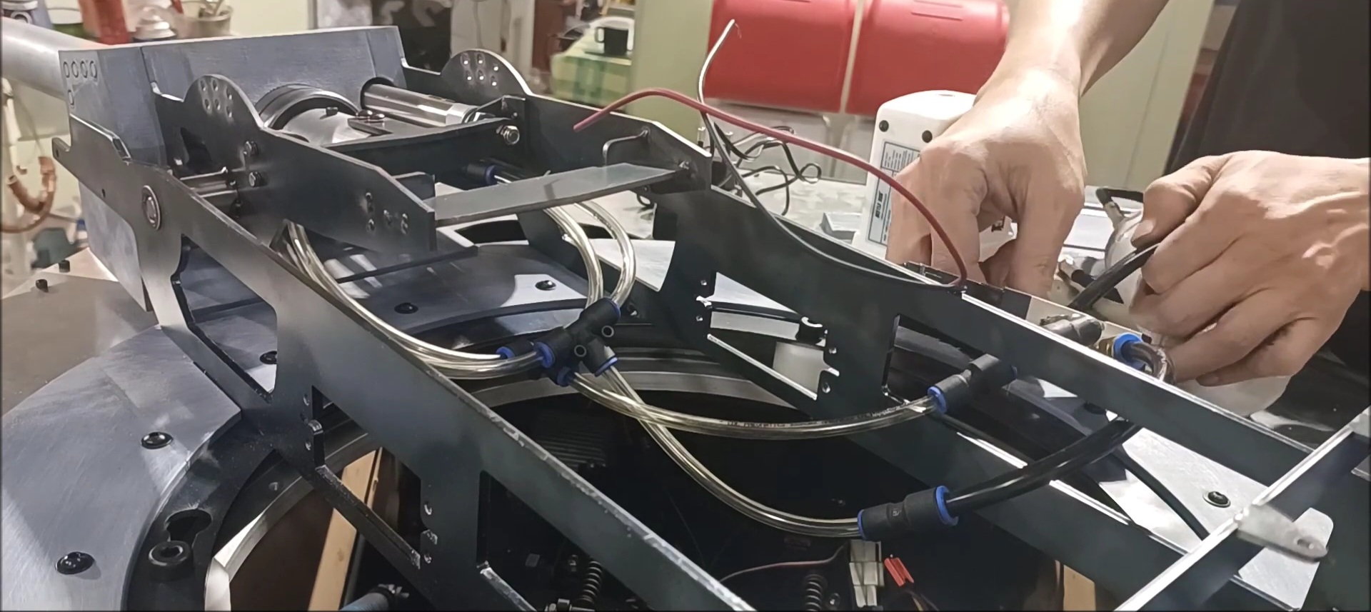
Recoil test
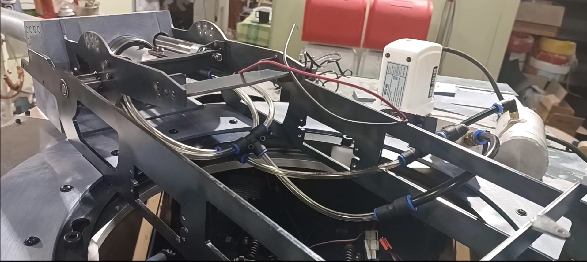
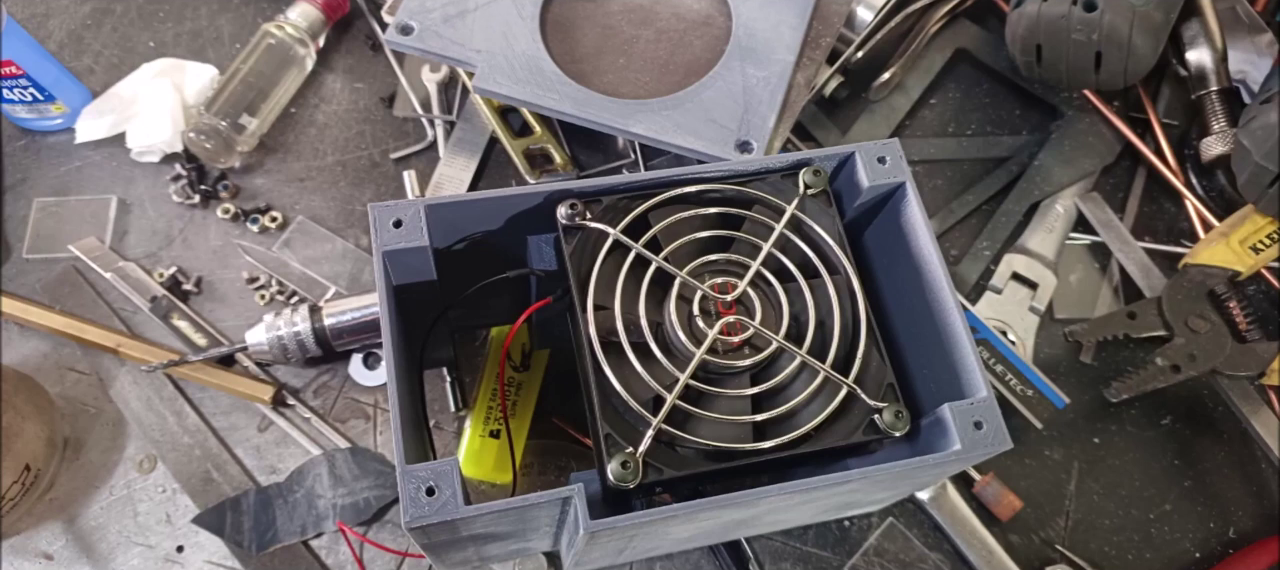
Recoil operation consisted of a small compressor, an air tank, and a solenoid valve.
Recoil test(see previously uploaded video)
Recoil test(see previously uploaded video)
Recoil test(see previously uploaded video)
The recoil operation was appropriate and the compressor position considering vibration will be configured on the turret inner structure.
The following users liked this post:
PE YOUNG (11-23-2023)
10-04-2023, 02:51 PM
#145
Only 7 months ago and so much has been done. Nice work!
The following users liked this post:
PE YOUNG (11-22-2023)
10-13-2023, 11:40 PM
#146
Thread Starter
The production of the work has been delayed due to the busy work.
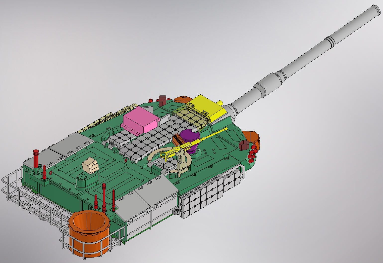
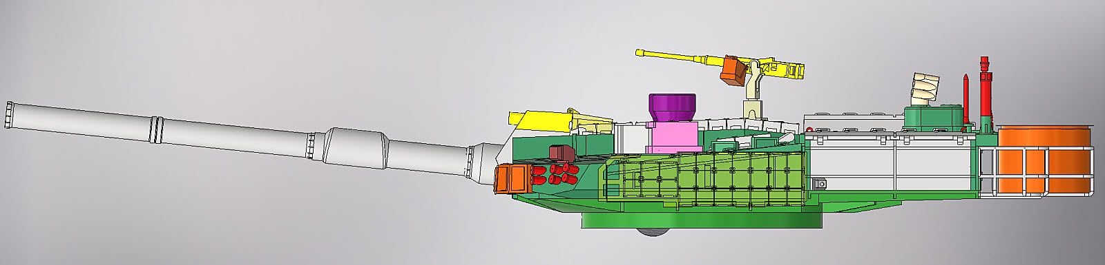
We produce the desert version based on the Korean standard turret design of the K2 Black Panther
This turret is manufactured to minimize weight considering engine power and body weight
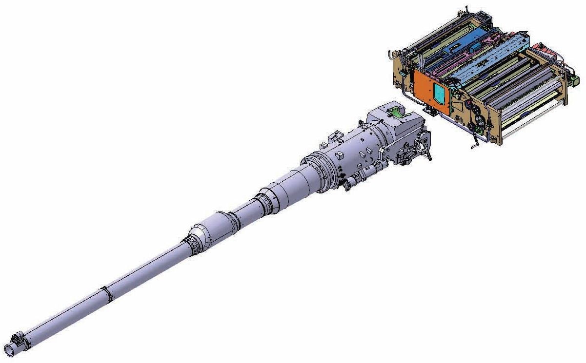
The main gun will be shaped similarly only to the outside
The main part of a turret's appearance
The main part of a turret's appearance
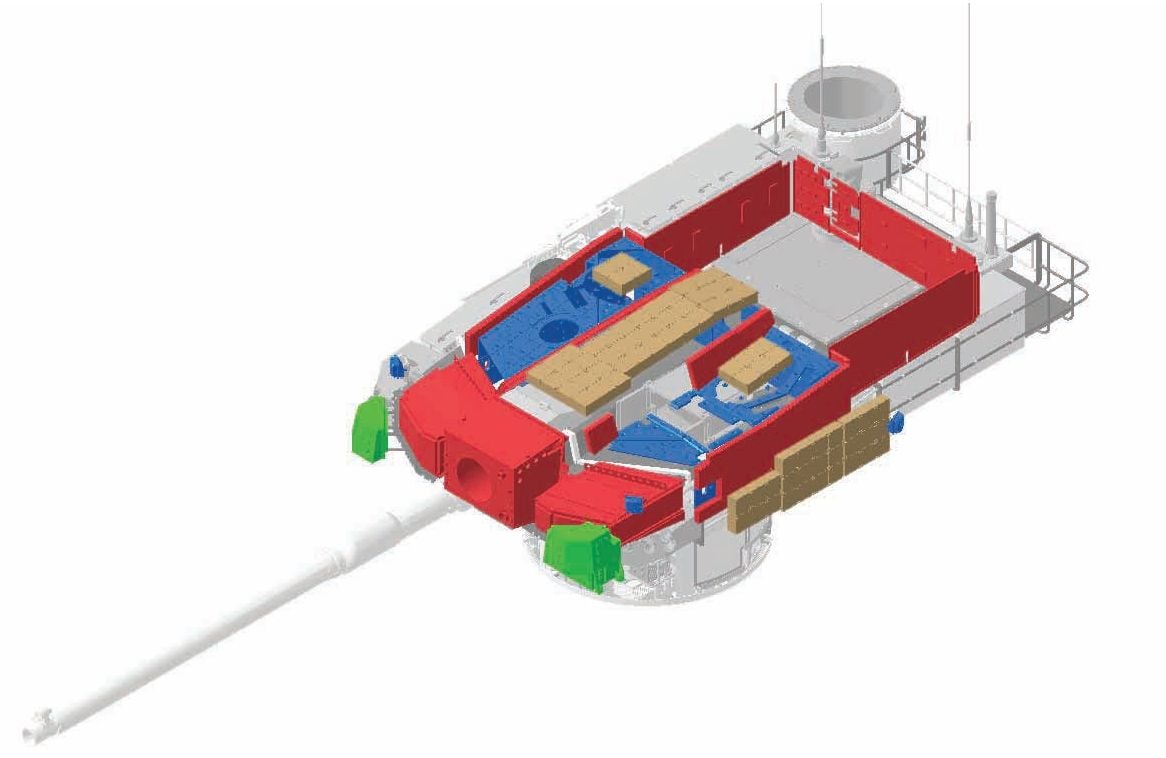
the lower part of the turret
the lower part of the turret
Non-Explosive Reactive Armor installed in the tank commander's hatch
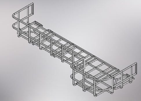
K2 Tank Rear Basket
K2 turret side defense NERA
K2 tank field sight
Tank shooter Hatch and Non-Explosive Reactive Armor
Tank gunner sight
K2 Military Wave Surveillance Radar

The turret's front view
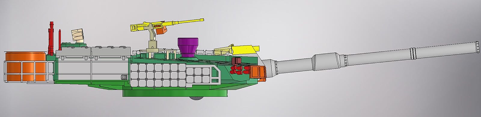
Left side view of turret
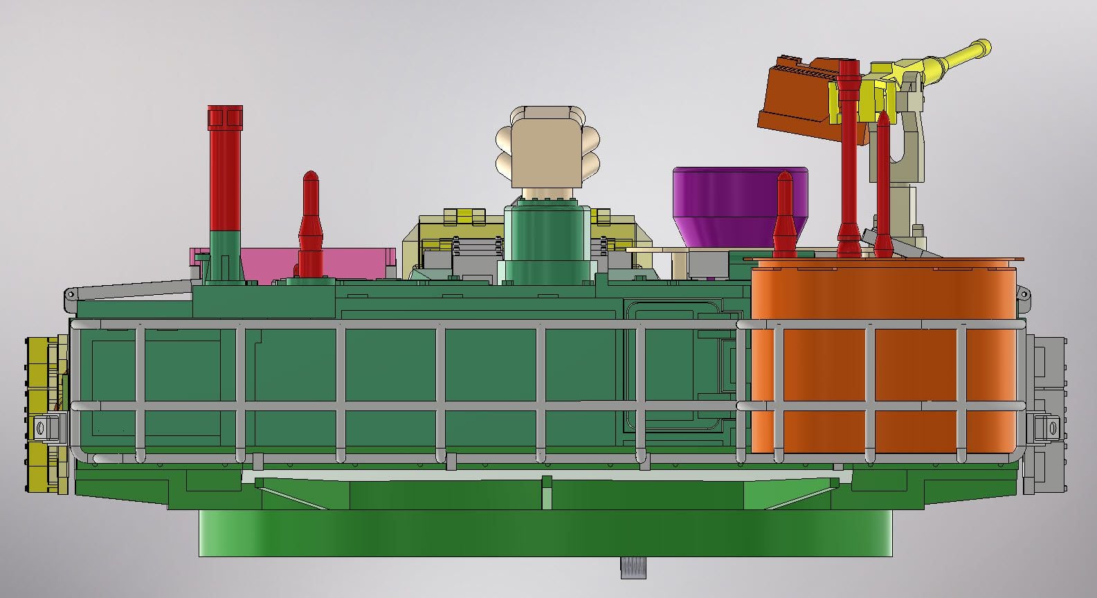
The back of the turret
Right side view of the turret
The shape of the turret will be made until next week

The progress is slow because it is 3D-printing to compensate for the problems that appeared during the production of the No. 1 K2 tank
Turret Front Structure Shape 3D Printing Production
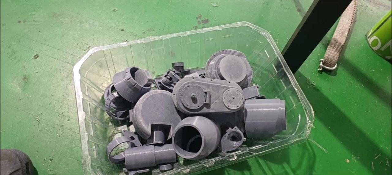
Parts to be used in turrets and main guns
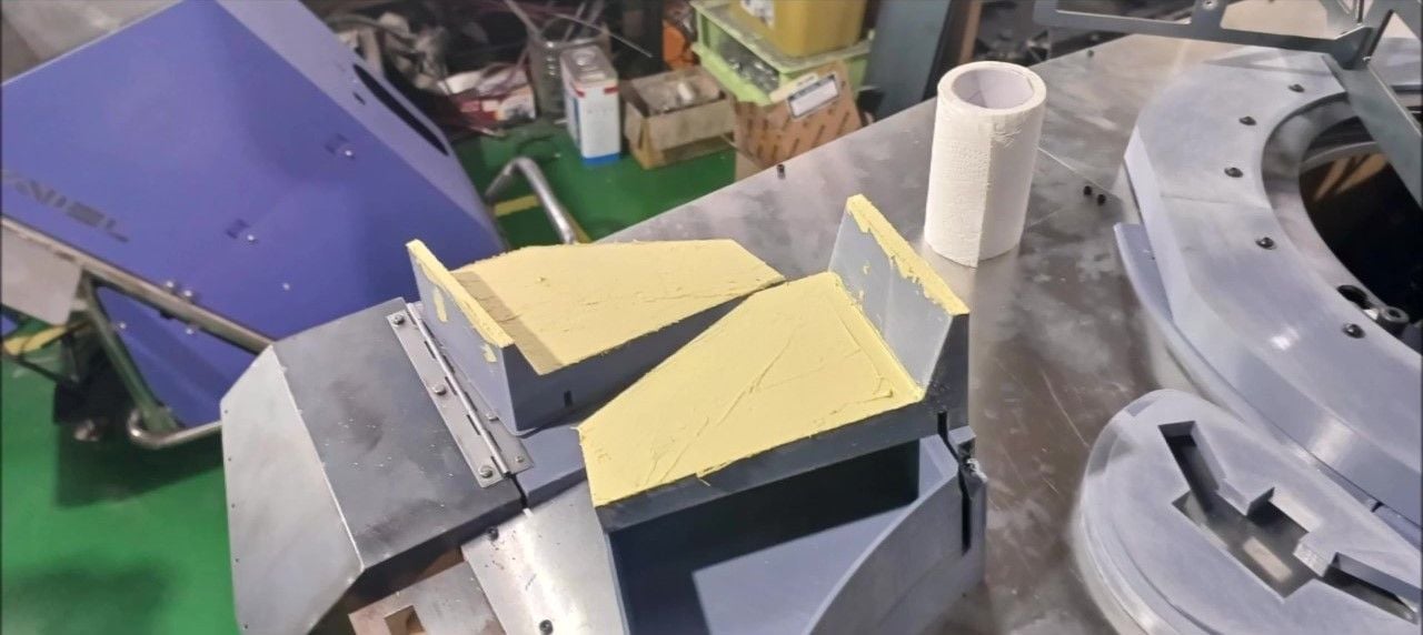
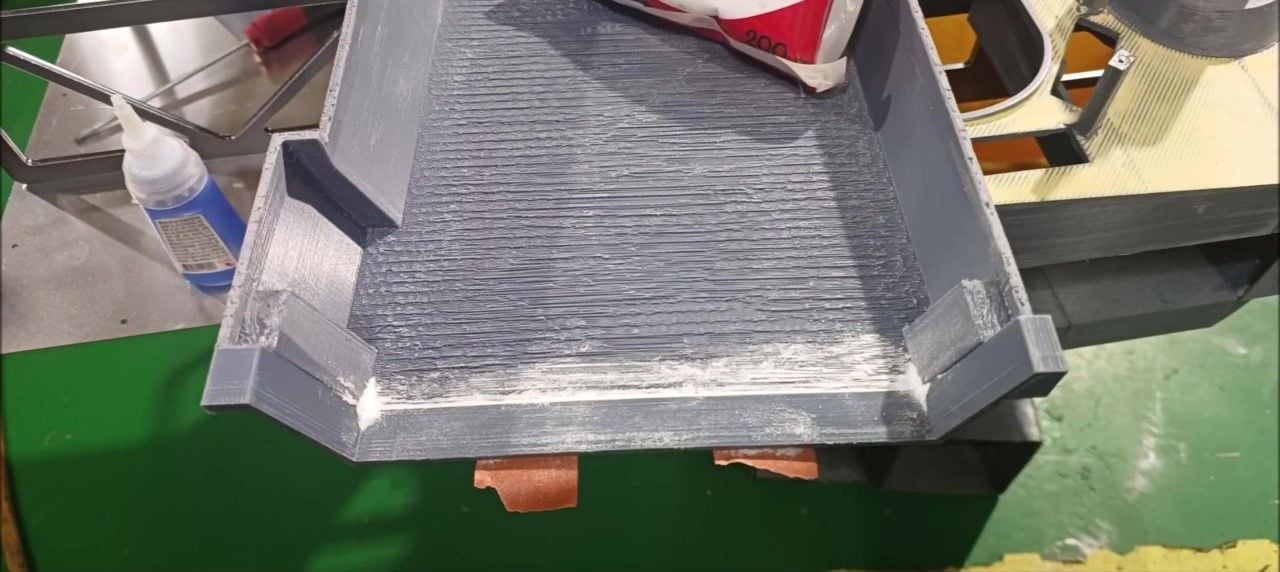
Added polyputty to smooth the plane
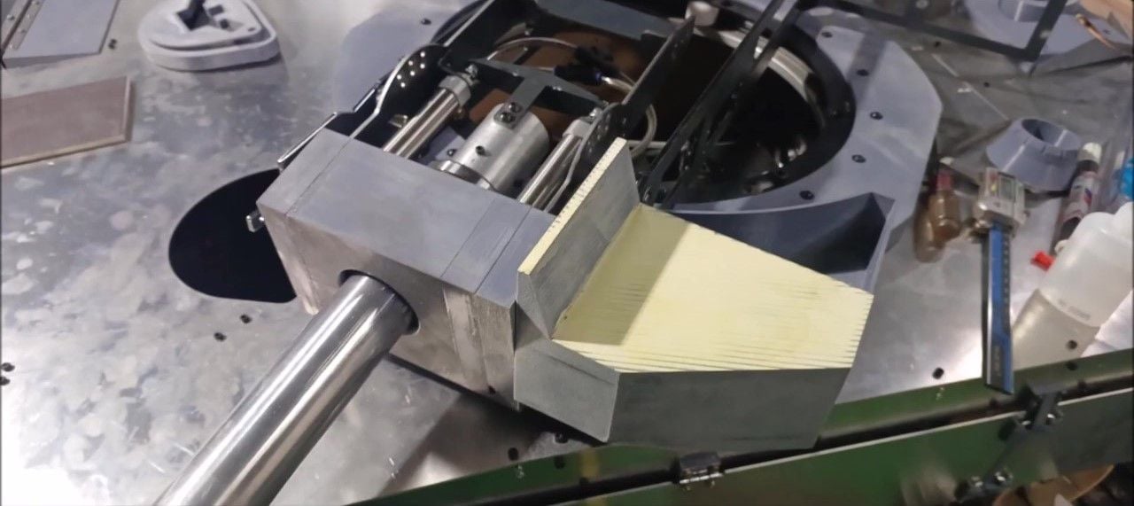
The appearance of sanding the polyputty
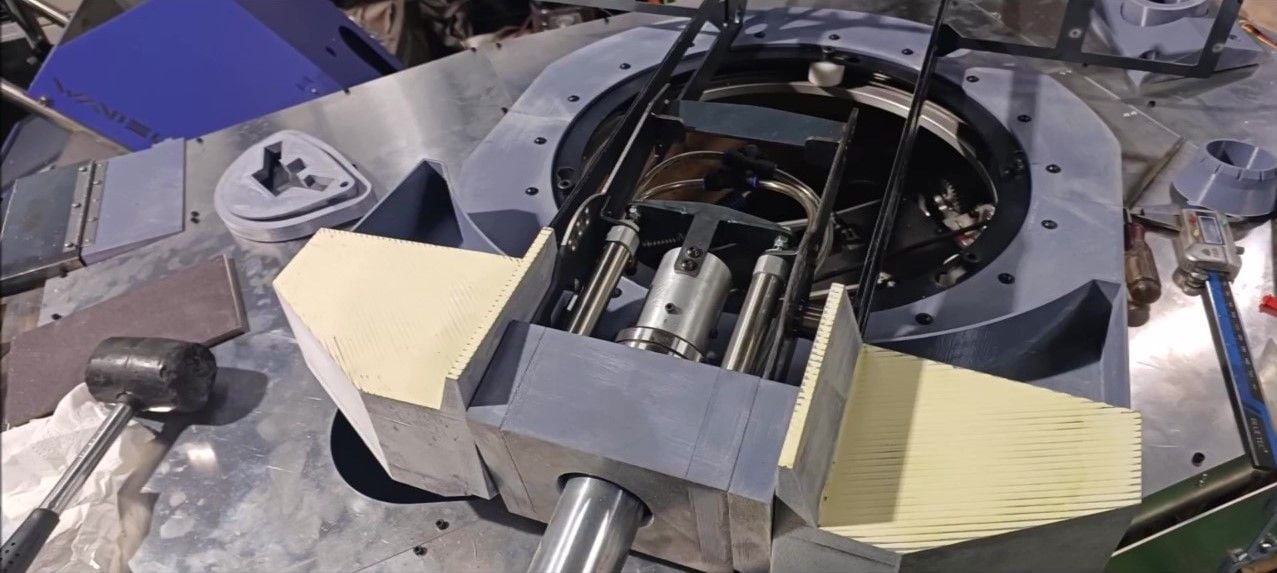
The appearance of sanding the polyputty
We produce the desert version based on the Korean standard turret design of the K2 Black Panther
This turret is manufactured to minimize weight considering engine power and body weight
The main gun will be shaped similarly only to the outside
The main part of a turret's appearance
The main part of a turret's appearance
the lower part of the turret
the lower part of the turret
Non-Explosive Reactive Armor installed in the tank commander's hatch
K2 Tank Rear Basket
K2 turret side defense NERA
K2 tank field sight
Tank shooter Hatch and Non-Explosive Reactive Armor
Tank gunner sight
K2 Military Wave Surveillance Radar
The turret's front view
Left side view of turret
The back of the turret
Right side view of the turret
The shape of the turret will be made until next week
The progress is slow because it is 3D-printing to compensate for the problems that appeared during the production of the No. 1 K2 tank
Turret Front Structure Shape 3D Printing Production
Parts to be used in turrets and main guns
Added polyputty to smooth the plane
The appearance of sanding the polyputty
The appearance of sanding the polyputty
Last edited by PE YOUNG; 10-14-2023 at 07:59 PM.
10-14-2023, 06:31 PM
#147
Thread Starter
3D output to reinforce turret rear lower plate
Aluminum sheet for turret rear lower plate
The turret's rear bottom plate is finished with aluminum sheets and 3D printed reinforcement
The turret's rear bottom plate is finished with aluminum sheets and 3D printed reinforcement
The turret rear lower plate is bolted to the internal structure
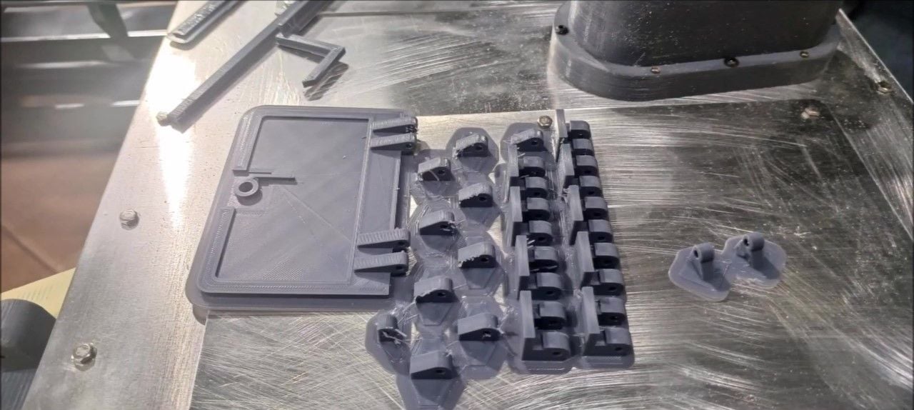
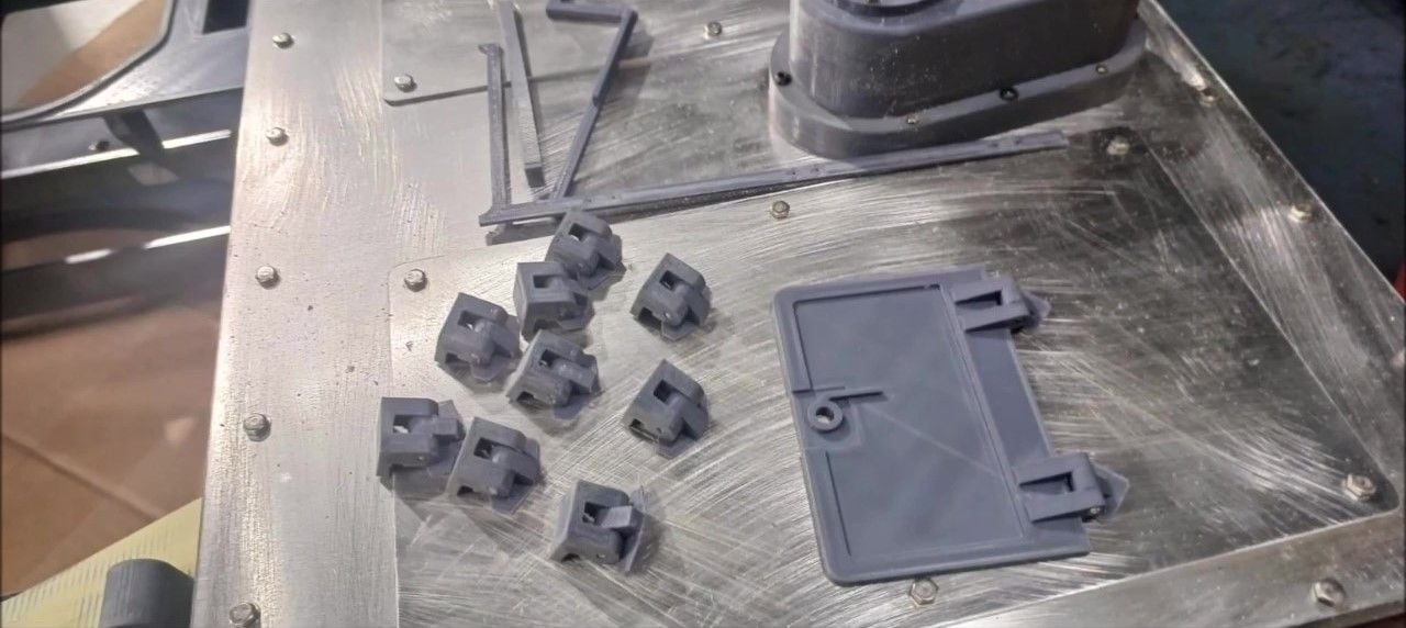
3D printer output from driver hatches and fixtures
Hatch fasteners and turreting front guards fitted to the front sheet
Hatch fastener and swing type hatch mechanism
Test the hatch fastener and swing-type hatch mechanism
Test the hatch fastener and swing-type hatch mechanism
Main gun shield and main gun connection closed
Secure clearance at main gun connections and main gun motion (protecting the root of the main gun)
The production of a main gun
Connecting the main gun to the Bore evaporator
Main gun to Bore evaporator (bolt hole blind)
Test the operation after connecting the main gun to the Bore evaporator
Test the operation after connecting the main gun to the Bore evaporator
Manufactured to detach the front of the main gun when moving the vehicle
Completing the shape of the main gun
Building a top plate on the left side of the top of the turret (including the polyperty work)
Building a top plate on the left side of the top of the turret (including the polyperty work)
Installation of turret upper plate fixing structure on steel structure
Attaching the front part of the turret to the lower rotating part of the turret (pictured on the right)
Attaching the front part of the turret to the lower rotating part of the turret
Completion of the configuration of the left front Gunner part of the turret
10-14-2023, 07:24 PM
#148
Thread Starter
Completion of the right front commander part structure of the turret
Completion of the main gun upper cover structure
Completion of the main gun upper cover structure
The main gun upper cover structure is made to be open and closed for normal care
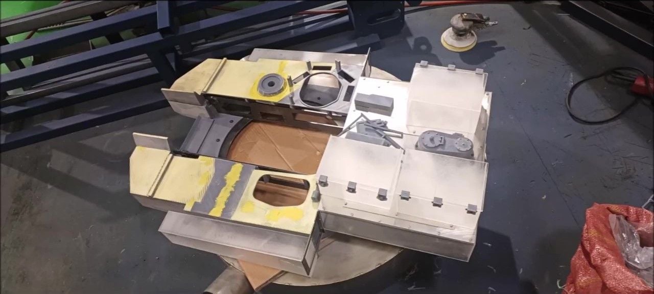
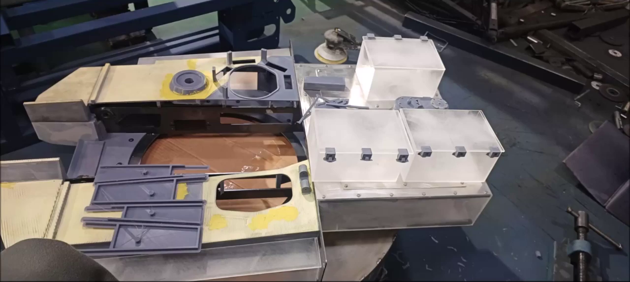
Production of turret shape is in progress
Production of turret shape is in progress
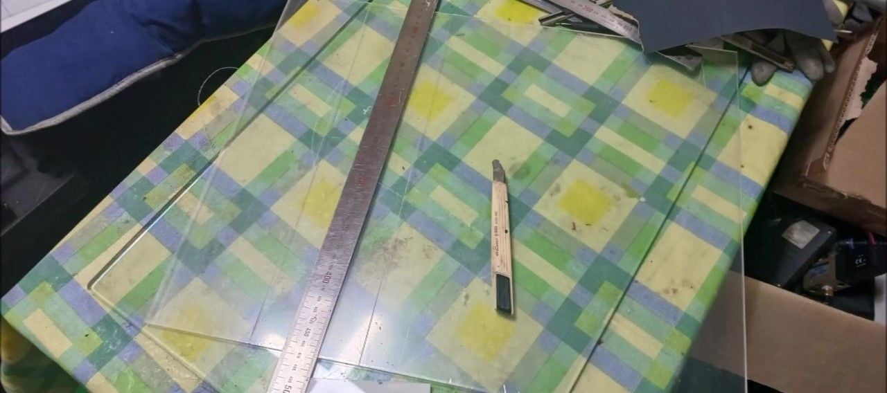
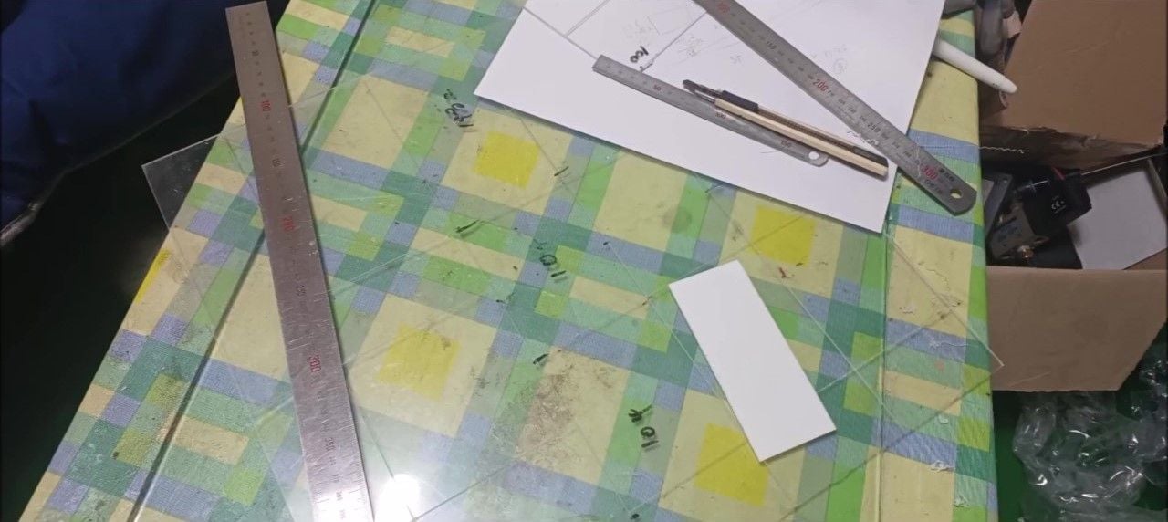
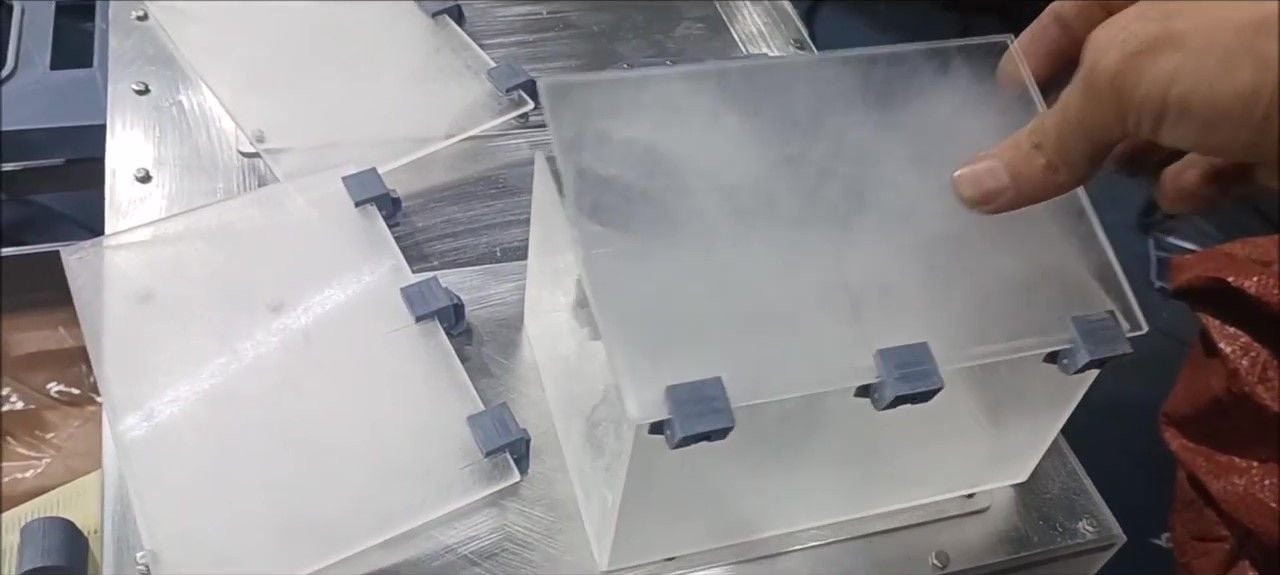
Simple flat plate is made of acrylic sheet to reduce weight
Production of the back of the turret
3D-printed output for fixing the turret rear storage box
Bolts the support bar to the lower plate of the support bar
Bolts the support bar to the lower plate of the support bar
Bolts the support bar to the lower plate of the support bar
Installation of shell storage top at the rear of the turret
Installation of shell storage acrylic side plates at the back of the turret
Installation of shell storage acrylic side plates at the back of the turret
Installation of the rear explosion guide top cover on the back of the turret
Install the softkill unit base in the center of the rear of the turret
Installing a Softkill Device
Fabrication of acrylic parts (side space box, periscope, etc.)
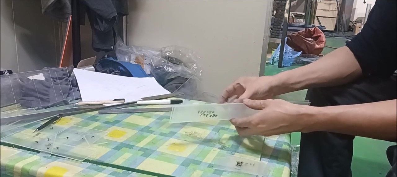
Fabrication of acrylic parts (side space box, periscope, etc.)
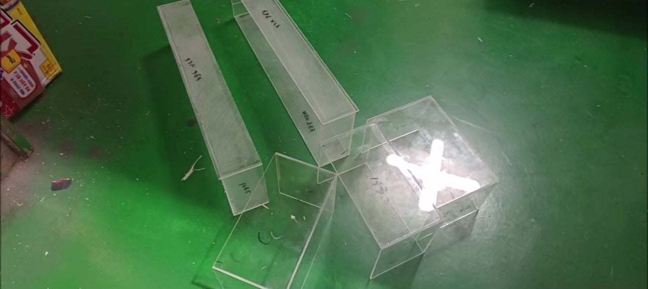
Acrylic parts fabrication - side space boxes, etc
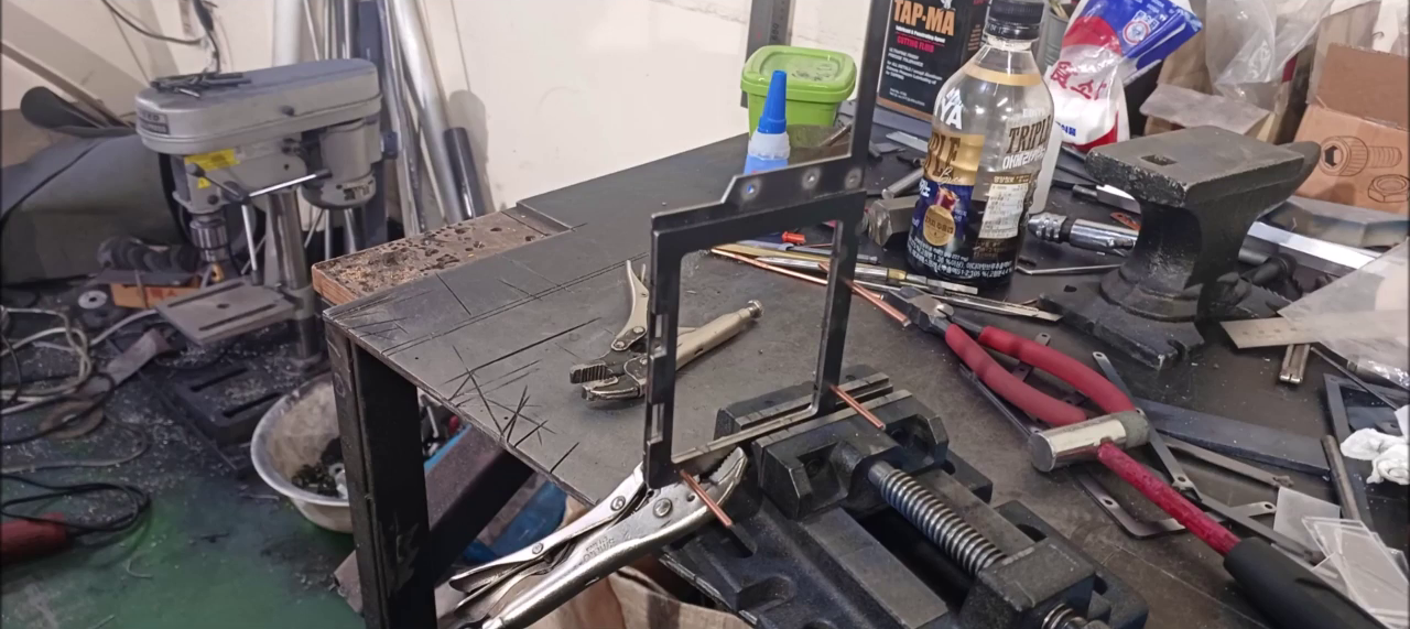
Fabrication of hinges for turret rear shell feed door and left right box
Fabrication of hinges for turret rear shell feed door and left right box
Turret rear plate shape complete (hole for shell feed)
Rear toolboxes (made of acrylics)
10-14-2023, 07:30 PM
#149
Thread Starter
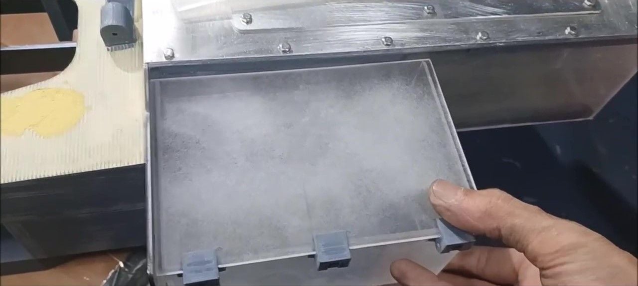
Turret rear side toolbox (made of acrylic)
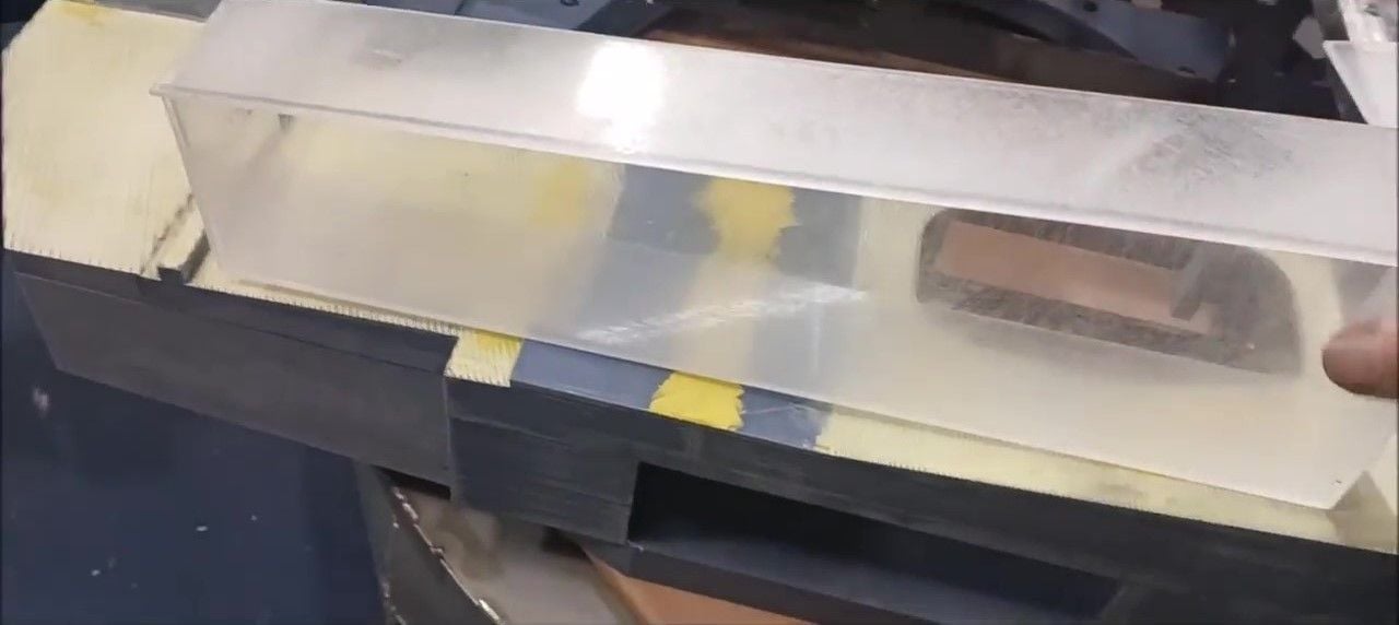
Turret Side Space Box (Production of Acrylic)
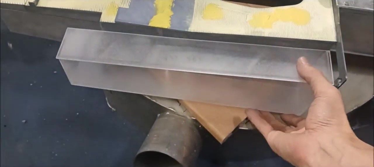
Turret Side Space Box (Production of Acrylic)
Turret left/right side space box (made of acrylic)
The turret production will be completed by next week, after completing electrical wiring work for headlights, signal lights, turret power supply and generator connection, various external details will be carried out, and finish painting before shipment, and this project will be completed.
And we will continue the upgrade process in the future by using the K2 desert version 1/5 scale RC tank completed in a separate thread.
For future upgrades, see
1. Engine Output 35CC -> 80CC Change
2. Change radio control mode (2 Stick -> 1 Stick Control)
3. Add main gun and turret stabilizer
4. Steel and metallization if plastic parts are required
5. This is a modified posture stabilizer, a feature of the K2 tank.
10-22-2023, 06:24 AM
#150
Thread Starter
This week, following last week, we continued to build turrets, and in the second half, we started wire connections.
Preparation for the installation of the 3 toolboxes on the rear
A frame for fixing the rear basket of the turret was constructed
A frame for fixing the rear basket was installed at the rear end of the turret
A side toolbox fixing frame was installed on the left side of the rear end of the turret
An intermediate frame for fixing the side toolbox was attached to the shell storage reservoir
Started installing toolbox
Two toolboxes on the left have been installed
Installation of 2 left toolboxes - Installation of fixture plates at the bottom
Installation of vertical frame for basket fixing on the back of the turret
Installation of shell feed doors and left and right antenna bases on the rear of the turret
Making panel parts for Teret Side Additional Reactive Armor installation
Integrated panel parts for Teret Side Reactive Armor installation
Secure panel for installation of Reactive Armor in front space box on left side of the terret
Hetch for Gunner Installation Completed
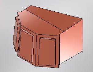
Manufacture of the right air conditioner outdoor unit
Vent installation on the right air conditioner outdoor unit connection
A toolbox and an outdoor unit were installed on the right rear side
1 toolbox, outdoor unit and front space box installed on the right side of the turret
Accessories such as smoke launchers and radar sensors to be installed on the terret have been manufactured
Performing polyputty work on the smoke launcher assembly
Dynamic Detection Sensor and Identification Friend or Foe Manufactured
Fabrication of the upper unit of the cannon shield completed
Installation of turret front radar and smoke bomb launcher
Turret front radar and smoke bomb launcher installed
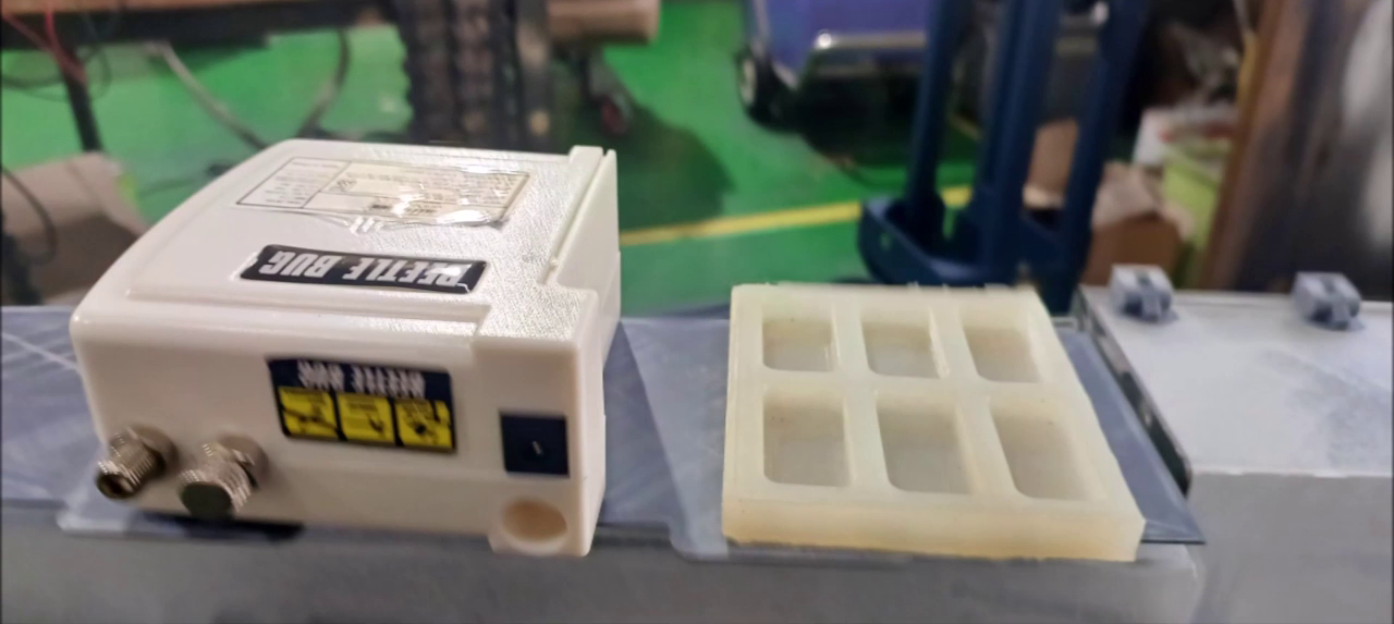
Air compressor and anti-vibration silicon pad
Preparation for the installation of the 3 toolboxes on the rear
A frame for fixing the rear basket of the turret was constructed
A frame for fixing the rear basket was installed at the rear end of the turret
A side toolbox fixing frame was installed on the left side of the rear end of the turret
An intermediate frame for fixing the side toolbox was attached to the shell storage reservoir
Started installing toolbox
Two toolboxes on the left have been installed
Installation of 2 left toolboxes - Installation of fixture plates at the bottom
Installation of vertical frame for basket fixing on the back of the turret
Installation of shell feed doors and left and right antenna bases on the rear of the turret
Making panel parts for Teret Side Additional Reactive Armor installation
Integrated panel parts for Teret Side Reactive Armor installation
Secure panel for installation of Reactive Armor in front space box on left side of the terret
Hetch for Gunner Installation Completed
Manufacture of the right air conditioner outdoor unit
Vent installation on the right air conditioner outdoor unit connection
A toolbox and an outdoor unit were installed on the right rear side
1 toolbox, outdoor unit and front space box installed on the right side of the turret
Accessories such as smoke launchers and radar sensors to be installed on the terret have been manufactured
Performing polyputty work on the smoke launcher assembly
Dynamic Detection Sensor and Identification Friend or Foe Manufactured
Fabrication of the upper unit of the cannon shield completed
Installation of turret front radar and smoke bomb launcher
Turret front radar and smoke bomb launcher installed
Air compressor and anti-vibration silicon pad