


Foam Core wing retract install
 03-25-2011, 02:33 PM
#1

Thread Starter
Hello all,
Throughout the years all I've ever done was construct built up wings and I am unfamiliar with installing retracts in foam core wings. I will be starting a Jemco hellcat and possibly a P47 and could use some ideas. I understand there was supposed to be a additional set of instructions with the Hellcat for the retract install but my kit didn't have them in it. Does anyone have a copy of those?
Thanks in advance,
Ted

 03-25-2011, 03:15 PM
#3

ORIGINAL: chistech
Hello all,
Throughout the years all I've ever done was construct built up wings and I am unfamiliar with installing retracts in foam core wings. I will be starting a Jemco hellcat and possibly a P47 and could use some ideas. I understand there was supposed to be a additional set of instructions with the Hellcat for the retract install but my kit didn't have them in it. Does anyone have a copy of those?
Thanks in advance,
Ted

My method differs a little from the previous post. I like to spread the load over a greater area by adding a hardwood sq stock to the mounting blocks running parallel to the cord to the leading edge, and a couple inches aft of the gear. This spreads the torque force out, in the event of a hard strike to the mains. This is cut into the foam and flush with the surface, then sheeted over. Very strong.
03-25-2011, 04:11 PM
#5
ORIGINAL: DAN REISS
Gary, That sounds interesting. Please post some images if you have them. Dan.
Gary, That sounds interesting. Please post some images if you have them. Dan.
03-25-2011, 04:20 PM
#6


Join Date: Mar 2002
Location: Smithfield,, VA
Posts: 1,013
Likes: 0
Received 0 Likes
on
0 Posts
Hi guys,
Both posts regarding the retract installiation in foam core wings will no doubt work. I have to agree with Gary in the need to spread out the loads to abosrb the torque to the rear in a hard landing. I'm sure the box installiation will work just fine on most normal landings, but it appears to me that the loads of a hard landing will be mostly shear between the vertical walls of the box and the foam and against the top skin.
Last year I finished my Yellow Aircraft P-47. I was concerned about the load distribution in the foam core and did a major modification of the gear mounting pads to increase the affected area as much as I could. You can see this in my build at the following site. Comments welcome.
Dash
http://www.rcuniverse.com/forum/m_8836329/tm.htm
03-25-2011, 04:26 PM
#7
Yes, another method I have used is to use ply to make ribs fore and aft of the 'box', and epoxy these into slots in the foam, and to the 'box', prior to sheeting. This gives the box no where to go, and virtually makes it impossible to twist it out of the wing. The foam, by itself, just can't give enough support to prevent this from happening, if the unspeakable occurs.
03-25-2011, 05:01 PM
#8
My Feedback: (102)
Here are my videos showing one way to do it....
http://www.youtube.com/watch?v=H66GwhIL5P4
http://www.youtube.com/watch?v=JEfBNuGatHQ
Ty
http://www.youtube.com/watch?v=H66GwhIL5P4
http://www.youtube.com/watch?v=JEfBNuGatHQ
Ty
03-25-2011, 05:09 PM
#9
Dash, Thanks for that thread. It will help me during my next build. I have switched from epoxy thickened with micro balloons to secure my plywood box to Gorilla glue since I was never able to get a good fit. It bonds great to the plywood and foam and does not need to be any stronger than the foam since the whole wing is foam. My method has survived some very bad landings with no damage. During the really terrible landings, the half inch Robart strut will bend and the box stays intact. During the controlled crashes, the strut bends, the gear gets distorted and the box breaks with damage to the top wing skin, etc.. It is not too much work to cut out the damaged box and replace it with a new one using a lot of Gorilla glue. And of course, the repair to the wing. But, I would survive better if the force was spread some more over the bottom of the foam. I like your method and may use a plate similar to yours that is secured to my type of plywood box. Dan.
03-25-2011, 05:13 PM
#10
These are great videos. All I would do different is to make the ends of the box oversize in length to spread that torque load over more of the foam area. Here again, this only takes a slice in the foam the thickness of the ply, and epoxy. It would also be the contour of the foam top and bottom.
A good whack could twist out what you see, IMO.
A good whack could twist out what you see, IMO.
03-25-2011, 05:18 PM
#12
My Feedback: (102)
Thanks Guys,
I did not show it but I usually cut the ribs back further into the wing to carry the load over a bigger area. But i have not ever torn the gear out even as small as this area is. you would really have to slam it down to break it out...
Ty
I did not show it but I usually cut the ribs back further into the wing to carry the load over a bigger area. But i have not ever torn the gear out even as small as this area is. you would really have to slam it down to break it out...
Ty
03-25-2011, 08:35 PM
#13
My Feedback: (2)
Join Date: Feb 2002
Location: Orange,
NJ
Posts: 1,334
Likes: 0
Received 0 Likes
on
0 Posts
Yes Chistech watch TYs videos, that man can build his ***** off. He has some very good stuff on youtube. You cant go wrong with his method especially with using glass cloth beneath the wing skins.
03-25-2011, 08:50 PM
#14
ORIGINAL: fockewulf37
Thanks Guys,
I did not show it but I usually cut the ribs back further into the wing to carry the load over a bigger area. But i have not ever torn the gear out even as small as this area is. you would really have to slam it down to break it out...
Ty
Thanks Guys,
I did not show it but I usually cut the ribs back further into the wing to carry the load over a bigger area. But i have not ever torn the gear out even as small as this area is. you would really have to slam it down to break it out...
Ty
03-25-2011, 11:06 PM
#15
Senior Member
My Feedback: (1)
Join Date: Feb 2004
Location: Nevada City ,
CA
Posts: 602
Likes: 0
Received 0 Likes
on
0 Posts
I am working on a Jemco P-47, and I have been scratching my head about the retract install. This will be my first foam core wing. The p-47 gear retracts inward, but also somewhat aft. When extended, the legs lean down and Forward... How does one go about figuring out what angle to install the mounts in the foam so that the gear will operate in the right way, and the wheel will end up straight when extended, and flush with the wing when retracted?
03-26-2011, 04:38 AM
#16
ORIGINAL: BadSplice
I am working on a Jemco P-47, and I have been scratching my head about the retract install. This will be my first foam core wing. The p-47 gear retracts inward, but also somewhat aft. When extended, the legs lean down and Forward... How does one go about figuring out what angle to install the mounts in the foam so that the gear will operate in the right way, and the wheel will end up straight when extended, and flush with the wing when retracted?
I am working on a Jemco P-47, and I have been scratching my head about the retract install. This will be my first foam core wing. The p-47 gear retracts inward, but also somewhat aft. When extended, the legs lean down and Forward... How does one go about figuring out what angle to install the mounts in the foam so that the gear will operate in the right way, and the wheel will end up straight when extended, and flush with the wing when retracted?


 03-26-2011, 10:35 AM
#20
Now for the boring words, since i have some time to write them 
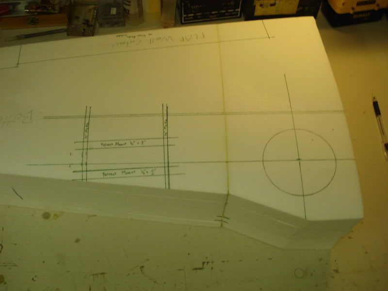
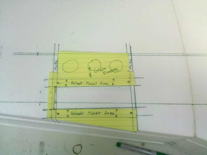
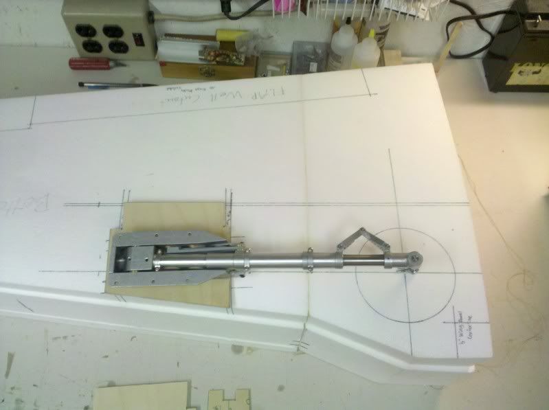
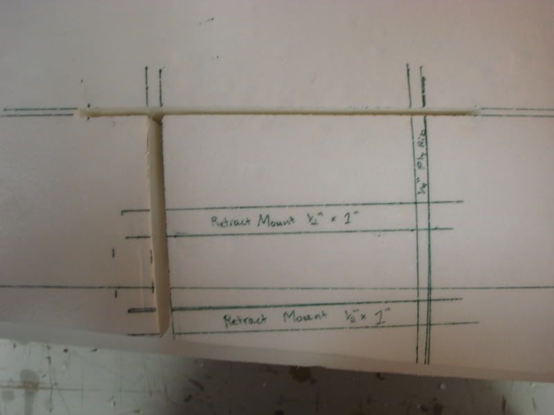
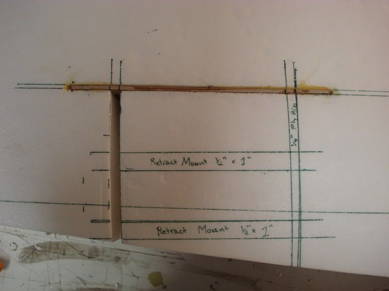
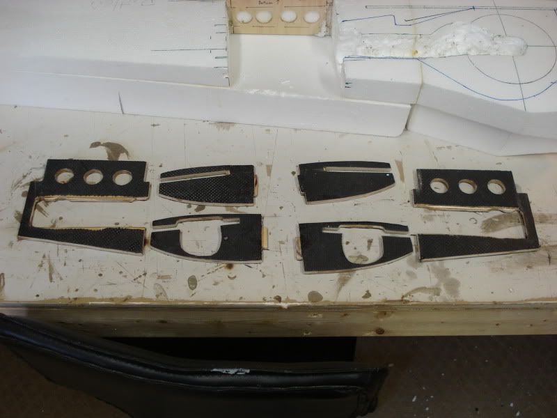
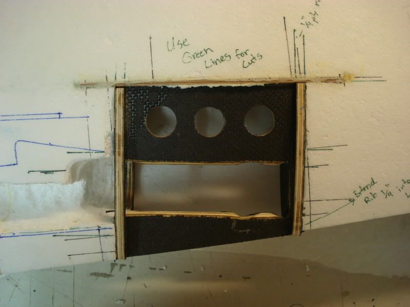
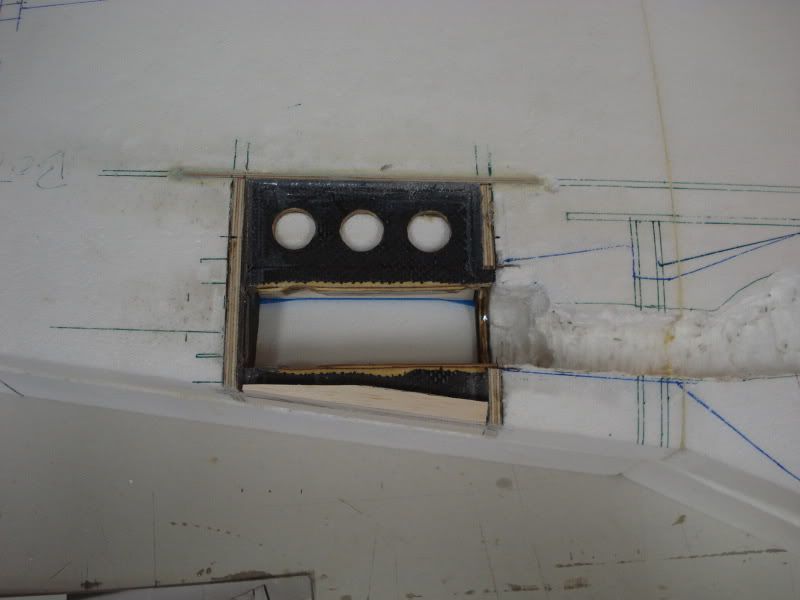
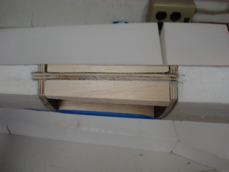
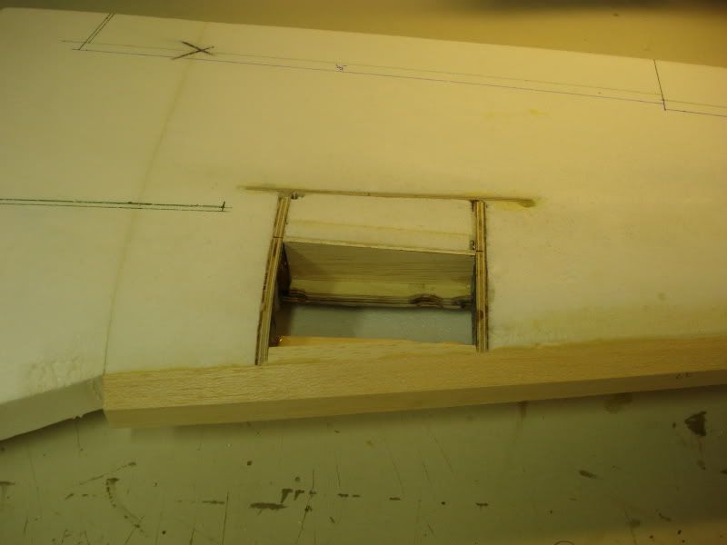
All of the ribs and gear plate are 1/4" 5-ply aircraft plywood. They are laminated w/ 1 layer of 3k carbon cloth on each side w/ each layer of cloth oriented 45* to the other. The ribs are notched to fit into the semi-spar, and the gear-plate slides into place in the slots in the false ribs.
The Gear plate has an additional piece of 1/4" thick x 1/2" wide aircraft ply doubler in the area of the landing gear bolts.
the Plywood "semi-spar" that runs the parallel to the span of the wing is 1/8" 5-ply aircraft ply w/ lightening holes cut into it and rests roughly 1/8" below the surface on the top and bottom.
I replaced as much of the foam core that was removed back into the wing before it was sheeted. I used Hysol to glue the wood parts to each other, and Gorilla Poly-U glue to glue the wood parts to the foam. the Wing also had the leading edge installed BEFORE sheeting the wing. the reason for this, is I designed the gear structure to use the leading edge as part of it. So in order for the forward mount to transfer stress to the leading edge and the LE to transfer stress to the rest of the wing, the sheeting was placed over the leading edge, so the LE is sandwiched by the wing skins and the skins transfer the load to the rest of the wing from the LE.
The only thing i would do different, is make the gear plate approximately 1" longer in span that what is shown in the photo's and move the outboard false rib out with it as well.
03-26-2011, 10:50 AM
#21
Thread Starter
Man, you guys are the bomb! I'm glad I asked. I kind of thought that would be the way to install but I wanted to listen to others tried and tested techniques. I will be starting after I get done with an older Nick Z designed 50 sized P-47 all balsa job. I'm hoping to get three planes all built so my buddy can paint all at the same time. Thanks for the info and keep it coming. Got to love these forums.
Ted
I'm glad I asked. I kind of thought that would be the way to install but I wanted to listen to others tried and tested techniques. I will be starting after I get done with an older Nick Z designed 50 sized P-47 all balsa job. I'm hoping to get three planes all built so my buddy can paint all at the same time. Thanks for the info and keep it coming. Got to love these forums.Ted
03-26-2011, 02:52 PM
#22
ORIGINAL: invertmast
Now for the boring words, since i have some time to write them
All of the ribs and gear plate are 1/4'' 5-ply aircraft plywood. They are laminated w/ 1 layer of 3k carbon cloth on each side w/ each layer of cloth oriented 45* to the other. The ribs are notched to fit into the semi-spar, and the gear-plate slides into place in the slots in the false ribs.
The Gear plate has an additional piece of 1/4'' thick x 1/2'' wide aircraft ply doubler in the area of the landing gear bolts.
the Plywood ''semi-spar'' that runs the parallel to the span of the wing is 1/8'' 5-ply aircraft ply w/ lightening holes cut into it and rests roughly 1/8'' below the surface on the top and bottom.
I replaced as much of the foam core that was removed back into the wing before it was sheeted. I used Hysol to glue the wood parts to each other, and Gorilla Poly-U glue to glue the wood parts to the foam. the Wing also had the leading edge installed BEFORE sheeting the wing. the reason for this, is I designed the gear structure to use the leading edge as part of it. So in order for the forward mount to transfer stress to the leading edge and the LE to transfer stress to the rest of the wing, the sheeting was placed over the leading edge, so the LE is sandwiched by the wing skins and the skins transfer the load to the rest of the wing from the LE.
The only thing i would do different, is make the gear plate approximately 1'' longer in span that what is shown in the photo's and move the outboard false rib out with it as well.
03-26-2011, 03:13 PM
#23
ORIGINAL: ram3500-RCU
Nice description pal. Don't see anyone having problems after all this. The only tricky part is getting the angle and cant correct. Some trial and error is sometimes needed for this, if you don't have detailed plans.
ORIGINAL: invertmast
Now for the boring words, since i have some time to write them
All of the ribs and gear plate are 1/4'' 5-ply aircraft plywood. They are laminated w/ 1 layer of 3k carbon cloth on each side w/ each layer of cloth oriented 45* to the other. The ribs are notched to fit into the semi-spar, and the gear-plate slides into place in the slots in the false ribs.
The Gear plate has an additional piece of 1/4'' thick x 1/2'' wide aircraft ply doubler in the area of the landing gear bolts.
the Plywood ''semi-spar'' that runs the parallel to the span of the wing is 1/8'' 5-ply aircraft ply w/ lightening holes cut into it and rests roughly 1/8'' below the surface on the top and bottom.
I replaced as much of the foam core that was removed back into the wing before it was sheeted. I used Hysol to glue the wood parts to each other, and Gorilla Poly-U glue to glue the wood parts to the foam. the Wing also had the leading edge installed BEFORE sheeting the wing. the reason for this, is I designed the gear structure to use the leading edge as part of it. So in order for the forward mount to transfer stress to the leading edge and the LE to transfer stress to the rest of the wing, the sheeting was placed over the leading edge, so the LE is sandwiched by the wing skins and the skins transfer the load to the rest of the wing from the LE.
The only thing i would do different, is make the gear plate approximately 1'' longer in span that what is shown in the photo's and move the outboard false rib out with it as well.
Now for the boring words, since i have some time to write them
All of the ribs and gear plate are 1/4'' 5-ply aircraft plywood. They are laminated w/ 1 layer of 3k carbon cloth on each side w/ each layer of cloth oriented 45* to the other. The ribs are notched to fit into the semi-spar, and the gear-plate slides into place in the slots in the false ribs.
The Gear plate has an additional piece of 1/4'' thick x 1/2'' wide aircraft ply doubler in the area of the landing gear bolts.
the Plywood ''semi-spar'' that runs the parallel to the span of the wing is 1/8'' 5-ply aircraft ply w/ lightening holes cut into it and rests roughly 1/8'' below the surface on the top and bottom.
I replaced as much of the foam core that was removed back into the wing before it was sheeted. I used Hysol to glue the wood parts to each other, and Gorilla Poly-U glue to glue the wood parts to the foam. the Wing also had the leading edge installed BEFORE sheeting the wing. the reason for this, is I designed the gear structure to use the leading edge as part of it. So in order for the forward mount to transfer stress to the leading edge and the LE to transfer stress to the rest of the wing, the sheeting was placed over the leading edge, so the LE is sandwiched by the wing skins and the skins transfer the load to the rest of the wing from the LE.
The only thing i would do different, is make the gear plate approximately 1'' longer in span that what is shown in the photo's and move the outboard false rib out with it as well.
You aren't lying with that one my friend! Especially when it comes to a FW-190, or any of those other odd landing gear jobbies (spitfire, ME109, etc). Luckily the plans for my short-kit had the dimensions for where the rail should be from the wing skin, and how far from the trailing edge the axle should be. Unfortunately, most plans that i have seen do not do such a nice job of making the builders life easy.
03-26-2011, 03:23 PM
#24
ORIGINAL: invertmast
You aren't lying with that one my friend! Especially when it comes to a FW-190, or any of those other odd landing gear jobbies (spitfire, ME109, etc). Luckily the plans for my short-kit had the dimensions for where the rail should be from the wing skin, and how far from the trailing edge the axle should be. Unfortunately, most plans that i have seen do not do such a nice job of making the builders life easy.
ORIGINAL: ram3500-RCU
Nice description pal. Don't see anyone having problems after all this. The only tricky part is getting the angle and cant correct. Some trial and error is sometimes needed for this, if you don't have detailed plans.
ORIGINAL: invertmast
Now for the boring words, since i have some time to write them
All of the ribs and gear plate are 1/4'' 5-ply aircraft plywood. They are laminated w/ 1 layer of 3k carbon cloth on each side w/ each layer of cloth oriented 45* to the other. The ribs are notched to fit into the semi-spar, and the gear-plate slides into place in the slots in the false ribs.
The Gear plate has an additional piece of 1/4'' thick x 1/2'' wide aircraft ply doubler in the area of the landing gear bolts.
the Plywood ''semi-spar'' that runs the parallel to the span of the wing is 1/8'' 5-ply aircraft ply w/ lightening holes cut into it and rests roughly 1/8'' below the surface on the top and bottom.
I replaced as much of the foam core that was removed back into the wing before it was sheeted. I used Hysol to glue the wood parts to each other, and Gorilla Poly-U glue to glue the wood parts to the foam. the Wing also had the leading edge installed BEFORE sheeting the wing. the reason for this, is I designed the gear structure to use the leading edge as part of it. So in order for the forward mount to transfer stress to the leading edge and the LE to transfer stress to the rest of the wing, the sheeting was placed over the leading edge, so the LE is sandwiched by the wing skins and the skins transfer the load to the rest of the wing from the LE.
The only thing i would do different, is make the gear plate approximately 1'' longer in span that what is shown in the photo's and move the outboard false rib out with it as well.
Now for the boring words, since i have some time to write them
All of the ribs and gear plate are 1/4'' 5-ply aircraft plywood. They are laminated w/ 1 layer of 3k carbon cloth on each side w/ each layer of cloth oriented 45* to the other. The ribs are notched to fit into the semi-spar, and the gear-plate slides into place in the slots in the false ribs.
The Gear plate has an additional piece of 1/4'' thick x 1/2'' wide aircraft ply doubler in the area of the landing gear bolts.
the Plywood ''semi-spar'' that runs the parallel to the span of the wing is 1/8'' 5-ply aircraft ply w/ lightening holes cut into it and rests roughly 1/8'' below the surface on the top and bottom.
I replaced as much of the foam core that was removed back into the wing before it was sheeted. I used Hysol to glue the wood parts to each other, and Gorilla Poly-U glue to glue the wood parts to the foam. the Wing also had the leading edge installed BEFORE sheeting the wing. the reason for this, is I designed the gear structure to use the leading edge as part of it. So in order for the forward mount to transfer stress to the leading edge and the LE to transfer stress to the rest of the wing, the sheeting was placed over the leading edge, so the LE is sandwiched by the wing skins and the skins transfer the load to the rest of the wing from the LE.
The only thing i would do different, is make the gear plate approximately 1'' longer in span that what is shown in the photo's and move the outboard false rib out with it as well.
You aren't lying with that one my friend! Especially when it comes to a FW-190, or any of those other odd landing gear jobbies (spitfire, ME109, etc). Luckily the plans for my short-kit had the dimensions for where the rail should be from the wing skin, and how far from the trailing edge the axle should be. Unfortunately, most plans that i have seen do not do such a nice job of making the builders life easy.
