


Meister Scale P 47 - step by step

 01-05-2012, 05:41 PM
#177

Thread Starter
Thanks Dino, I will check...
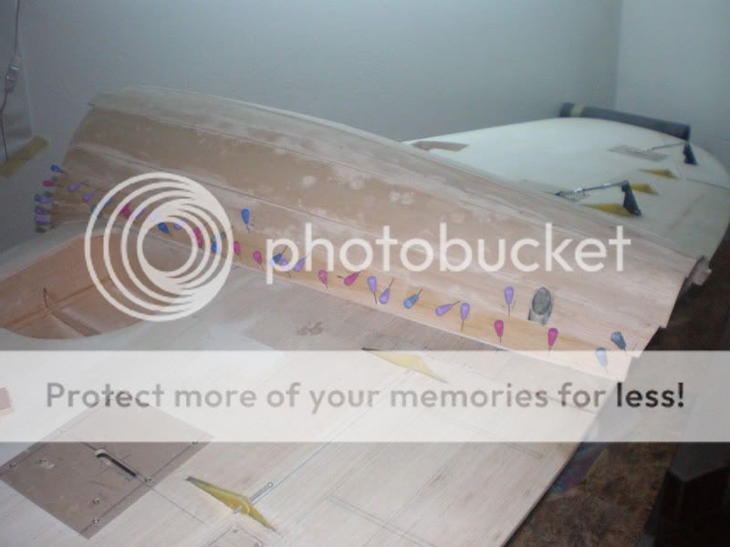
Before go to bed (here is now 2:30 AM) just few more photos. I made all under belly, everything is glued, and middle, dry part, is sand. Tomorrow will be sand all, add filer and sand again...
Screw guide trough under belly was made from paper tube.


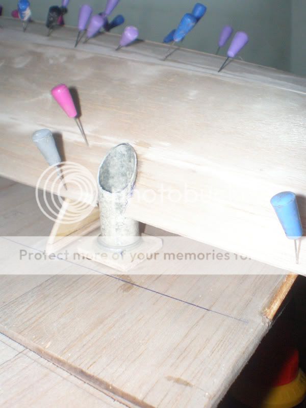
Than I add last balsa plates, and sand middle...


Continue tomorrow...
Good night
Mirce
Before go to bed (here is now 2:30 AM) just few more photos. I made all under belly, everything is glued, and middle, dry part, is sand. Tomorrow will be sand all, add filer and sand again...
Screw guide trough under belly was made from paper tube.
Than I add last balsa plates, and sand middle...
Continue tomorrow...
Good night
Mirce
01-05-2012, 07:19 PM
#178
Join Date: Sep 2007
Location: sydney, AUSTRALIA
Posts: 306
Likes: 0
Received 0 Likes
on
0 Posts
Hi Mirce great build, i managed to get all my retract hardware ,air tank,valve and servo into the belly tank area with a hatch for excess, that way i did not have to join up the air leads when putting the aircraft together and it helped with cutting out the possibly connections leaking as well.
Just an idea.
Dave.
Just an idea.
Dave.
01-06-2012, 02:24 AM
#179
Thread Starter
Helo Dave, thanks for praise for building...
Yes air tank and hardware can be put in underbelly, there is a lot of space for that. I have system like that on my Zero (but, hardware was on inner wing side), and it was great, because in tank always remain some air, and with hand, on air field can open or close retract for easy transportation.
Here is a link to site where is photo of Zero wing: http://www.nsmodelers.rs/warbirds/ze...o-upgrade-kraj
But, P 47 have retract tail wheel, so there must be one air connector, for wing retract - if tanks and hardware is in fuselage, or for tail wheel if put all that stuff in under belly...
I choose first option, but second is good too...
Regards
Mirce
01-06-2012, 06:02 PM
#180
Thread Starter
First thing what I was doing yesterday was to take out from garage my model trailer.

Meister P 47 is very huge and now I need space for working.

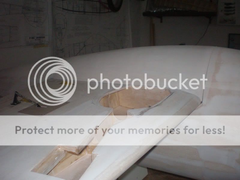
After first sanding I put wing on the fuselage, and sand transitions. After that sanding I add filler and after filler was dry, sand under belly and fuselage again. Results was very good...


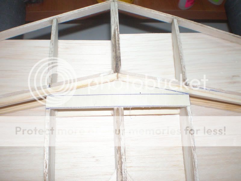
While I waited for the filler get dry I continue work on horizontal stabilizer. I change construction a bit, adding a spars which connect with balsa.


I've made in the middle two ply triangle on which will be later come rib from the fuselage. More about that later...
Marry Christmas
Mirce
Meister P 47 is very huge and now I need space for working.
After first sanding I put wing on the fuselage, and sand transitions. After that sanding I add filler and after filler was dry, sand under belly and fuselage again. Results was very good...
While I waited for the filler get dry I continue work on horizontal stabilizer. I change construction a bit, adding a spars which connect with balsa.
I've made in the middle two ply triangle on which will be later come rib from the fuselage. More about that later...
Marry Christmas
Mirce
 01-07-2012, 04:36 AM
#182
Thread Starter
OK guys, need advice, is this cross in the same line with middle of place where engine shaft go out from the cowl?


Other question is, how deep fuselage go into a cowl?


Cowl on my picture is slipped as much as possible. Is that OK?
And finally, rib one - fire wall is stuck on fuselage just with basla strips ans plates. Is that enough?
On models I made before, engine box passing trough first two - three ribs. That give more rigid construction. Here, on Meister P 47, I can made engine box come trough first and second rib. That will be much stronger, but does I need to do that?
Regards
Mirce
Other question is, how deep fuselage go into a cowl?
Cowl on my picture is slipped as much as possible. Is that OK?
And finally, rib one - fire wall is stuck on fuselage just with basla strips ans plates. Is that enough?
On models I made before, engine box passing trough first two - three ribs. That give more rigid construction. Here, on Meister P 47, I can made engine box come trough first and second rib. That will be much stronger, but does I need to do that?
Regards
Mirce
01-07-2012, 05:32 AM
#183
Mirce
If I remember correctly X marks the spot.
The bottom on the cowl should be flush with the bottom of the fuse. The top beacause of the cowl flaps will overlap the fuse.
I built the glass fuse version but on the wood version I would lay either some Fiberglass or better yet Carbon fiber cloth in and around the fuse where it meets the firewall.
01-07-2012, 05:41 AM
#185

My Feedback: (43)
Yo Mirce:
Engine box: On wood built fuses, I also always run the engine box back to the third rib (former). You're going to need weight up front anyway, might as well make it useful. There's going to be a large engine up front which means lots of vibration: best to distribute the weight to as many formers as possible (also, the box makes a good location to insert the gas tank.)
Cowl location: I always like to just overlap the fuse with just a 1/4" of the cowl. This moves the cowl out as far as possible, moving the engine out farther, which is good for the CG. I also like to make the fuse an inch longer on the nose, helps with the CG and no one notices it and my planes aren't good enough for contests, anyway.
ps: you do extremely good work.
01-07-2012, 05:42 AM
#186
Thread Starter
Wayne, I want to use Evolution 80 with propeller Mejzlik 26x10...
Samprafit, I think that will made engine wood box and put it trough first and second rib... All what did you say you're right... I enjoy watching all your builds too, and pictures from modelers travel...
Thanks
Mirce
Samprafit, I think that will made engine wood box and put it trough first and second rib... All what did you say you're right... I enjoy watching all your builds too, and pictures from modelers travel...
Thanks
Mirce
01-07-2012, 07:10 AM
#189
Thread Starter
OK, here are photos when I put cowl on fuselage and aligned bottom side...
For getting better shape first I put ply rib inside of cowl.

Than I measured 10 mm from the front fuselage edge and add pins. That will be cowl lap on fuselage. Finally I leaned cowl on fuselage. Bottom side was quite closely, but on the upper side was big gap.


So, my question is, was that gap on real P 47 when fins are closed?
What do you think about aligment cowl on fuselage? Is it good?


Or is this better?


I give my vote for first picture, with gap in upper fuselage side. Guys, what do you think?
Regards
Mirce
For getting better shape first I put ply rib inside of cowl.
Than I measured 10 mm from the front fuselage edge and add pins. That will be cowl lap on fuselage. Finally I leaned cowl on fuselage. Bottom side was quite closely, but on the upper side was big gap.
So, my question is, was that gap on real P 47 when fins are closed?
What do you think about aligment cowl on fuselage? Is it good?
Or is this better?
I give my vote for first picture, with gap in upper fuselage side. Guys, what do you think?
Regards
Mirce
01-07-2012, 07:35 AM
#190
My Feedback: (73)
Mirce,
Pushing the cowl as far as it can go is totally wrong. The cowl's lower trailing edge should align up with the fuse. There should be a gap between the fuse and the cowl on the top. You can see from Waynes original build bics, the hardwood cowl stand off mounts to keep the spacing correct for the cowl plate.
Pushing the cowl as far as it can go is totally wrong. The cowl's lower trailing edge should align up with the fuse. There should be a gap between the fuse and the cowl on the top. You can see from Waynes original build bics, the hardwood cowl stand off mounts to keep the spacing correct for the cowl plate.
01-07-2012, 09:50 AM
#194
Thread Starter
Thanks for information, for me that is better option also...
Now, please, when made wooden fuselage, do you made some change in construction between first and second rib, or just leave first rib as it is on the plan?
I saw Wayne made box for engine, but do you change something in connection between rib one and fuselage (I can't see that on picture)? If made what are you done?
I think to made ply wood box for engine which will go trough first and second rib... Some advice...
Regards
Mirce
01-07-2012, 10:01 AM
#195
Mirce
On the wood fuse, it was built to the plans with nothing extra except some reinforcement at the firewall.
Whenever I build something now I always make the firewall stronger.
My suggestion is to use carbon fiber cloth on the inside. Laminate it to the fuse skin and firewall. I like to use at least 5oz cloth.
Your suggestion on the second former is also a good idea, but I would still use the carbon fiber.
You can never make the firewall to strong.
01-07-2012, 10:13 AM
#196
Thread Starter
I'm afraid to big weight of engine & cowl + vibration made to fire wall pull out from the fuselage (after some time, or maybe on some bad landings...).
Carbon reinforcement is good, but it is still on 3mm balsa skin and balsa strips...
Maybe I exaggerating...
Mirce
Carbon reinforcement is good, but it is still on 3mm balsa skin and balsa strips...
Maybe I exaggerating...
Mirce