


ZIROLI 120" B-25 MITCHELL
 04-22-2015, 05:59 PM
#451

On cloudy days, it can kind of be stealth but that can happen with any of my warbirds. The twin beechcraft is sky blue and I've had spotters say: I don't see your plane. Nice bright days are best for all my warbirds. One gets used to it's stealth, as long as you have the transmitter, no problem. If someone just gave me the transmitter and say fly it, there could be trouble! I never take my eye off my planes (my nieuport is the only exception due to it's speed). I've also wiggled the wings to get a perspective of it's flight. I think going through 35 gallons of fuel each season for several seasons and only flying warbirds, you get used to it.
 04-23-2015, 08:59 AM
#452
Outer wings (cont)
Nav and landing lights installed.


The landing lights have their own access panel.
The common wire (ground) for the nav and landing lights were soldered together.

Final ground, nav, landing light wires inserted into the ashlok connector.

4/40 locking nuts added to the flap hinges.

Except for the landing light lens covers and decals, the outer wings are done.

Nav and landing lights installed.
The landing lights have their own access panel.
The common wire (ground) for the nav and landing lights were soldered together.
Final ground, nav, landing light wires inserted into the ashlok connector.
4/40 locking nuts added to the flap hinges.
Except for the landing light lens covers and decals, the outer wings are done.
Last edited by samparfitt; 04-23-2015 at 09:05 AM.
04-27-2015, 06:40 AM
#453
Engines (cont)
Extensions wires.
Throttles:
Each throttle will have it's own channel so two extensions were made. The JR 11X has software set up to handle two engine planes so setup will be easy. The throttle channel and AUX 3 are being used.
Chokes:
I'm partial to servo operated chokes. Aux 2 channel will be used and a Y extension was made for the chokes.
A thin piano wire made it easy to bend the wire into the nacelle and get to the center of the wing.
By accident, I used two wire routing tubes going to the nacelles. Two makes routing wires easier as less likely to snag other wires when pulling wires through with a piano wire. The other tube is for gear and door air lines.


Throttle and choke extensions routed through the tubes and to the nacelles. The female connectors were added after routing to reduce getting snags while pulling the wires through the wing.


Removed engines and servos so the removable fire walls could be painted to fuel proof them.

Extensions wires.
Throttles:
Each throttle will have it's own channel so two extensions were made. The JR 11X has software set up to handle two engine planes so setup will be easy. The throttle channel and AUX 3 are being used.
Chokes:
I'm partial to servo operated chokes. Aux 2 channel will be used and a Y extension was made for the chokes.
A thin piano wire made it easy to bend the wire into the nacelle and get to the center of the wing.
By accident, I used two wire routing tubes going to the nacelles. Two makes routing wires easier as less likely to snag other wires when pulling wires through with a piano wire. The other tube is for gear and door air lines.
Throttle and choke extensions routed through the tubes and to the nacelles. The female connectors were added after routing to reduce getting snags while pulling the wires through the wing.
Removed engines and servos so the removable fire walls could be painted to fuel proof them.
Last edited by samparfitt; 04-27-2015 at 06:46 AM.
04-27-2015, 10:17 AM
#454
Engines (cont)
Re-mounted the engine (DA-50's) and put the servos on the backside of the fire wall. Use Sullivan quik connect ball links on the engine side.
Removable fire walls makes it easy to install and adjust the throttle/choke servo throws.


Plenty of room for the 32 oz dubro tank.

Mounted the fire walls, cowls and TBM 20" 3-blade CF adjustable props.


Re-mounted the engine (DA-50's) and put the servos on the backside of the fire wall. Use Sullivan quik connect ball links on the engine side.
Removable fire walls makes it easy to install and adjust the throttle/choke servo throws.
Plenty of room for the 32 oz dubro tank.
Mounted the fire walls, cowls and TBM 20" 3-blade CF adjustable props.
Last edited by samparfitt; 04-27-2015 at 10:22 AM.
04-27-2015, 10:27 AM
#455
Member
Join Date: Apr 2012
Location: , TN
Posts: 44
Likes: 0
Received 0 Likes
on
0 Posts
A question. If you "Y" the choke servo's together, wouldn't you kill the first engine running while you choke the second to start?
BTW, nice plane,,,,I want one bad!
see you soon,
John
BTW, nice plane,,,,I want one bad!
see you soon,
John
 04-27-2015, 04:43 PM
#457
Nav lights (cont)
There were 4 wires that were, previously, cut so the on/off switch is in the fuse and the remaining nav wires are in the wing.
Two connectors were used for the 4 wires to allow the wing to be removable.
One clear nav light was installed in the right, outside of the vertical fin with an access panel on the opposite side (a 1/64" thick ply panel will be used).
The ground and hot wires for the nav lights were also routed along the center wing to the ashlok connects.
All tested good (still have to install the clear nav light on the left vertical fin: I know I've got the light somewhere, I now have to discover where I left it from last Fall!).

 04-27-2015, 06:04 PM
#459
Dan,
I'm using JR's power safe receiver. It takes in two battery packs, monitors them and takes from the strongest until both are equal, if one goes bad, the other battery is not affected. It has a soft switch, if it goes bad, the receiver defaults to staying on. It handles 30 amps. With these receivers, there is no need for power 'expanders'. And, at around 250 bucks each, they better be good!
I go to 25 flyins a year and have never had a glitch with them yet. The only exception is Joe Nall: nothing is bullet proof against 1200 pilots all turning on their receivers at once (also, why I stop going there).
04-28-2015, 09:21 AM
#461
Landing lights (cont)
The landing lights were tied into the nav light on/off switch with the additional contact switch that will be operated by the gear servo arm (which still needs to be mounted).
With the exception of routing the battery wires to the receiver, the "rat's nest" is done! Almost forgot, air lines to the gear and bomb bay doors still need to be done.
04-29-2015, 01:46 PM
#462
Engine area (cont)
Ignition module:
After connecting the ignition wire to the spark plug, the best location was on top of the engine standoffs. Cut some 1/8" ply and used velcro straps to hold everything together. Some 1/4" thick foam under the ignition module to reduce vibration.


Interesting, the carbs are 180 degrees to each other on the engines. One engine, I bought from a fellow pilot, brand new, 13 years ago: DA had a recall on them and I sent it in and they updated it, free of charge (nice service). The other engine, I bought as a reconditioned engine from DA so, since DA did all the work, I have no idea why each carb is different.
I'm glad the carbs are 180 degrees out as the fuel adjustment screws are facing outward so they will be easy to access. Lucked out in that I put the proper engine on the correct nacelle.


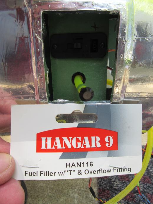
A 3" X 1 7/8" piece of ply was cut for the engine service panels. One heavy duty on/off/charging switch and the fuel filler below it.
Some #4X1" long button head screws were used to secure the service panel to the nacelle.
The switch for the right engine was put in upside down so both ignition switches have the button going to the rear for the ON position.
Using Hanger 9's 3 fuel system, fill and overflow kit.
Spray painted the piano hinge silver and covered the engine doors with aluminum tape and secured the doors to the nacelle using #0 plated screws. With the aluminum tape wrapped around the edges, the doors are pretty snug so I may not have to use any magnets to keep them closed.

A hole was drilled into the nacelle on the inside and outside to route the overflow line to the bottom of the nacelle. Made a separate ply plate so the nut could be secured to the back side of the over flow port. Some small screws used to secure the ply to the side of the nacelle.


Routed the fuel line through some previously cut holes in the fire wall and routed to the carbs.
A 5 cell, 1700 ma batteries are used for juice.
Dubro fuel clips to secure the fuel lines.


Ignition module:
After connecting the ignition wire to the spark plug, the best location was on top of the engine standoffs. Cut some 1/8" ply and used velcro straps to hold everything together. Some 1/4" thick foam under the ignition module to reduce vibration.
Interesting, the carbs are 180 degrees to each other on the engines. One engine, I bought from a fellow pilot, brand new, 13 years ago: DA had a recall on them and I sent it in and they updated it, free of charge (nice service). The other engine, I bought as a reconditioned engine from DA so, since DA did all the work, I have no idea why each carb is different.
I'm glad the carbs are 180 degrees out as the fuel adjustment screws are facing outward so they will be easy to access. Lucked out in that I put the proper engine on the correct nacelle.
A 3" X 1 7/8" piece of ply was cut for the engine service panels. One heavy duty on/off/charging switch and the fuel filler below it.
Some #4X1" long button head screws were used to secure the service panel to the nacelle.
The switch for the right engine was put in upside down so both ignition switches have the button going to the rear for the ON position.
Using Hanger 9's 3 fuel system, fill and overflow kit.
Spray painted the piano hinge silver and covered the engine doors with aluminum tape and secured the doors to the nacelle using #0 plated screws. With the aluminum tape wrapped around the edges, the doors are pretty snug so I may not have to use any magnets to keep them closed.
A hole was drilled into the nacelle on the inside and outside to route the overflow line to the bottom of the nacelle. Made a separate ply plate so the nut could be secured to the back side of the over flow port. Some small screws used to secure the ply to the side of the nacelle.
Routed the fuel line through some previously cut holes in the fire wall and routed to the carbs.
A 5 cell, 1700 ma batteries are used for juice.
Dubro fuel clips to secure the fuel lines.
Last edited by samparfitt; 04-29-2015 at 01:58 PM.
 04-30-2015, 06:03 AM
#464
Engine area (cont)
Fuel tanks.
Dubro 32 oz tanks comes with large 5/32" tubing.
Used K&S tubing benders to keep kinks out of the brass tubing.

Dubro fuel barbs used to secure tubing.
Some oil on the black rubber holes to facilitate inserting brass tubing into those small holes (same for inserting stopper into tank hole).
I find it easier to tighten the stopper using a #4 X 3/4" hex head screw instead of the stock phillips head screw.

Viton fuel line used for clunk lines. The viton stays flexible. A brass tubing used along the clunk line to keep it from doing a '180'.

Carb and vent lines marked so I don't reverse them.
Magic marker tick marks on the top of the brass tubing to insure they are correctly aligned after insertion into the tank.

Fuel tanks.
Dubro 32 oz tanks comes with large 5/32" tubing.
Used K&S tubing benders to keep kinks out of the brass tubing.
Dubro fuel barbs used to secure tubing.
Some oil on the black rubber holes to facilitate inserting brass tubing into those small holes (same for inserting stopper into tank hole).
I find it easier to tighten the stopper using a #4 X 3/4" hex head screw instead of the stock phillips head screw.
Viton fuel line used for clunk lines. The viton stays flexible. A brass tubing used along the clunk line to keep it from doing a '180'.
Carb and vent lines marked so I don't reverse them.
Magic marker tick marks on the top of the brass tubing to insure they are correctly aligned after insertion into the tank.
Last edited by samparfitt; 04-30-2015 at 06:08 AM.
04-30-2015, 08:49 AM
#465
Engine area (cont)
Routed the overflow line around the back of the tank, used a full sheet of 1/4" foam and stuffed the battery on top of the tank.

Maybe they're getting too big....
...when you need a ramp to get them into the trailer!
This baby takes up a lot of room!
The nose has to go in first as the tail is too high to fit under the 2nd shelve.


Routed the overflow line around the back of the tank, used a full sheet of 1/4" foam and stuffed the battery on top of the tank.
Maybe they're getting too big....
...when you need a ramp to get them into the trailer!
This baby takes up a lot of room!
The nose has to go in first as the tail is too high to fit under the 2nd shelve.
Last edited by samparfitt; 04-30-2015 at 08:51 AM.
05-01-2015, 05:41 AM
#466
Nose area:
Forgot about the nose gear steering so a Y extension was needed to connect between the turret servo and nose servo. Still have to decide and where to install the nose gear servo.


Had to use a 2' long drill bit to drill holes through the first two formers to route wires to the batteries and nose gear.


Forgot about the nose gear steering so a Y extension was needed to connect between the turret servo and nose servo. Still have to decide and where to install the nose gear servo.
Had to use a 2' long drill bit to drill holes through the first two formers to route wires to the batteries and nose gear.
05-01-2015, 03:51 PM
#467
Cockpit nose:
Thought it best to get the floor and bulkhead installed before doing the nose gear servo to see what kind of room is available.
I'm using Dbalsa's full cockpit kit.
The main plastic parts were painted green or black. I usually use rustoleum's moss green but I had some leafy green, as that's what I had available.


A paper template was made for the nose cockpit floor before cutting the plastic part.


Ditto for the bulk head.


Left the waste lip on the floor to give it support along the front.
Lots of space under the nose floor to add lead weight.

Thought it best to get the floor and bulkhead installed before doing the nose gear servo to see what kind of room is available.
I'm using Dbalsa's full cockpit kit.
The main plastic parts were painted green or black. I usually use rustoleum's moss green but I had some leafy green, as that's what I had available.
A paper template was made for the nose cockpit floor before cutting the plastic part.
Ditto for the bulk head.
Left the waste lip on the floor to give it support along the front.
Lots of space under the nose floor to add lead weight.
Last edited by samparfitt; 05-01-2015 at 04:09 PM.
05-01-2015, 04:01 PM
#468
Nose canopies:
Put aluminum tape on the canopies and mounted them using #0 screws.
The top nose canopy went on easily. The front nose canopy was difficult. I'm glad I left some tabs along the bottom and sides of the nose canopy as those were needed to secure the canopy to the fuse. The bottom of the canopy doesn't cover the sides of the fuse and just butts up against the edge. I'll have to put a little aluminum tape along those edges.
All canopies are always screwed on as something in the cockpit always comes loose and has to be fixed, plus access to the steering arm of the nose gear.


Adding the BVM oil directly into the gear air cylinders makes a difference on air retentions. After 3 days, it's still strong.

Put aluminum tape on the canopies and mounted them using #0 screws.
The top nose canopy went on easily. The front nose canopy was difficult. I'm glad I left some tabs along the bottom and sides of the nose canopy as those were needed to secure the canopy to the fuse. The bottom of the canopy doesn't cover the sides of the fuse and just butts up against the edge. I'll have to put a little aluminum tape along those edges.
All canopies are always screwed on as something in the cockpit always comes loose and has to be fixed, plus access to the steering arm of the nose gear.
Adding the BVM oil directly into the gear air cylinders makes a difference on air retentions. After 3 days, it's still strong.
Last edited by samparfitt; 05-01-2015 at 04:06 PM.
05-02-2015, 04:29 PM
#469
Side port canopies.
Aluminum taped them, added rivets and only used a few #0 screws to hold them to the fuse since I still have to add the 50 cal's.

Pilot cockpit also taped and riveted. I'm glad I left some wast along the bottom as I must have made the cockpit hole a little too low and the extra is needed to secure the canopy to the sides of the fuse.


Functional top turret taped. Since I need a hole in the top of the turret to secure the base plate that's attached to the servo arm, I added another cross member aluminum tape to hid the hole. After any PM, I can just put a small piece of tape over it.


Aluminum taped them, added rivets and only used a few #0 screws to hold them to the fuse since I still have to add the 50 cal's.
Pilot cockpit also taped and riveted. I'm glad I left some wast along the bottom as I must have made the cockpit hole a little too low and the extra is needed to secure the canopy to the sides of the fuse.
Functional top turret taped. Since I need a hole in the top of the turret to secure the base plate that's attached to the servo arm, I added another cross member aluminum tape to hid the hole. After any PM, I can just put a small piece of tape over it.
05-03-2015, 07:06 AM
#470
Side 50 cal gun pods.
The pods are suppose to be trimmed to their curved edges but I left the flat areas attached at both ends for ease of securing the pods to the side of the fuse using #0 screws.
Epoxied the supplied balsa blocks inside the pods.

Only a thin block was epoxied to the one pod that will be over the service panel.

Filled the corners with aluminum tape and then made templates for the flat areas for applying the aluminum tape.


The supplied resin guns were mounted in the holes drilled out in the front of the pods and secured one of them, so far, to the side of the fuse. A little CA secured the gun to the balsa block.


The pods are suppose to be trimmed to their curved edges but I left the flat areas attached at both ends for ease of securing the pods to the side of the fuse using #0 screws.
Epoxied the supplied balsa blocks inside the pods.
Only a thin block was epoxied to the one pod that will be over the service panel.
Filled the corners with aluminum tape and then made templates for the flat areas for applying the aluminum tape.
The supplied resin guns were mounted in the holes drilled out in the front of the pods and secured one of them, so far, to the side of the fuse. A little CA secured the gun to the balsa block.
Last edited by samparfitt; 05-03-2015 at 07:11 AM.
05-03-2015, 03:20 PM
#471
Pilot's cockpit.
Cut templates for dash, floor and bulkhead and cut those parts.
Dry fitted them into the fuse.


The pilots are cast resin Century jet retract bomber pilots. I had to cut below the knees so they would sit flush to the floor.

With canopy.
Also, installed the other 50 cal pod on the right side.
Cycled the gear to insure cockpit doesn't interfere with nose gear. I used the top of the crutch for the floor (about 2.5" below the side of the fuse opening).

Cut templates for dash, floor and bulkhead and cut those parts.
Dry fitted them into the fuse.
The pilots are cast resin Century jet retract bomber pilots. I had to cut below the knees so they would sit flush to the floor.
With canopy.
Also, installed the other 50 cal pod on the right side.
Cycled the gear to insure cockpit doesn't interfere with nose gear. I used the top of the crutch for the floor (about 2.5" below the side of the fuse opening).
Last edited by samparfitt; 05-03-2015 at 03:37 PM.
05-04-2015, 07:59 AM
#472
Nose gear:
With the main and nose cockpit floors installed to see where to best locate the nose gear servo, I decided to put the nose gear servo in the nose cockpit. Some homemade aluminum servo arms were used and alignment came out to where the bottom of the servo rested at floor level. This makes for a nice short linkage and easy to PM by removing the canopy. I've had nose servos under the main cockpit floor and it's a 'bear' to PM. I needed a servo reverser for the servo. The top of the gear and servo was painted green so, once all the other parts are added to the nose cockpit, the servo will blend into the background.


Receiver batteries.
I was going to use 5000 ma but those are 2 over 3 and I need a flat pack to fit next to the nose gear area. Initially, the batteries were going to be put under the nose cockpit floor but I thought it best to leave that area for any lead that maybe needed for the CG. Some foam holds the battery in place. The steering arm had to be removed to insert the nose gear in the fuse as I made the wood mounts a very close tolerance for the gear mount.


With the main and nose cockpit floors installed to see where to best locate the nose gear servo, I decided to put the nose gear servo in the nose cockpit. Some homemade aluminum servo arms were used and alignment came out to where the bottom of the servo rested at floor level. This makes for a nice short linkage and easy to PM by removing the canopy. I've had nose servos under the main cockpit floor and it's a 'bear' to PM. I needed a servo reverser for the servo. The top of the gear and servo was painted green so, once all the other parts are added to the nose cockpit, the servo will blend into the background.
Receiver batteries.
I was going to use 5000 ma but those are 2 over 3 and I need a flat pack to fit next to the nose gear area. Initially, the batteries were going to be put under the nose cockpit floor but I thought it best to leave that area for any lead that maybe needed for the CG. Some foam holds the battery in place. The steering arm had to be removed to insert the nose gear in the fuse as I made the wood mounts a very close tolerance for the gear mount.
Last edited by samparfitt; 05-04-2015 at 08:03 AM.
05-04-2015, 12:37 PM
#473
cockpits (cont)
Used the belt sander to evenly and quickly remove the plastic in the dash gauge holes.
Some hot glue to secure the gauges to the back of the dash.


Some balsa block hot glued to the plastic parts.

Ball turret installed on nose canopy for the 50 cal.
Secondary hole with cloth for 2nd 50 cal.


Guns, amo belts and ammo boxes painted.


Used the belt sander to evenly and quickly remove the plastic in the dash gauge holes.
Some hot glue to secure the gauges to the back of the dash.
Some balsa block hot glued to the plastic parts.
Ball turret installed on nose canopy for the 50 cal.
Secondary hole with cloth for 2nd 50 cal.
Guns, amo belts and ammo boxes painted.
Last edited by samparfitt; 05-04-2015 at 12:40 PM.
05-04-2015, 03:53 PM
#474
Top turret (cont)
Drilled some holes in the plastic canopy and mounted the guns as well as the ply floor using some #0 screws. The turret was tested and she rotates with the rudders.

Nose cockpit (cont)
Mounted the ammo boxes to the ammo tray and to the right bulkhead. Mounted the two guns in the front canopy and routed the bullets and guide from ammo boxes to the gun.


Drilled some holes in the plastic canopy and mounted the guns as well as the ply floor using some #0 screws. The turret was tested and she rotates with the rudders.
Nose cockpit (cont)
Mounted the ammo boxes to the ammo tray and to the right bulkhead. Mounted the two guns in the front canopy and routed the bullets and guide from ammo boxes to the gun.
05-05-2015, 06:11 AM
#475
CG:
Per Henrik, I set my CG at 6" back from the LE at the fuse. At the end of the inner wing that came out to be 4.5" back from the LE.
I used my general purpose CG kit: a large dowel cut in half and taped to the bottom of the wing and a flat piece of wood taped to my general plane stand.


Doors aren't on but they are balsa plus they are all around the CG. Put the gear up and poured lead buckshot in a butter bowl until she was just slightly nose heavy. Using my 'people' scale, an extra 4 pounds (exactly) is needed for nose weight. Not bad for a 45 lb plane. Those cast resin pilots and cockpit parts up front also help along with making the nacelles longer on the engine side.
Some epoxy was mixed into the buckshot and poured into the nose area. I, first, slopped on epoxy on the inside of the nose to insure good contact with the wood. I normally make a weight box that goes over the engine but, obviously, this was the better solution in this case. Initially, I was going to make a weight box for the nose but, with the compound curves, it wasn't practical.


Figure it was best to get the CG done before I start putting all that nose detail into the front.
Per Henrik, I set my CG at 6" back from the LE at the fuse. At the end of the inner wing that came out to be 4.5" back from the LE.
I used my general purpose CG kit: a large dowel cut in half and taped to the bottom of the wing and a flat piece of wood taped to my general plane stand.
Doors aren't on but they are balsa plus they are all around the CG. Put the gear up and poured lead buckshot in a butter bowl until she was just slightly nose heavy. Using my 'people' scale, an extra 4 pounds (exactly) is needed for nose weight. Not bad for a 45 lb plane. Those cast resin pilots and cockpit parts up front also help along with making the nacelles longer on the engine side.
Some epoxy was mixed into the buckshot and poured into the nose area. I, first, slopped on epoxy on the inside of the nose to insure good contact with the wood. I normally make a weight box that goes over the engine but, obviously, this was the better solution in this case. Initially, I was going to make a weight box for the nose but, with the compound curves, it wasn't practical.
Figure it was best to get the CG done before I start putting all that nose detail into the front.
Last edited by samparfitt; 05-05-2015 at 06:18 AM.