


ZIROLI 120" B-25 MITCHELL
 05-05-2015, 07:53 AM
#476

Join Date: Dec 2003
Location: manchester, AE, UNITED KINGDOM
Posts: 1,795
Likes: 0
Received 0 Likes
on
0 Posts
Ours was set at 6" gear up, it was not comfy to fly, but safe, a lot of ballast was removed, Can i suggest you make access, to removevsome ballast, if she flies nose heavy, Looking more than superb, beutifull
 05-05-2015, 07:53 AM
#477
Join Date: Dec 2003
Location: manchester, AE, UNITED KINGDOM
Posts: 1,795
Likes: 0
Received 0 Likes
on
0 Posts
Ours was set at 6" gear up, it was not comfy to fly, but safe, a lot of ballast was removed, Can i suggest you make access, to removevsome ballast, if she flies nose heavy, Looking more than superb, beutifull
05-05-2015, 10:12 AM
#478

Alan,
I only added 4 lbs and it would probably be easier to add a little tail weight versus going through the nose cockpit and removing the cockpit detail.
============
Side gun blisters:
Some brown cloth from the kit was secured under some thin aluminum and #0 plated screws.
Just the gun barrel was used and epoxied to the 3/8" hole in the clear plastic blister.


A thin lip was left around the blister to easily mount the side blisters to the fuse using #0 screws.


I only added 4 lbs and it would probably be easier to add a little tail weight versus going through the nose cockpit and removing the cockpit detail.
============
Side gun blisters:
Some brown cloth from the kit was secured under some thin aluminum and #0 plated screws.
Just the gun barrel was used and epoxied to the 3/8" hole in the clear plastic blister.
A thin lip was left around the blister to easily mount the side blisters to the fuse using #0 screws.
Last edited by samparfitt; 05-05-2015 at 10:18 AM.
05-05-2015, 12:47 PM
#479
Nose cockpit (cont)
A sheet of balsa was epoxied only down the center to the bottom of the floor as the floor needs to bend a little to get by the ammo tray.

Everything is screwed in.
The large console on the left is the nordic bomb site control panel. The large black pipe is the heating system. The silver pipe is the conduit. Some homemade straps out of very thin aluminum were made to hold the heating system and conduit. Toggles are hex nuts and aluminum wire.
There is a comm. panel just back of the nordic panel. A black service panel for the conduit is on the back bulkhead.
The bombardier has velcro on his back side to hold him in his seat plus a velcro strap goes over his lap and down through the floor. Also, had to cut his legs off below the knees to fit in the available space.
The lower right gun has velcro on it to secure it to the velcro on the floor to keep it from moving. A slot was cut in the top gun where the ammo belt is fed through it during assembly. A slot was also cut in the end of the ammo box, the ammo tray was secured to the box with a screw.


A sheet of balsa was epoxied only down the center to the bottom of the floor as the floor needs to bend a little to get by the ammo tray.
Everything is screwed in.
The large console on the left is the nordic bomb site control panel. The large black pipe is the heating system. The silver pipe is the conduit. Some homemade straps out of very thin aluminum were made to hold the heating system and conduit. Toggles are hex nuts and aluminum wire.
There is a comm. panel just back of the nordic panel. A black service panel for the conduit is on the back bulkhead.
The bombardier has velcro on his back side to hold him in his seat plus a velcro strap goes over his lap and down through the floor. Also, had to cut his legs off below the knees to fit in the available space.
The lower right gun has velcro on it to secure it to the velcro on the floor to keep it from moving. A slot was cut in the top gun where the ammo belt is fed through it during assembly. A slot was also cut in the end of the ammo box, the ammo tray was secured to the box with a screw.
Last edited by samparfitt; 05-05-2015 at 12:58 PM.
05-06-2015, 08:29 AM
#481
Pilot's cockpit (cont)
Some balsa sheet was glued to the crutch as well as some 1/8" ply along the front where I wanted some extra strength for the cast resin steering assemblies.

All parts were screwed in for PM. The small panels on the left and right side were hot glued to the walls since they won't interfere with removing the major cockpit parts.
The back bulkhead was first, then the floor and then the dash.
Some shaped balsa block was CA'ed to the curved parts of the center console to hold the throttles, etc in place.
The steering assemblies are all cast resin, except for the column. Some servo screws were used to secure the steering columns to the floor from the nose gear area. Ditto for the yellow cast resin oxygen tanks located behind the pilot's seat. Some holes were drilled in the tops and black rubber tubing was CA'ed in the holes.
The seats were screwed to the floor and then velcro was taped to the bottom of the pilots and the seat.
The canopy is screwed on using #0 screws. One nice offset of using aluminum tape is the edge of the canopy is not noticeable versus on my P-61 painted lite green, the screwed on canopy doesn't look nearly as nice.


Some balsa sheet was glued to the crutch as well as some 1/8" ply along the front where I wanted some extra strength for the cast resin steering assemblies.
All parts were screwed in for PM. The small panels on the left and right side were hot glued to the walls since they won't interfere with removing the major cockpit parts.
The back bulkhead was first, then the floor and then the dash.
Some shaped balsa block was CA'ed to the curved parts of the center console to hold the throttles, etc in place.
The steering assemblies are all cast resin, except for the column. Some servo screws were used to secure the steering columns to the floor from the nose gear area. Ditto for the yellow cast resin oxygen tanks located behind the pilot's seat. Some holes were drilled in the tops and black rubber tubing was CA'ed in the holes.
The seats were screwed to the floor and then velcro was taped to the bottom of the pilots and the seat.
The canopy is screwed on using #0 screws. One nice offset of using aluminum tape is the edge of the canopy is not noticeable versus on my P-61 painted lite green, the screwed on canopy doesn't look nearly as nice.
Last edited by samparfitt; 05-06-2015 at 08:37 AM.
05-06-2015, 02:32 PM
#482
Horizontal stab to fuse fillet.
After taping, used easysand to fill in the fillets.
After sanding, the aluminum tape and rivets were added.


Looks done but lots of stuff to do yet, all the doors and tail gunner. I might make some of the windows open: hard to see all that cockpit detail


After taping, used easysand to fill in the fillets.
After sanding, the aluminum tape and rivets were added.
Looks done but lots of stuff to do yet, all the doors and tail gunner. I might make some of the windows open: hard to see all that cockpit detail
Last edited by samparfitt; 05-06-2015 at 02:38 PM.
 05-07-2015, 10:24 AM
#487
Thanks guys.
I answered your PM. I wish this web site would go back to making private messages in red, like they used to be, so I would notice them. It would take all of 5 minutes to make that change.
A museum piece: that's what women say I am!
See ya' in 5 weeks, Scott. I need to email Frank to get another 100 of those safety clips: I go through them like pop corn: the last batch is all gone.
No work on the B-25, today.
I had to cut the grass and detail up the truck for summer: full wash, wax, vacuum and interior cleanup.
Of course under the hood (bonnet for you Brits) gets a full cleaning, also
Not bad for an 11 old truck (in car years, that's old!)
My butt's tired: took all day to do two things!
Last edited by samparfitt; 05-07-2015 at 10:29 AM.
05-08-2015, 08:16 AM
#488
Tail gunner:
Aluminum taped the tail gunner's cockpit.

An ABS white semi circle piece in the Ziroli kit is the gun pod (at least that's what I assumed). It really doesn't fit the rectangular shape of the fuse but I forced it to fit! After cutting the edges off to a reasonable close fit, I screwed the pod to the fuse with some #1X1/2" screws while forcing the edge to the fuse.
A dremel sanding drum was then used to smooth the pod's edges to the fuse.


I had a soft rubber pilot bust that I used for the gunner. Glued him to a piece of balsa and glued it onto the fuse stringers.

Holes drilled in the gun pod and the 50 cals were epoxied in place.
With the vertical sides of the canopy preventing using any screws, I just aluminum taped the canopy to the fuse.
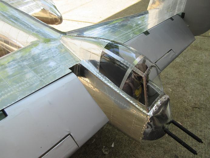


A skid was put on the bottom of the fuse tail as, surely, I'll scrape the bottom on take offs.

I probably should make the nose and tail guns a 'screw on barrel' using some 4/40 rod as surely they are going to get snapped off
Aluminum taped the tail gunner's cockpit.
An ABS white semi circle piece in the Ziroli kit is the gun pod (at least that's what I assumed). It really doesn't fit the rectangular shape of the fuse but I forced it to fit! After cutting the edges off to a reasonable close fit, I screwed the pod to the fuse with some #1X1/2" screws while forcing the edge to the fuse.
A dremel sanding drum was then used to smooth the pod's edges to the fuse.
I had a soft rubber pilot bust that I used for the gunner. Glued him to a piece of balsa and glued it onto the fuse stringers.
Holes drilled in the gun pod and the 50 cals were epoxied in place.
With the vertical sides of the canopy preventing using any screws, I just aluminum taped the canopy to the fuse.
A skid was put on the bottom of the fuse tail as, surely, I'll scrape the bottom on take offs.
I probably should make the nose and tail guns a 'screw on barrel' using some 4/40 rod as surely they are going to get snapped off
Last edited by samparfitt; 05-08-2015 at 08:24 AM.
05-08-2015, 01:26 PM
#489
Bomb bay doors.
As mentioned previously, the doors were built before sheeting and, after sheeting, the doors were cut out.
Dubro heavy duty hinges were epoxied to the doors and fuse frame.
I can never get doors to work with only a 1" throw so I always use UP's 1.5" throws.
Some dubro ball links are used on the door side. I drilled/tapped the ball link for the UP's 4/40 air rod.
I usually need to use control horns but they were not needed.
The rotating base for the UP cylinders were missing so I had to make some out of brass. Some 2/56 bolt/lock nuts hold them together.

Initially, I thought I could put the base of the air cylinder along the vertical outside walls but the geometry wasn't working. Instead, I epoxied some aircraft ply to the horizontal cross crutch and used hex head servo screws to secure the base of the air cylinder to the ply.
The ball link has to be as close as possible to the inside surface of the door to get max air cylinder movement.
I put the linkage in the center of the doors to prevent any racking. This should work well with bombs in the front and back of the linkage. The formers of the doors are aircraft ply so the ball link will not rip out versus possible failure with lite ply.


The original brass cotter pins were removed and one long wire is used as the hinge pin. A Z type bend was made in one end to keep the wire from vibrating out.

Cycle test.
The bomb bay doors and brakes are on their own air tank and fill valve.


As mentioned previously, the doors were built before sheeting and, after sheeting, the doors were cut out.
Dubro heavy duty hinges were epoxied to the doors and fuse frame.
I can never get doors to work with only a 1" throw so I always use UP's 1.5" throws.
Some dubro ball links are used on the door side. I drilled/tapped the ball link for the UP's 4/40 air rod.
I usually need to use control horns but they were not needed.
The rotating base for the UP cylinders were missing so I had to make some out of brass. Some 2/56 bolt/lock nuts hold them together.
Initially, I thought I could put the base of the air cylinder along the vertical outside walls but the geometry wasn't working. Instead, I epoxied some aircraft ply to the horizontal cross crutch and used hex head servo screws to secure the base of the air cylinder to the ply.
The ball link has to be as close as possible to the inside surface of the door to get max air cylinder movement.
I put the linkage in the center of the doors to prevent any racking. This should work well with bombs in the front and back of the linkage. The formers of the doors are aircraft ply so the ball link will not rip out versus possible failure with lite ply.
The original brass cotter pins were removed and one long wire is used as the hinge pin. A Z type bend was made in one end to keep the wire from vibrating out.
Cycle test.
The bomb bay doors and brakes are on their own air tank and fill valve.
Last edited by samparfitt; 05-08-2015 at 01:36 PM.
05-11-2015, 12:52 PM
#493
Left gun pods (which cover the service panel).
Some balsa block was shaped and glued into the back of the top gun pod. After putting the gun pod over the service panel, I drilled an 1/8" hole in the front of the pod and through the fuse and into the inner ply, removed the pod and then drilled a 1/4" hole in the pod and fuse.
Some 1/4" aluminum dowel was used for durability and blend in with the aluminum tape. I drilled a hole on one end of two rods that were about 3" long. A wire clip was made to go through the hole in the aluminum rod and hold the gun pod to the side of the fuse.
The front rod was pushed through the pod and into the fuse and the rod was epoxied from the inside of the fuse.
After the front rod was done, I drilled and epoxied the rod to the back of the gun pod.
Last, the lower gun pod was attached to the fuse using #0 screws.
The wire holding clips aren't too scale but they blend into the aluminum finish so easily, that they are not noticeable unless you get eye level and next to the pods.
Last edited by samparfitt; 05-11-2015 at 12:58 PM.
05-12-2015, 01:52 PM
#495
Thanks, Chris,
==========
Main gear doors:
I'm using two UP 1.5" air cylinders to move the two doors on each main gear. I have a UP 4 secondary air valve for the one small door that stays open when the gear is down.
It took awhile to figure out how to mount the air cylinders as the main strut is very close to one side so there's not a lot of room for an air cylinder.
I have some BVM air cylinders but they rotated 90 degrees to the way that the UP air cylinders rotate and couldn't be used. The air cylinders need to rotate several degrees as the door moves.
I epoxied some 1/8" thick by 1" wide air craft ply across the two gear mounts. A hole was needed in the ply for the top air nipple. There was just enough room for the air cylinder between the main strut and wood gear mount. I had to grind a small slot in the wood mount so the air cylinder could rotate when the door is open. I made the wood mounts larger than the plans so the notch shouldn't compromise the strength of the mount. The picture shows the air cylinder temporarily rotated so I could grind the wood mount.


With the air cylinder mounted so high in the gear well, a coupler extension was needed to lengthen the air cylinder rod. A dubro ball socket and control horn was used on the door side.


One side is done and all works well. The one small door that stays open when the gear is down still needs to be made operational.
As can be seen in the pictures, hinges for the main doors are only on the front end, due to the severe curve of the door opening, this was the only option available. Not prototype but, fortunately, the doors are only open for a few seconds when the gear is going up or down so the odd door hinging is really never seen.
A spare small door was made and screwed in place (needed for easy removal of the gear from the nacelle).


==========
Main gear doors:
I'm using two UP 1.5" air cylinders to move the two doors on each main gear. I have a UP 4 secondary air valve for the one small door that stays open when the gear is down.
It took awhile to figure out how to mount the air cylinders as the main strut is very close to one side so there's not a lot of room for an air cylinder.
I have some BVM air cylinders but they rotated 90 degrees to the way that the UP air cylinders rotate and couldn't be used. The air cylinders need to rotate several degrees as the door moves.
I epoxied some 1/8" thick by 1" wide air craft ply across the two gear mounts. A hole was needed in the ply for the top air nipple. There was just enough room for the air cylinder between the main strut and wood gear mount. I had to grind a small slot in the wood mount so the air cylinder could rotate when the door is open. I made the wood mounts larger than the plans so the notch shouldn't compromise the strength of the mount. The picture shows the air cylinder temporarily rotated so I could grind the wood mount.
With the air cylinder mounted so high in the gear well, a coupler extension was needed to lengthen the air cylinder rod. A dubro ball socket and control horn was used on the door side.
One side is done and all works well. The one small door that stays open when the gear is down still needs to be made operational.
As can be seen in the pictures, hinges for the main doors are only on the front end, due to the severe curve of the door opening, this was the only option available. Not prototype but, fortunately, the doors are only open for a few seconds when the gear is going up or down so the odd door hinging is really never seen.
A spare small door was made and screwed in place (needed for easy removal of the gear from the nacelle).
Last edited by samparfitt; 05-12-2015 at 02:02 PM.
05-13-2015, 03:26 PM
#496
Nose gear doors.
There are two doors: one long that closes after the gear comes down and one short door that is next to the strut and stays open when the gear is down.
I'm out of UP air cylinders so I used the 1" throw robart 165 for the short front door. The strut is a few inches behind the leading edge of the door so I could angle the air cylinder in the opening without interfering with the gear. The nose cockpit floor had to be removed to epoxy a piece of air craft ply over the gear wooden mounts. The base of the air cylinder was screwed to the ply and a dubro ball link and control horn was used on the door side. The control horns first hole was used to get max air cylinder throw by keeping the end point as close as possible to the inside face of the door.
A manual air pump was used to check that the door is working properly. Later, this door will be connected to the UP 4 air valve.

The larger door for the nose gear was done in the same fashion as the small door, except I couldn't angle the air cylinder as the strut has to pass by this area. Another ply was epoxied to the top of the wood mounts. I couldn't get the door to open wide enough so the strut would not hit the door so I tried something new. I bent the 2/56 threaded rod at a 90 degree angle to give clearance of the air cylinder piston along the inside edge of the door. I had my doubts that this would work since I thought the force would turn the 2/56 rod being at a 90 degree angle but it worked....so far!
This door's air lines were connected up to the UP valve and all worked properly.


Some home depot wire harnesses to keep the wires away from the nose gear.

There are two doors: one long that closes after the gear comes down and one short door that is next to the strut and stays open when the gear is down.
I'm out of UP air cylinders so I used the 1" throw robart 165 for the short front door. The strut is a few inches behind the leading edge of the door so I could angle the air cylinder in the opening without interfering with the gear. The nose cockpit floor had to be removed to epoxy a piece of air craft ply over the gear wooden mounts. The base of the air cylinder was screwed to the ply and a dubro ball link and control horn was used on the door side. The control horns first hole was used to get max air cylinder throw by keeping the end point as close as possible to the inside face of the door.
A manual air pump was used to check that the door is working properly. Later, this door will be connected to the UP 4 air valve.
The larger door for the nose gear was done in the same fashion as the small door, except I couldn't angle the air cylinder as the strut has to pass by this area. Another ply was epoxied to the top of the wood mounts. I couldn't get the door to open wide enough so the strut would not hit the door so I tried something new. I bent the 2/56 threaded rod at a 90 degree angle to give clearance of the air cylinder piston along the inside edge of the door. I had my doubts that this would work since I thought the force would turn the 2/56 rod being at a 90 degree angle but it worked....so far!
This door's air lines were connected up to the UP valve and all worked properly.
Some home depot wire harnesses to keep the wires away from the nose gear.
Last edited by samparfitt; 05-13-2015 at 03:31 PM.
05-14-2015, 07:36 AM
#497
Receiver batteries:
Some extensions made for the blue connectors on one end and regular connectors on the other end. With the receiver on the wing and batteries/charger outlets and switch in the fuse, two separate extensions were needed.
Two Y extensions made to connect the receiver to the batteries/charger outlet. Oddball Y extension needed with a male and female connector on the Y side.

Power safe receiver makes for a compact service panel with only needing one small on/off soft switch and two charging jacks.

One more item done:

Some extensions made for the blue connectors on one end and regular connectors on the other end. With the receiver on the wing and batteries/charger outlets and switch in the fuse, two separate extensions were needed.
Two Y extensions made to connect the receiver to the batteries/charger outlet. Oddball Y extension needed with a male and female connector on the Y side.
Power safe receiver makes for a compact service panel with only needing one small on/off soft switch and two charging jacks.
One more item done:
Last edited by samparfitt; 05-14-2015 at 07:38 AM.
 05-14-2015, 11:08 AM
#499
Sounds good to me!
==================
UP 4 valve install.
The UP 4 does the 3 extra small doors that stay open when the gear is down (for strut clearance).
No servo controls this valve but the strut down on the UP 2 air valve controls the UP 2 valve.
So far, I ran lines to the small nose door and all is working fine.


Having 8 doors (some close when gear is down, some open when gear is down) makes for a lot of extra air tubing: 6 air lines to the nose. It is pretty cool and is fun to set up but I doubt if most pilots know about the B-25 gear doors and, since the doors only move when the gear is going up or down, most people will not even see it!
I would understand if most builders of B-25's left the small doors off; it was difficult finding air cylinder room on this monster, let alone a smaller version..
In the picture, the UP 2 is at the top and the UP 4 is at the bottom.
I'll dread ever having to take the wing off the fuse: would probably take an hour just to disconnect all wires and air lines
All work done on the plane is on my low stand with the plane right side up. She's too heavy, mostly too bulky, for one person to flip over plus all the hanger rash that would occur! Working on the gear is like changing the oil on your vehicle: crawl under and do your work.
Counting the double air cylinders for each main gear, there are 13 air cylinders: I would say two large robart air cylinders are minimum requirements (make that 15, forgot the bomb bay doors, separate large air tank also used for brakes).
There are 18 servos (not yet counting bomb drops).
Ail: 2
Flaps: 4
El: 2
Rud: 2
turret: 1
gear: 1
brakes: 1
bomb bay doors: 1
throttle/choke: 4
(good reason to have 8400 ma's!)


==================
UP 4 valve install.
The UP 4 does the 3 extra small doors that stay open when the gear is down (for strut clearance).
No servo controls this valve but the strut down on the UP 2 air valve controls the UP 2 valve.
So far, I ran lines to the small nose door and all is working fine.
Having 8 doors (some close when gear is down, some open when gear is down) makes for a lot of extra air tubing: 6 air lines to the nose. It is pretty cool and is fun to set up but I doubt if most pilots know about the B-25 gear doors and, since the doors only move when the gear is going up or down, most people will not even see it!
I would understand if most builders of B-25's left the small doors off; it was difficult finding air cylinder room on this monster, let alone a smaller version..
In the picture, the UP 2 is at the top and the UP 4 is at the bottom.
I'll dread ever having to take the wing off the fuse: would probably take an hour just to disconnect all wires and air lines
All work done on the plane is on my low stand with the plane right side up. She's too heavy, mostly too bulky, for one person to flip over plus all the hanger rash that would occur! Working on the gear is like changing the oil on your vehicle: crawl under and do your work.
Counting the double air cylinders for each main gear, there are 13 air cylinders: I would say two large robart air cylinders are minimum requirements (make that 15, forgot the bomb bay doors, separate large air tank also used for brakes).
There are 18 servos (not yet counting bomb drops).
Ail: 2
Flaps: 4
El: 2
Rud: 2
turret: 1
gear: 1
brakes: 1
bomb bay doors: 1
throttle/choke: 4
(good reason to have 8400 ma's!)
Last edited by samparfitt; 05-14-2015 at 11:34 AM.

