


Royal Zero Kit Build into Rufe
 01-14-2018, 04:31 PM
#226

With the heavy sanding / shaping work on the cowling finished, a little cosmetic spackling w/ House Bondo and a last outer glassing w/ 3/4 oz. cloth should be the end of this stage. Six millimeters were taken off the aft end of the cowling perimeter and its looking better & better. At some point, the forward edge of the fuse will get rounded and the cowl will overlap it by 1/4" and that should get the side profile right on the money. Before that takes place, the
carburetor scoop needs to be fabricated and attached, then the cowl top gun troughs.
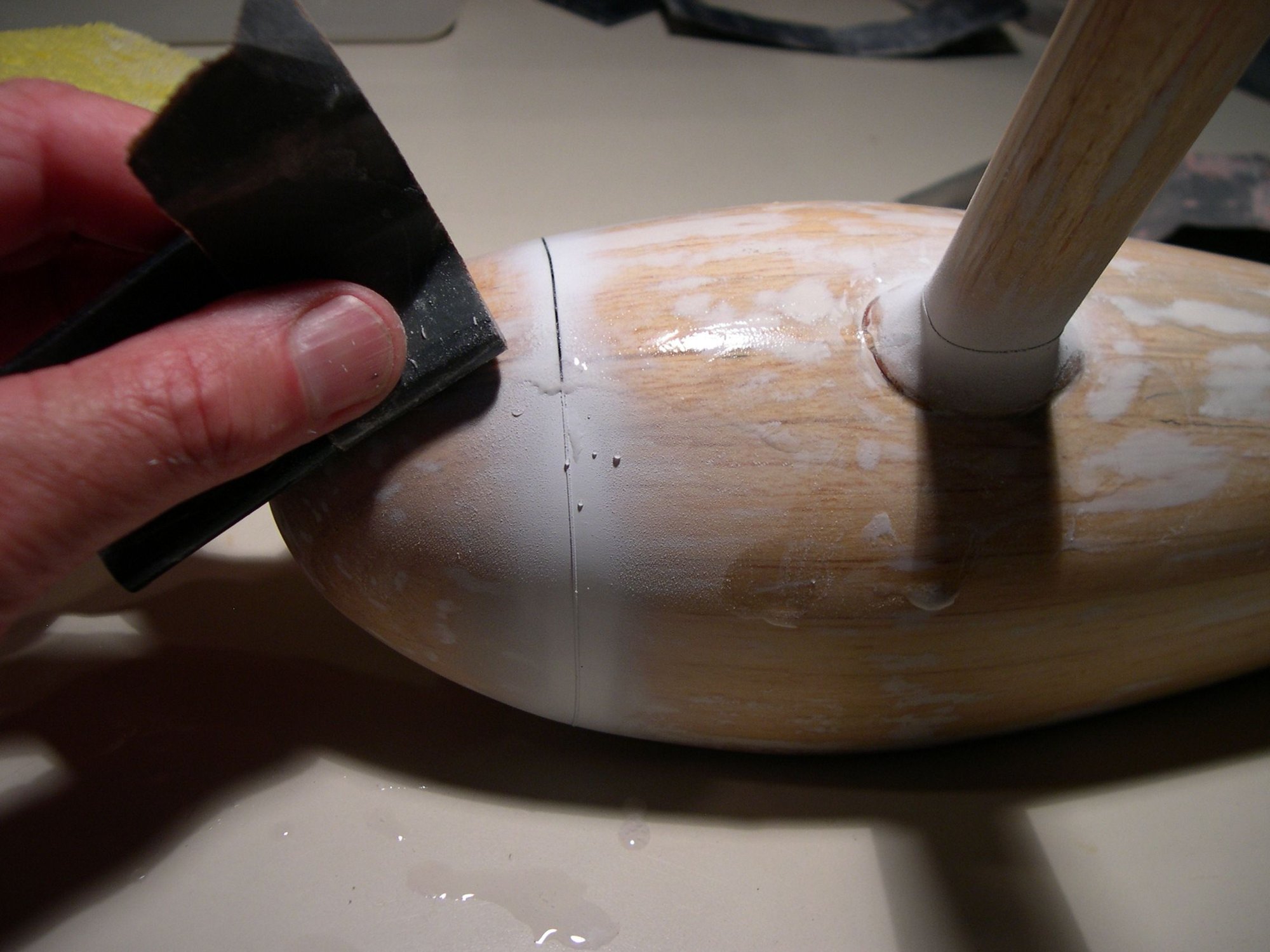
The static display blue foam spinner got 3 layers of panty hose draped and resined over it and will be put aside until the static display prop gets fabricated. G.
carburetor scoop needs to be fabricated and attached, then the cowl top gun troughs.
The static display blue foam spinner got 3 layers of panty hose draped and resined over it and will be put aside until the static display prop gets fabricated. G.

 01-25-2018, 04:56 PM
#228
With the cowling fitted to the fuse, the temporary marker locations of the nose gun ports were revised and forward ends cut off and set back for the bondo rhinoplasti work-up. A sharpened brass tube was used to make the nostrils that would later house the machine guns. Once hollowed out, the brass tube was vaselined just where the bondo was going to be applied over it and once hardened, the tube was easily removed. Cutting and sanding got it to where it resembled the look I was after. In my opinion, the bondo approach worked much better than balsa or basswood in this step, providing good definition and symmetry.
Drawn lines were carried forth onto the cowling to delineate the gun troughs and the cutting was done with a deft touch using a Dremel saw bit. With a brass tube wrapped in sandpaper, the troughs were final sanded to the correct half-round depth and then glassed w/ 3/4 oz. cloth to finish it off. Next step...... lower carb intake fabrication. G.
Drawn lines were carried forth onto the cowling to delineate the gun troughs and the cutting was done with a deft touch using a Dremel saw bit. With a brass tube wrapped in sandpaper, the troughs were final sanded to the correct half-round depth and then glassed w/ 3/4 oz. cloth to finish it off. Next step...... lower carb intake fabrication. G.
Last edited by southpaw50; 01-26-2018 at 06:35 AM.
01-25-2018, 07:41 PM
#230
Thanks. I'm surprised more R/C modelers haven't implemented House Bondo in their builds. It solidifies in 2 - 3 minutes, can be carved while still pliable and sands to a remarkable feather edge over balsa. It can be heavy by nature but when used sparingly ( and strategically ), its some kind of slick!
02-04-2018, 11:48 AM
#231
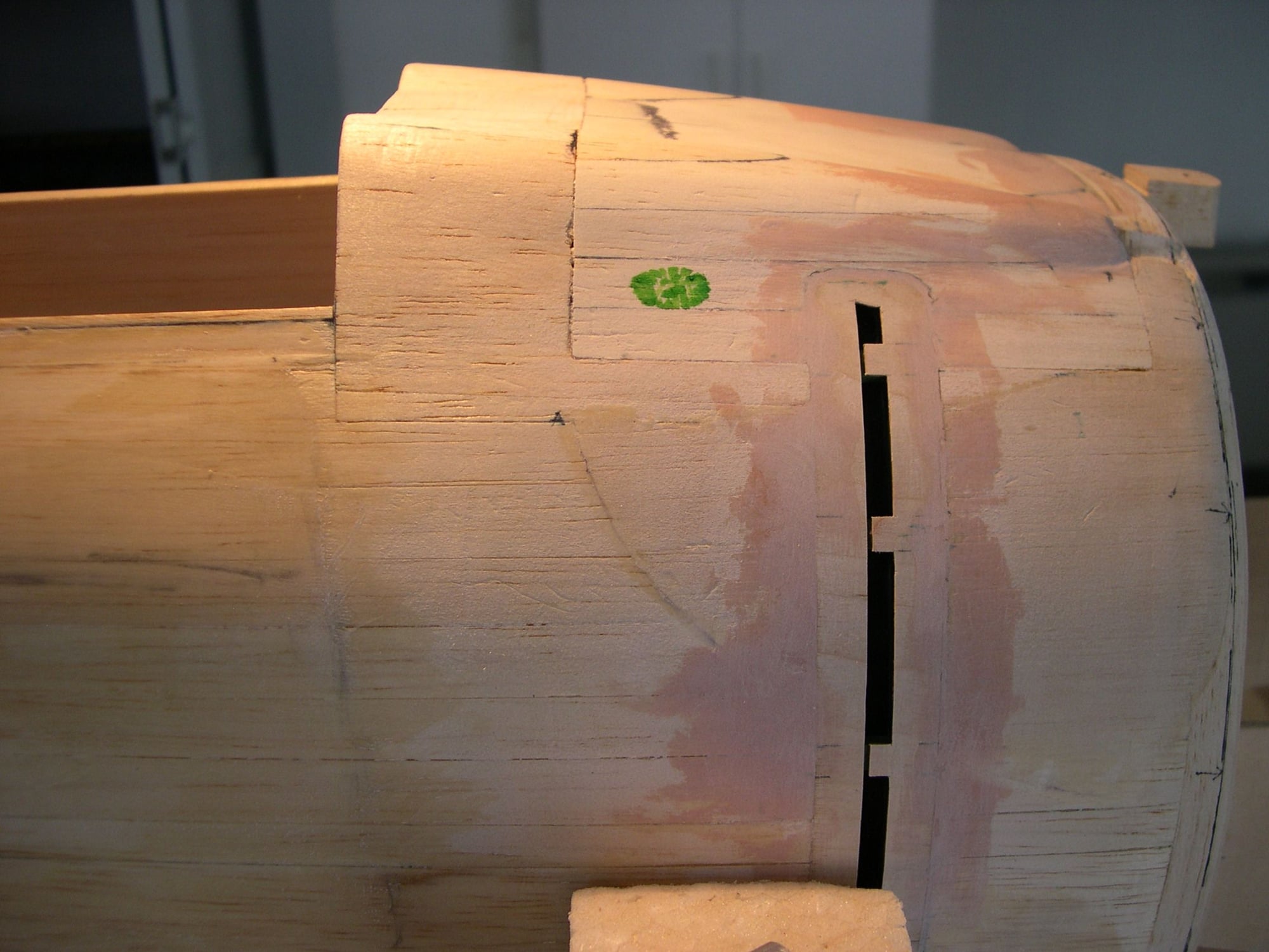
Once I had a blue foam blank shaped to match the cowl bottom, I traced the side view contour to its side and cut it to its initial shape. A 1/8" ply intake "face" was epoxied to the foam blank and a cut-out was sanded into the front of the cowl to "key" the front of the assembly in place. The carb opening outline was formulated and traced & transferred to the ply & fit checked. ( Not visible is a temporary 5" piece of 1/4" ply glued inside of the cowl to the foam in order to hold everything in place in a vise while 5 lams of 1 oz. cloth were added. )
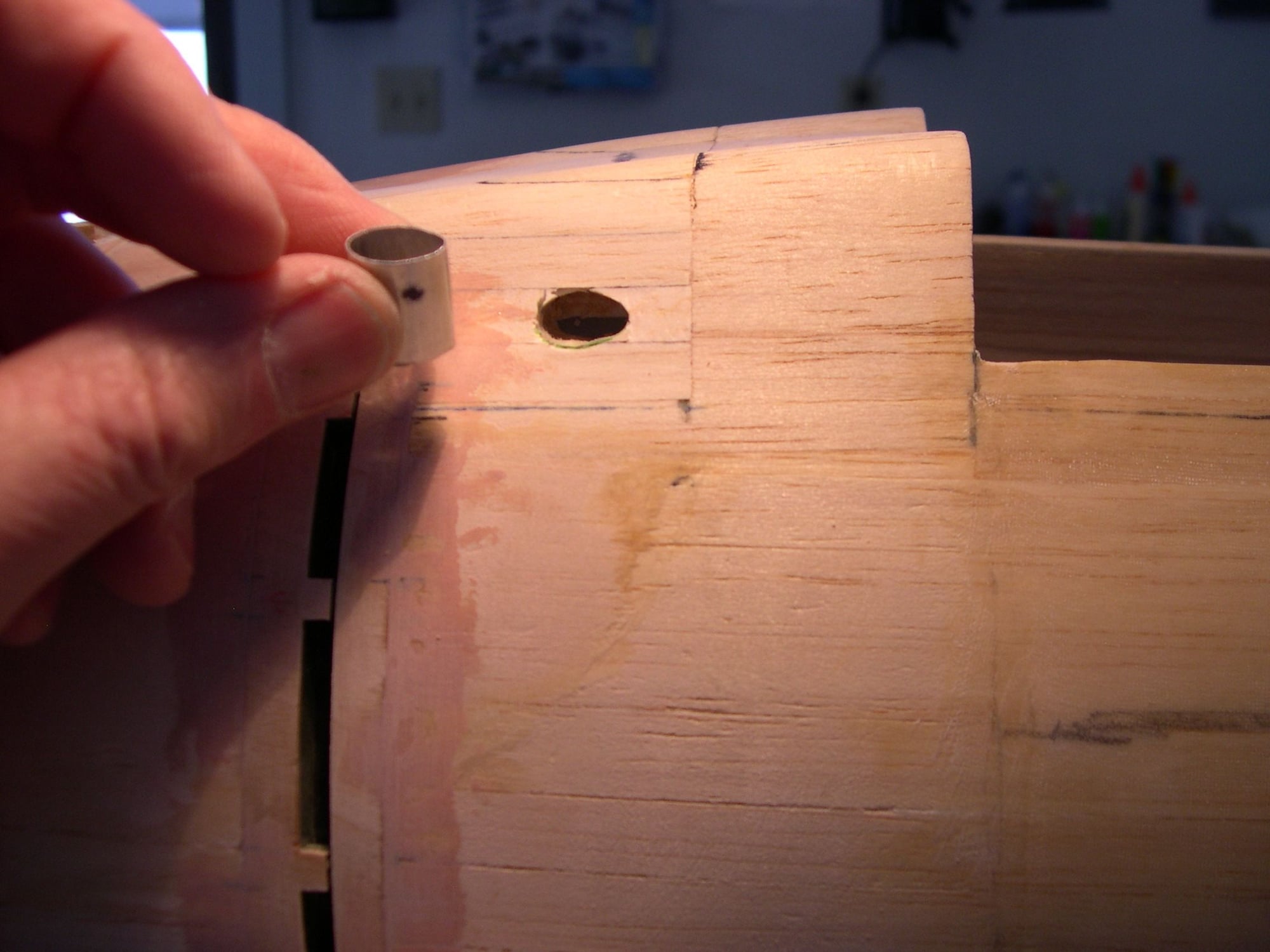
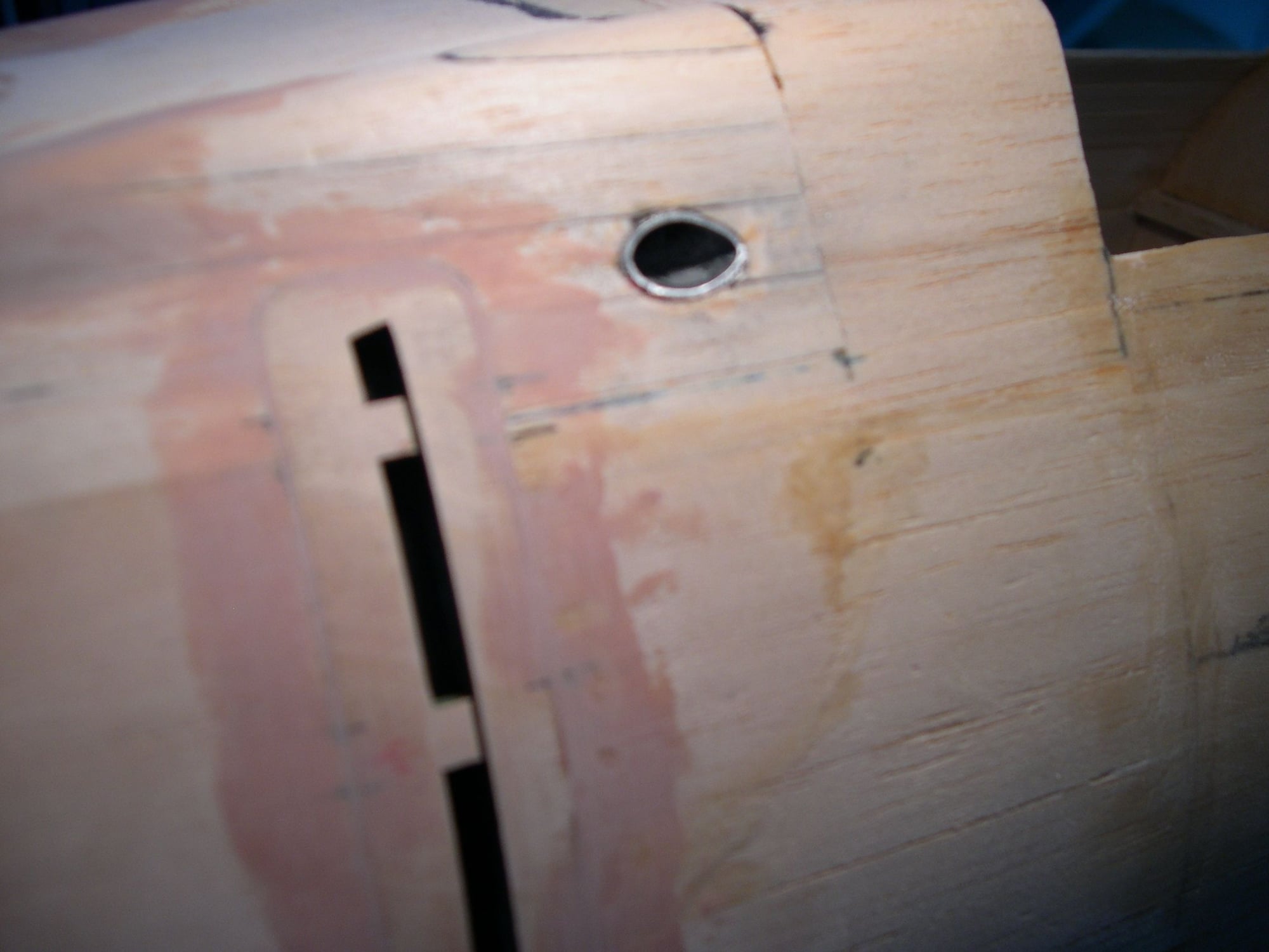
Since the front ply intake piece held the leading edge of the scoop in place, a toothpick was glued to the aft end of the scoop and a hole drilled into the cowl to get the assembly lined up. Since the scoop will eventually get glued to the cowl ( once the foam is removed ), the thin glass sides wouldn't provide much gluing area to keep it in place. I figured a custom-made footing would increase the contact area and strengthen the scoop sides as well. I taped some stretch plastic food wrap in place in the contact area and cut & sanded a triangular "gutter" along the bottom edges of the scoop and troweled in a thick mixture of resin & micro-balloons. Everything got taped in place and if all goes according to plan, this just might work.
Since the front ply intake piece held the leading edge of the scoop in place, a toothpick was glued to the aft end of the scoop and a hole drilled into the cowl to get the assembly lined up. Since the scoop will eventually get glued to the cowl ( once the foam is removed ), the thin glass sides wouldn't provide much gluing area to keep it in place. I figured a custom-made footing would increase the contact area and strengthen the scoop sides as well. I taped some stretch plastic food wrap in place in the contact area and cut & sanded a triangular "gutter" along the bottom edges of the scoop and troweled in a thick mixture of resin & micro-balloons. Everything got taped in place and if all goes according to plan, this just might work.
02-17-2018, 12:50 PM
#232
At this point, the carb scoop was pulled from the clear food wrapped cowl and the resin & micro-balloon mix formed a perfect contact area footing for the scoop to be epoxied to the cowl. This additional glued area also made the base of the scoop much stiffer with no flexing along its width. The ply front plate was hollowed out to the correct outlined shape and the whole works was epoxied in place after some blue foam in the surrounding area was cut away.
Maple cowl mounts were shaped, mortised & epoxied in place. This pre-shaping was done in order for the mounting blocks to disappear, doing their intended job without standing out. Once the cowling was screwed in place, all the remaining blue foam was cut, scraped and wiped out with lacquer thinner as it was no longer needed to position the cowling in place for any further positioning or measuring.
Next, onto a sliding engine mount & tank box design to work with those ply crutch sides (which were originally intended to have maple engine mount beams to glued to them ). More to come. G.
02-25-2018, 03:02 PM
#235
Since this is a vintage kit design ( 1977 ) that used the inner plywood crutch sides w/ maple engine bearers to mount an upright 2-stroke .60 engine, I needed another system to mount my O.S. 81FSa inverted. ( Not only is a 4 stroke more realistic sounding, but the rocker head cover would be hidden by the lower carb intake scoop of this A6M2. I had clipped an article about motor boxes from M.A.N. years ago for my files but a couple of pages were missing. The latest issue of M.A.N. had yet another ( and timely ) article by Gerry Yarrish on just this procedure. Though he didn't have to contend with protruding ply side pieces into the engine compartment, I figured I'd try the basic procedure sliding on the inside. ( I could saw them off down the road if that's what it comes to but I'd like to try using it as a discreet forward cowl mounting system through the "faux" radial.
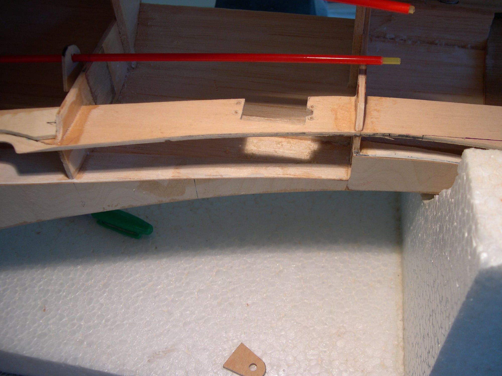
File folder stock templates were drawn & redrawn until everything looked about right and then transferred to the appropriate thickness plys and cut out. Having a laser-cutting machine would have come in real handy in making the tab-locked edges of the inner firewall but it was done old school w/ drill bits, Dremmel saw wheel and sandpaper glued to popsicle sticks. Adding this much plywood to modular house the engine, throttle servo, receiver & battery was making me a little nervous about the wing loading ( especially w/ the already added weight of 3 pontoons ), so I sent it off to Jenny Craig to lose some weight via lightening holes. Weighing the whole works on that engine box, I saved 4/5ths of an ounce. Every little bit helps.
Everything was dry assembled and slid into place and at this point, a back retaining piece will be made to hold everything in the box from sliding out the back end. Though the box will be epoxied together, the back plate and bottom of the servo area will be screwed in place for serviceability. Now to order a flight battery and custom-made spinner so I can continue the madness.
03-15-2018, 11:29 AM
#236
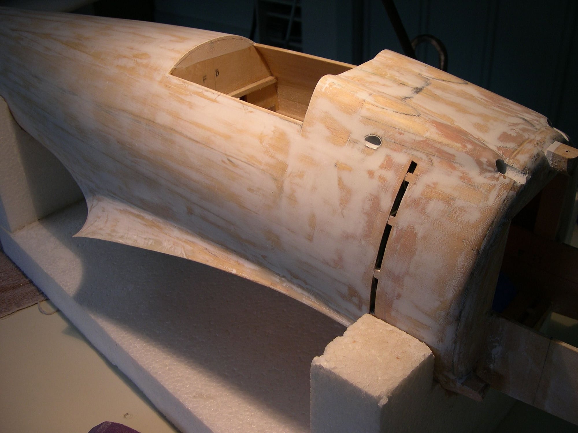
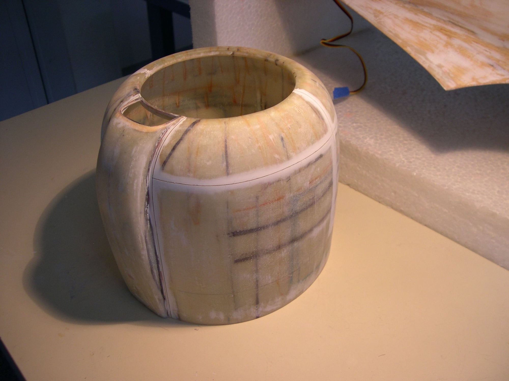
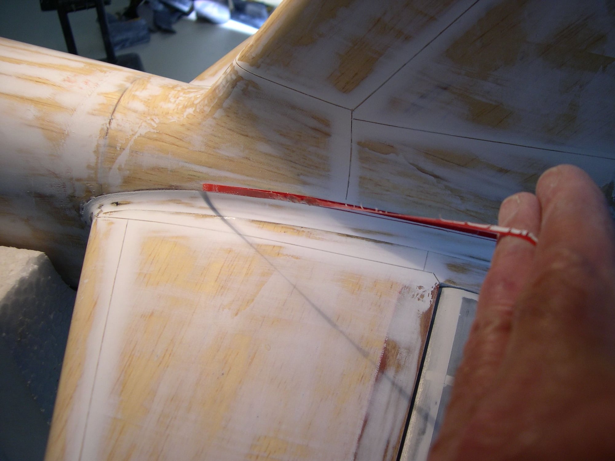
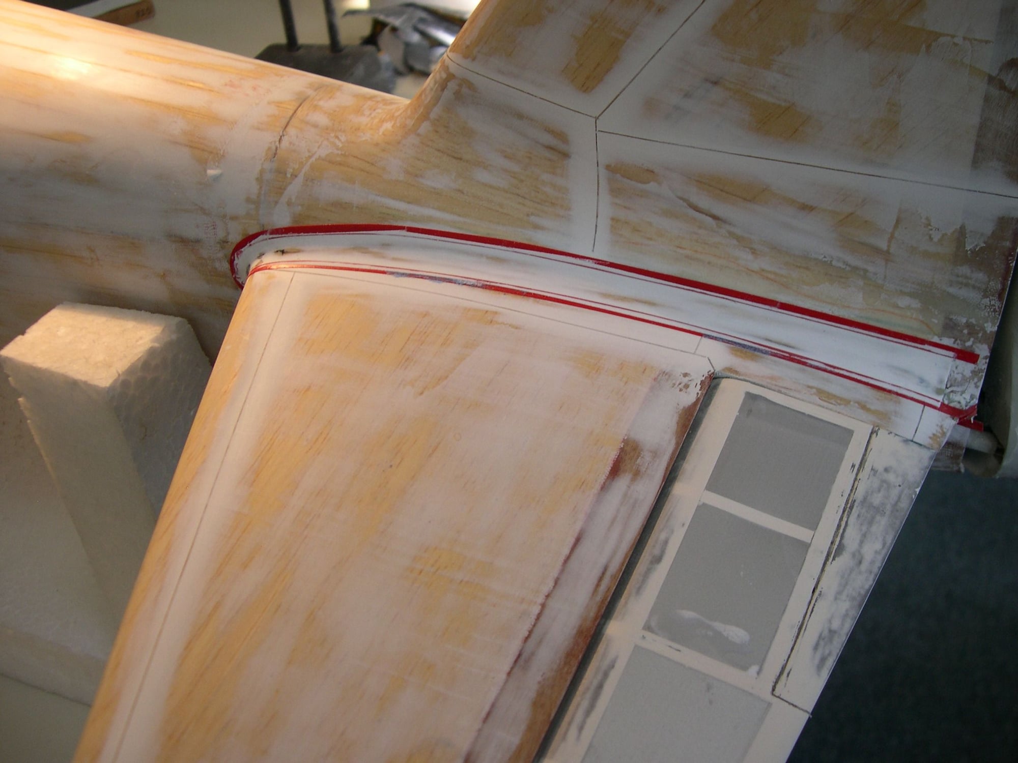
Rather than paint black rectangles on the fuse to simulate cooling slots, I made up a card stock template and transfer all data to 1/64th ply. ( Japanese Micron pens are ideal for this, especially the .005 size as the ink is readily
seen, stays sharp without bleeding into the wood, resulting in fuzzy lines.) Once the outlines were transferred to the fuse using the same pattern for both sides, I had to figure out how best to get an accurate curvature profile of the fuse where vertical bulkhead formers were going to get cemented on the inside. I cut through the intended area with a razor saw and slid a piece of folder stock into it, traced the fuse outline and deducted the thickness of the balsa planking and it was dead perfect.
This outline ( inline?) was transferred to 1/8th ply, all pieces marked to show orientation ( top / bottom, port & starboard ) and a length of chopstick was used to imitate the aluminum horizontal stringers of the real deal. Everything was given a few coats of thin C/A w/ sanding between coats.
Stringers & bulkheads were airbrushed w/ I.G. Klass-Kote. The inner backing, being 1/64th ply was also C/A'd, sanded and airbrushed w/ Testors enamel flat black as there is absolutely no sheen and is well away from glow fuel exhaust. Side bulkheads were glued in place, as well as the backing w/ stringers cut, fitted and glued in. Lastly, the outer skin covers were cemented in and House Bondo applied on the perimeter and sanded flush. ( The inner green side formers cannot be seen in the last shot but do flank the opening nicely, much like the real A6M2.) The black backing can barely be seen, even though a halogen high intensity lamp is about a foot away.
More to come. G.
03-16-2018, 08:58 AM
#238
Thanks Joe! Have you ever seen such foolish masochism?? And I'm not out of the woods just yet. My 3 biggest fears when the big maiden moment comes is, A: Too much wash-out B: Not enough control surface movement and C: Scale elevators being too small to be effective. If any or all of these concerns come to pass, I'll end up with a hydroplane that looks like a Zero ( and performs like a zero )! G.
03-16-2018, 02:28 PM
#239
It definitely looks like quite the endeavor! I understand the concern for rotating off of the water between the weight, scale surfaces, and all that good ol' hydrodynamic drag it'll induce, but with a strong engine and a large enough prop I think you've got a good chance of success.
Oh, and if you're interested in getting that gun sight 3D printed you can post the plans/dimensions here or e-mail them to [email protected]
Oh, and if you're interested in getting that gun sight 3D printed you can post the plans/dimensions here or e-mail them to [email protected]
03-17-2018, 05:11 AM
#241
Thanks! I'm not aware of Marutaka producing a Rufe kit on 1/7th scale. That would have made things so much easier for me. My friend Teddy "Chistech" Brito bought a Marutaka Rufe but we had to scale up the plans until the fuselage profile matched the .60 size Zero kit I'm working from, then we were assured the pontoon(s) were sized correctly for my 1/7th scale A6M5 kit. At any rate, I'm sure you'll have a faster / easier build than what I'm putting myself through. If you look at the elevator shape on your Rufe plans and then compare that to the scale outline of my elevators at the beginning of my build, you'll see how much larger ( and without a true scale outline ) the Marutaka kit has. Now you know why I have my apprehensions about how my project will fly. In summation....... keep it a "straight" build. G.
03-17-2018, 06:33 AM
#242
Thanks Joe! Have you ever seen such foolish masochism?? And I'm not out of the woods just yet. My 3 biggest fears when the big maiden moment comes is, A: Too much wash-out B: Not enough control surface movement and C: Scale elevators being too small to be effective. If any or all of these concerns come to pass, I'll end up with a hydroplane that looks like a Zero ( and performs like a zero )! G.
03-17-2018, 01:49 PM
#243
I figured the easiest way to replicate the 30 cal. shell chutes was to reshape aluminum streamlined tubing into a wider cross section, mark the locations on the fuse and grind away the balsa with a carbide rasp on a Dremel.
I plugged the inside bottom end of the chutes w/ balsa, inserted them to the proper depth and trace the fuse side onto the excess sticking out, pulling them out for cutting and reinsert. They were glued in place with thin C/A and anything left proud of the fuse side were carefully filed and sanded flush. Another eye candy job finished in a relatively short time. G.
03-26-2018, 11:26 AM
#244
Hello Gang, Gerry D. here, just letting you know I haven't been idle during this past week or so, merely going through the less-than-interesting process of installing servos in the wing for ailerons, flaps and pontoon rudder. No need to bore you with this portion of the saga. Once finished, assuming a customized spinner hasn't arrived yet, I'll be getting into making panel lines, etc. which will be photographed & posted. Hang in there. G.
04-27-2018, 11:59 AM
#245
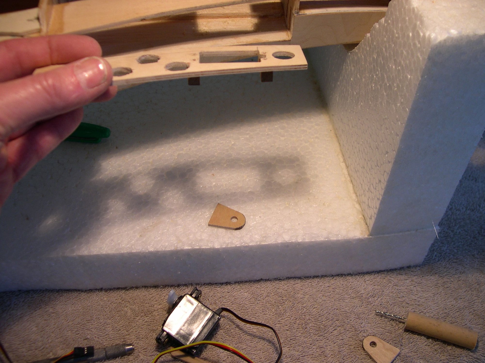
Something as mundane as servo installation doesn't warrant any light to be shed on it but in this situation, a little forethought and some ingenuity would come in handy. Every bit of radio gear had to be shoved as far forward as possible to decrease nose weight and lessen the overall wing loading. With the motor box taking up enough real estate and the water rudder servo as yet to be installed right behind it on the upper wing surface near the main spar, the only slick place to mount the elevator and rudder servo was on ( in ) the main fuse "crutch" just aft of the intended water rudder servo location on top of the wing.
Photo 1: Inner crutch servo cut-out for elevator made and mounting holes marked. ( Note ply bracket slid in place further aft, to be cemented in place when everything is in position & lined up.
2: Matching ply sandwich piece made and ready to be cemented in place on backside of crutch. ( Note maple blocks already cemented in place, pre-drilled and threaded.) Enough meat was taken out of the crutch to
begin with so something had to go back. ( Lightening holes drilled in to help minimize weight. )
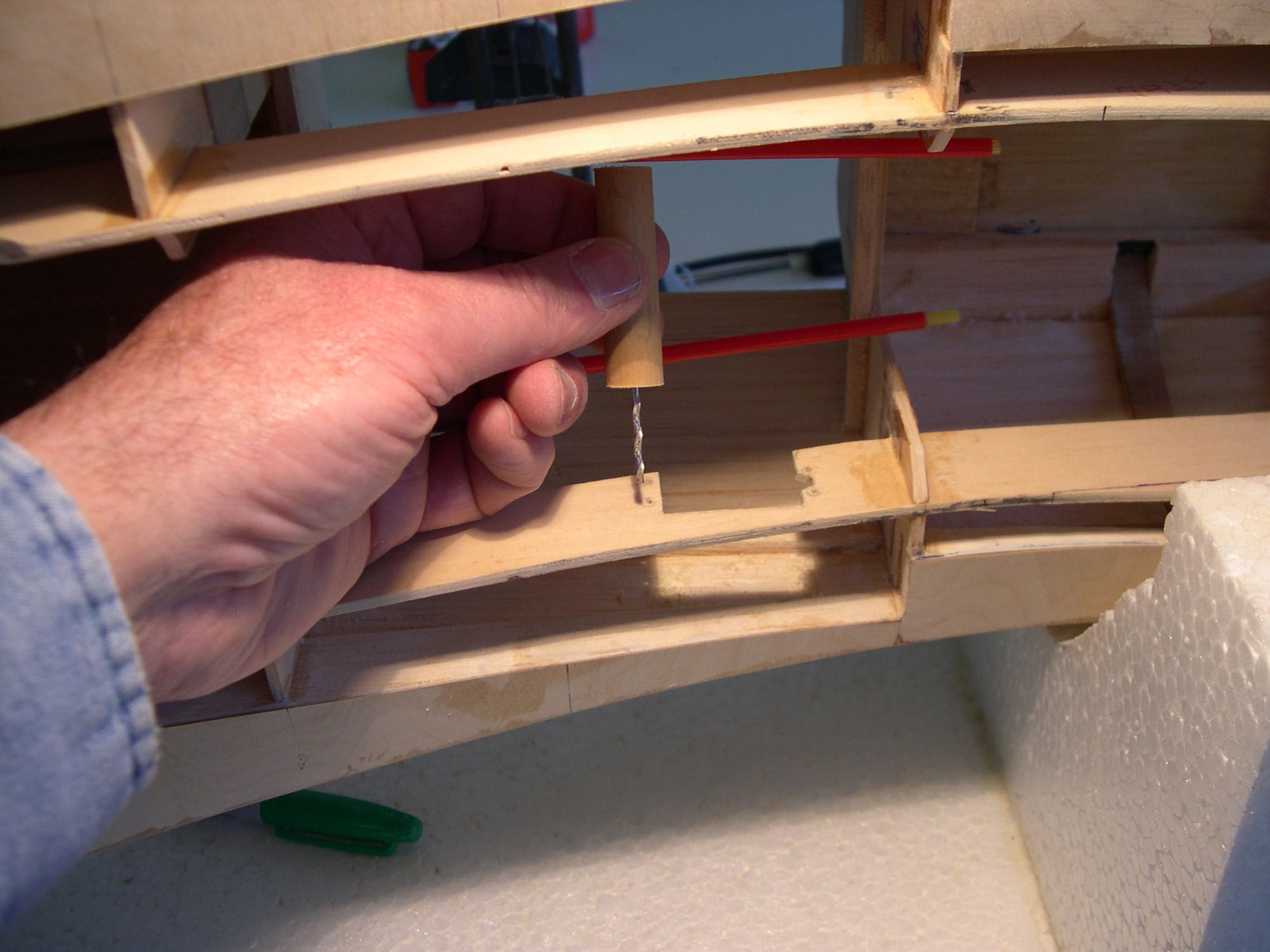
3: I couldn't so much as fit a pin-drill holder in such a narrow space so I drilled a short length of birch dowel, tapped a bit into it and hand-drilled the servo mounting holes.
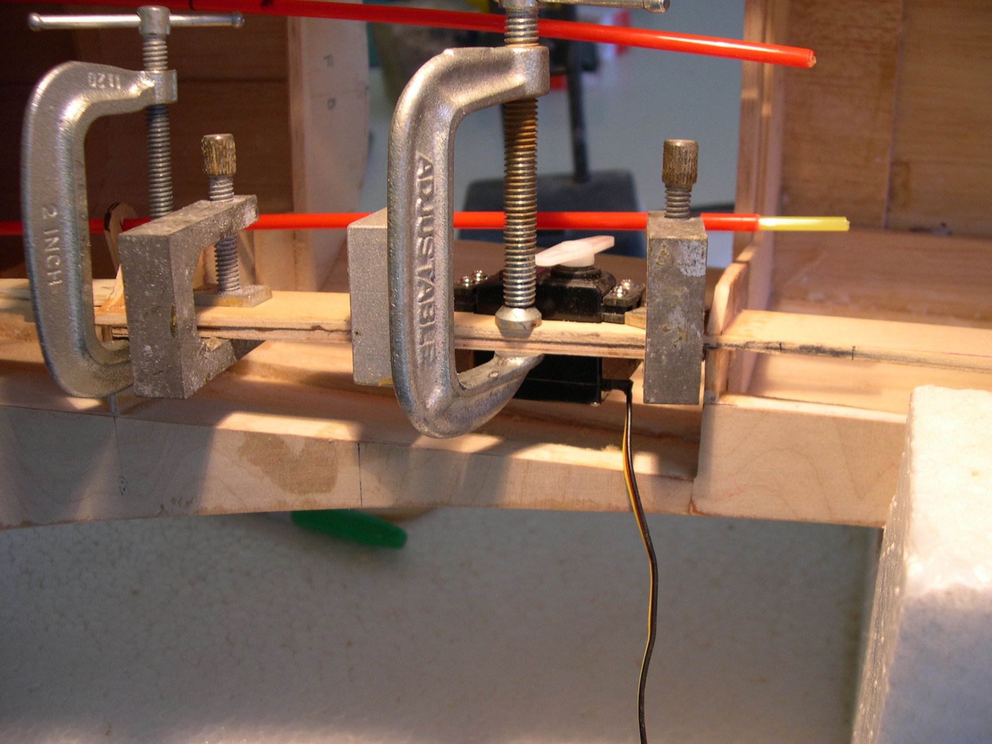
4: With the reinforcement piece carefully coated in epoxy, the servo was dropped in, raised up slightly to slide the assembly behind the crutch and the servo screws tightened to line everything up and draw the
assembly together. At that point, it was clamped and left to dry.
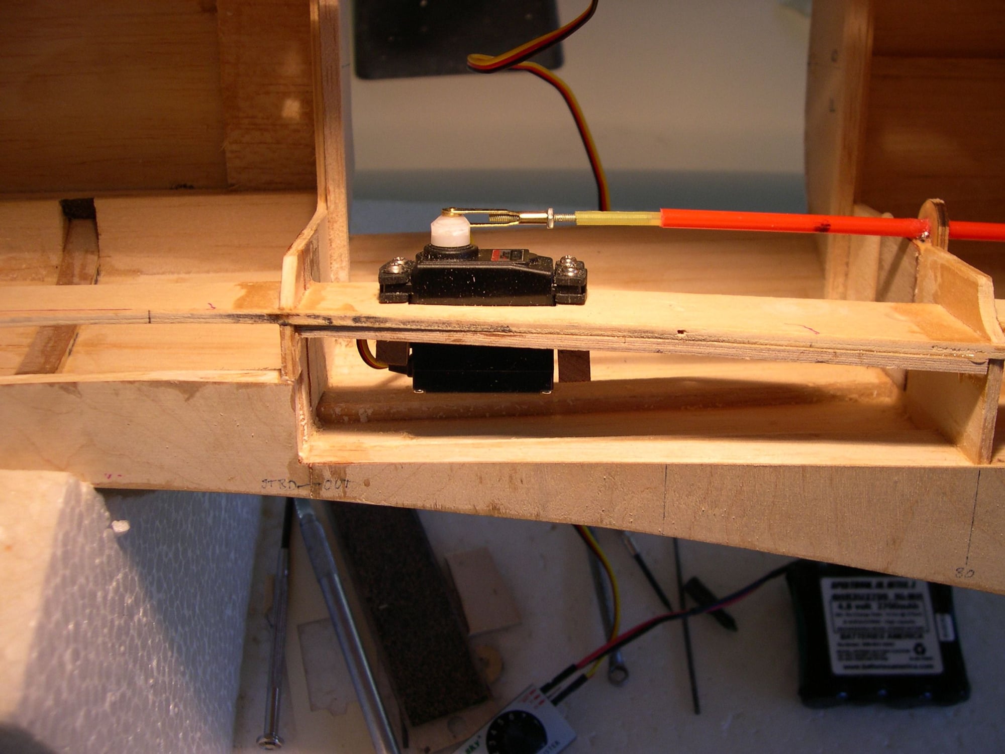
5: Finished installation. Procedure repeated on starboard crutch for rudder servo.
04-28-2018, 03:47 PM
#248
My description of "tapped" was quite literal and not the presumed interpretation. Once I used a particular sized drill bit to make the receiving hole in the short length of
dowel, I removed the drill bit from my DeWalt, placed the bit point down into a block of wood, slide the hole of the dowel over the drill's back end and lightly "tap" it down until the dowel moved no further. There's enough of a friction fit to keep the drill bit from spinning freely inside the dowel when the hand drilling begins. Afterward, the bit is removed from the dowel using pliers. Sorry if I misrepresented myself. G.
dowel, I removed the drill bit from my DeWalt, placed the bit point down into a block of wood, slide the hole of the dowel over the drill's back end and lightly "tap" it down until the dowel moved no further. There's enough of a friction fit to keep the drill bit from spinning freely inside the dowel when the hand drilling begins. Afterward, the bit is removed from the dowel using pliers. Sorry if I misrepresented myself. G.
08-06-2018, 05:25 PM
#250
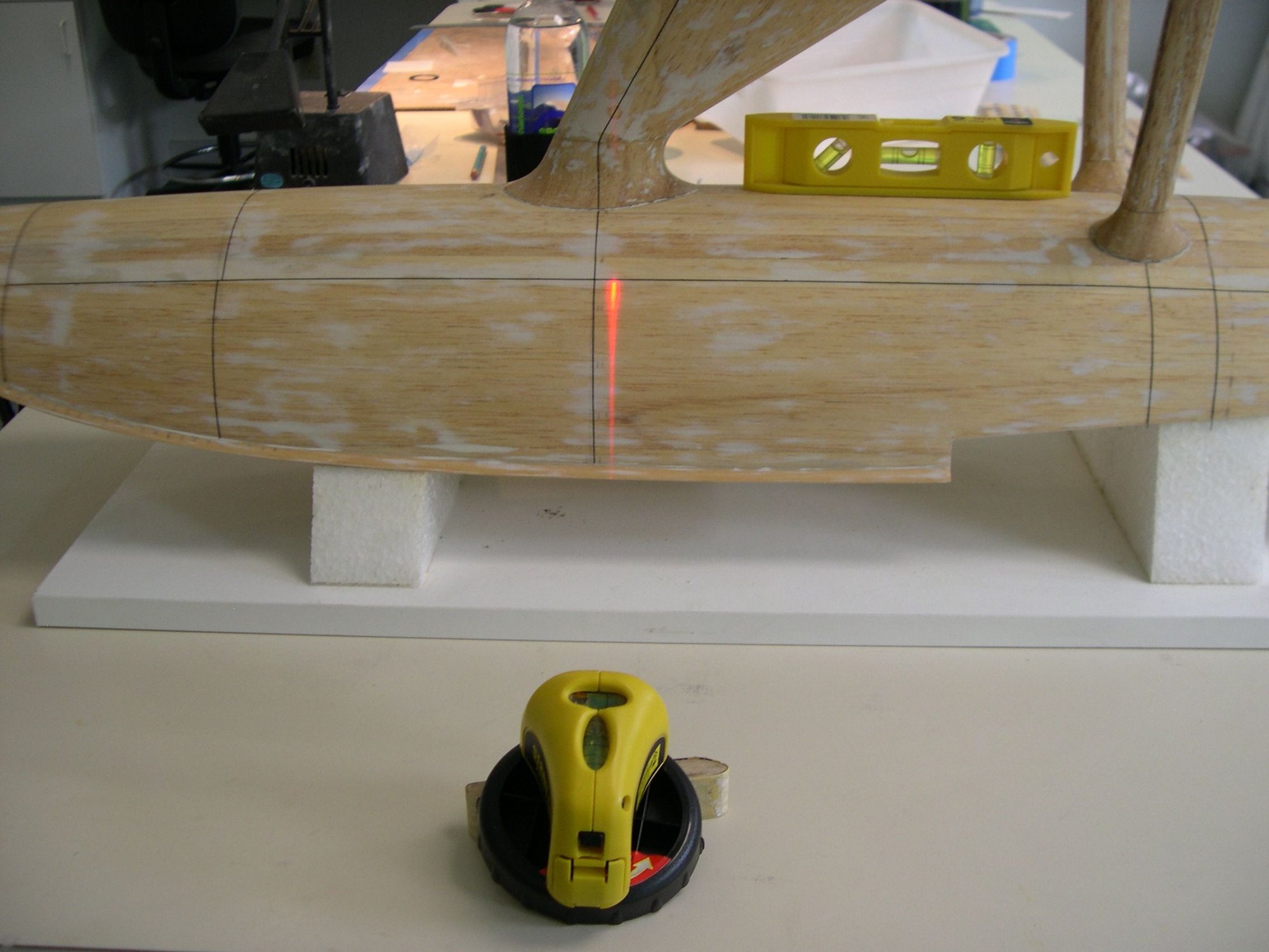
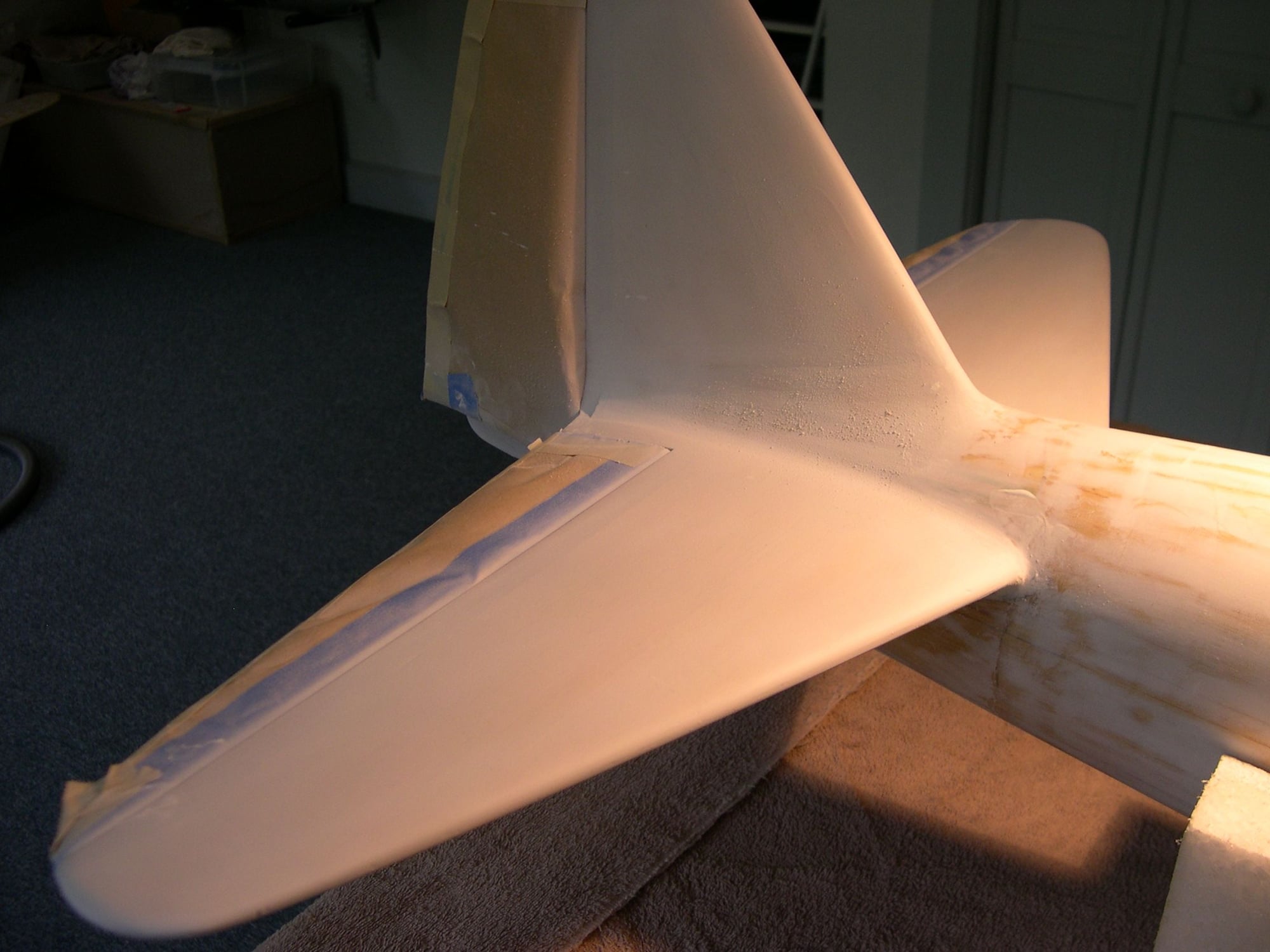
Hey gang, back again despite work and heat......two elements that get in the way of completing this project. Though I was hoping to get everything done in time for my club's annual John Nicolaci Memorial Float Fly at Mary's Pond in Rochester, Ma. on Aug. 18th, it just could not be ready in time. With what needs to be done to finish this project, it will be a two-pronged approach. It will most likely be airworthy by mid Oct., the detailed, all-out finished product will be realized only after a bare bones outfitting for flight trials. That essentially means a painted plane, no cockpit detail or pilot, no weathering or "eye candy" detailing. That will all come after sea trials and ultimately flight trials to see if it is pilot friendly or a real bear.
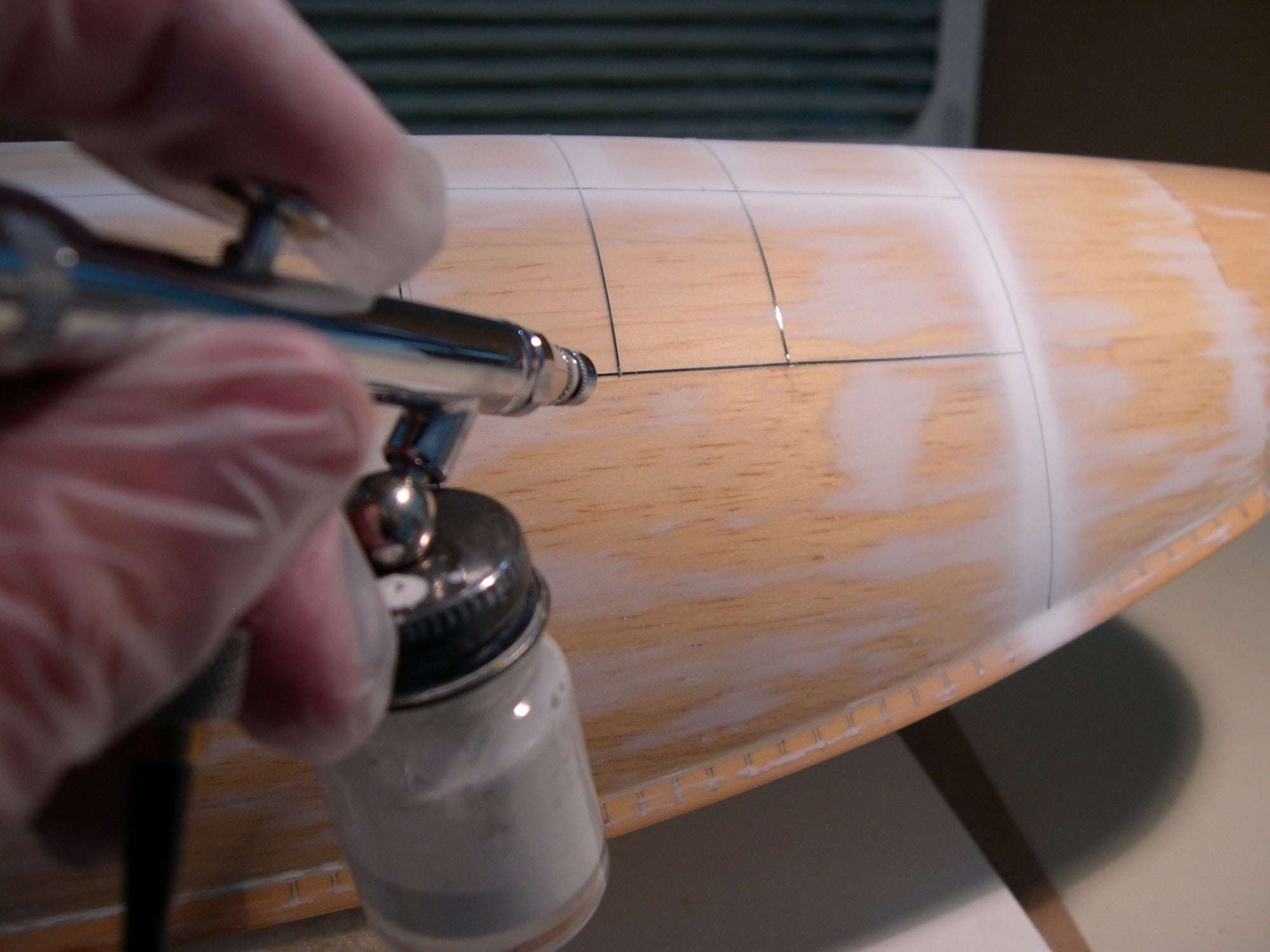
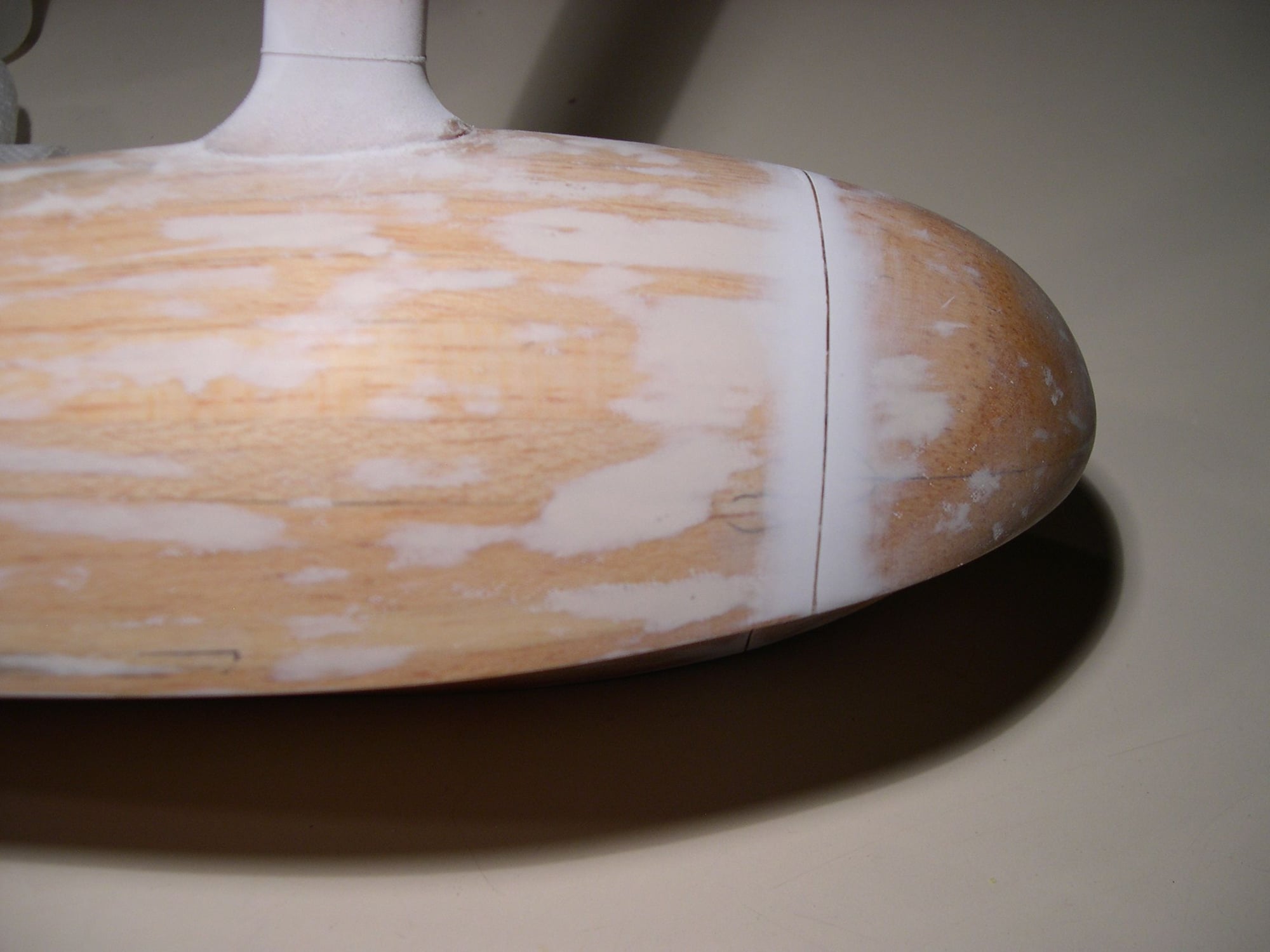
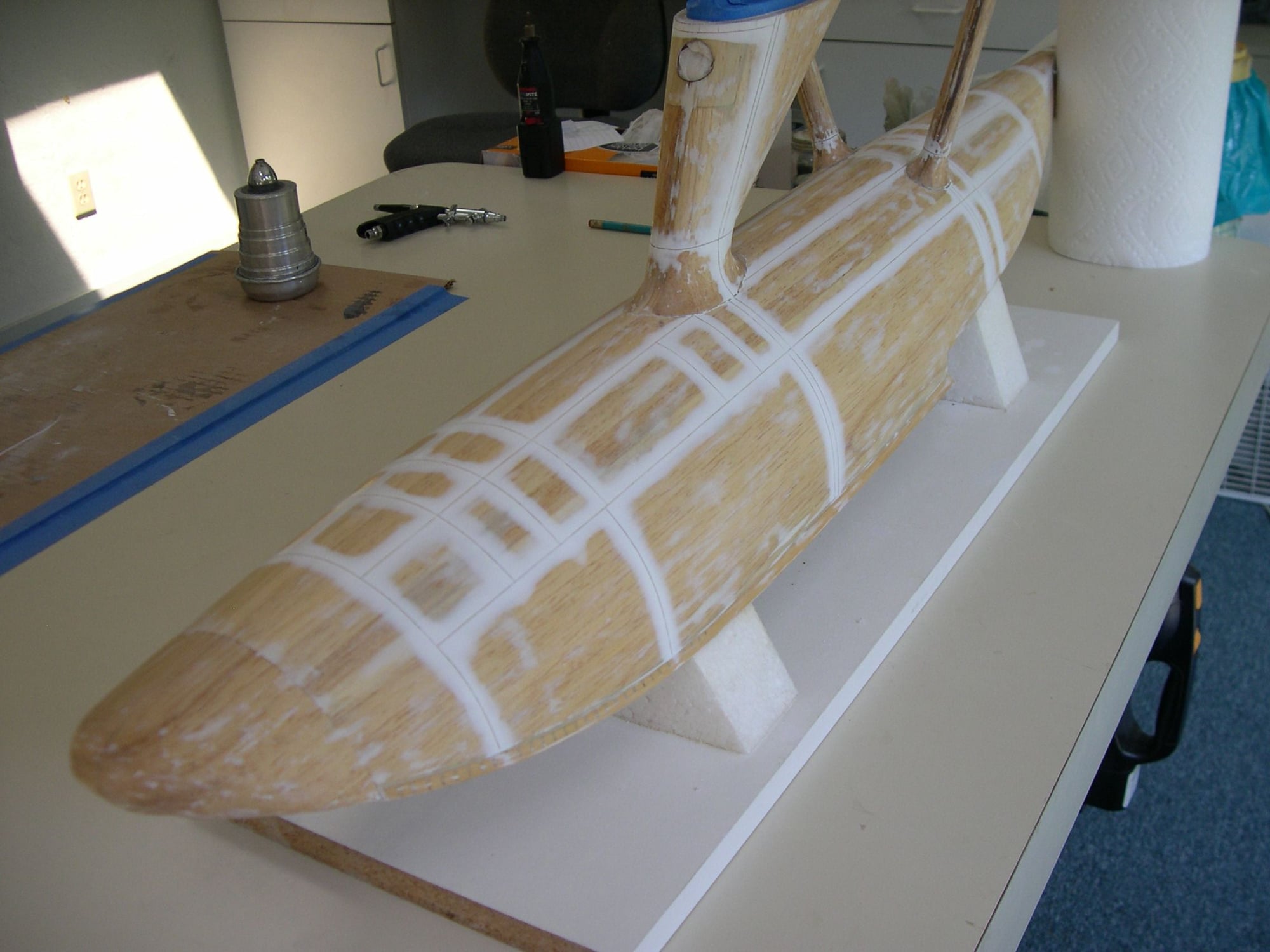
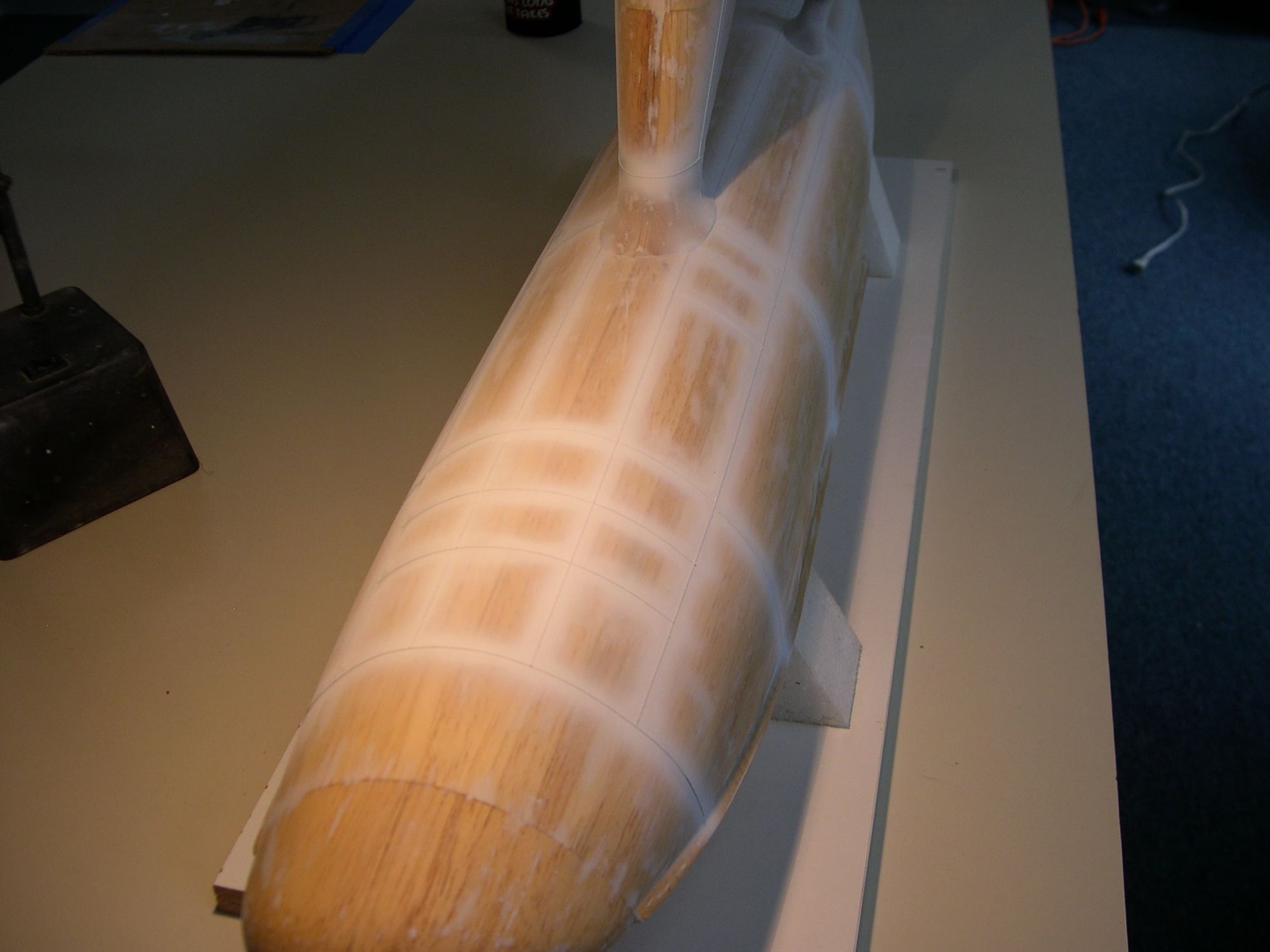
The enclosed photos show a glassed, primed & ready fuse, as well as the 1/64th panel taping w/ epoxy primer, sanded away to reveal panel lines. Problem is when painted, all that work is virtually invisible and at some point, masking off the side walls of the joint lines and spraying a slightly darker shade of JN grey to make these panel lines a bit more pronounced is in order, at least in my estimation. More to come. G.
BTW: My wife ( who does these postings ) would like any help in figuring out how to post these photos in a smaller format as these are much bigger than need be. She claims " They keep changing things around on me!" Thanks.