


Top-Flite 1/5th F4U Corsair ARF Group Build and modification thread
 08-19-2019, 03:36 PM
#676

Join Date: Jul 2017
Location: Just East of Cleveland Ohio
Posts: 51
Likes: 0
Received 1 Like
on
1 Post
Could you please post a pic of how you did this? I have the Robart electric retracts, and the tail sits awfully close to the ground. I am worried I would rip off the tailwheel doors.
Thx! DSA
 08-19-2019, 09:07 PM
#677


The Robart tail retract can be modified with a spacer to increase the length of the gear. Just loosen the set screws and place a bushing in there about 6mm thick or maybe more if you can. The trailing edge of the retract bay might interfere with the tire so watch for that.
I’ll post pics of mine later...
I’ll post pics of mine later...

 09-02-2019, 03:24 PM
#682
Join Date: Dec 2014
Posts: 26
Likes: 0
Received 0 Likes
on
0 Posts
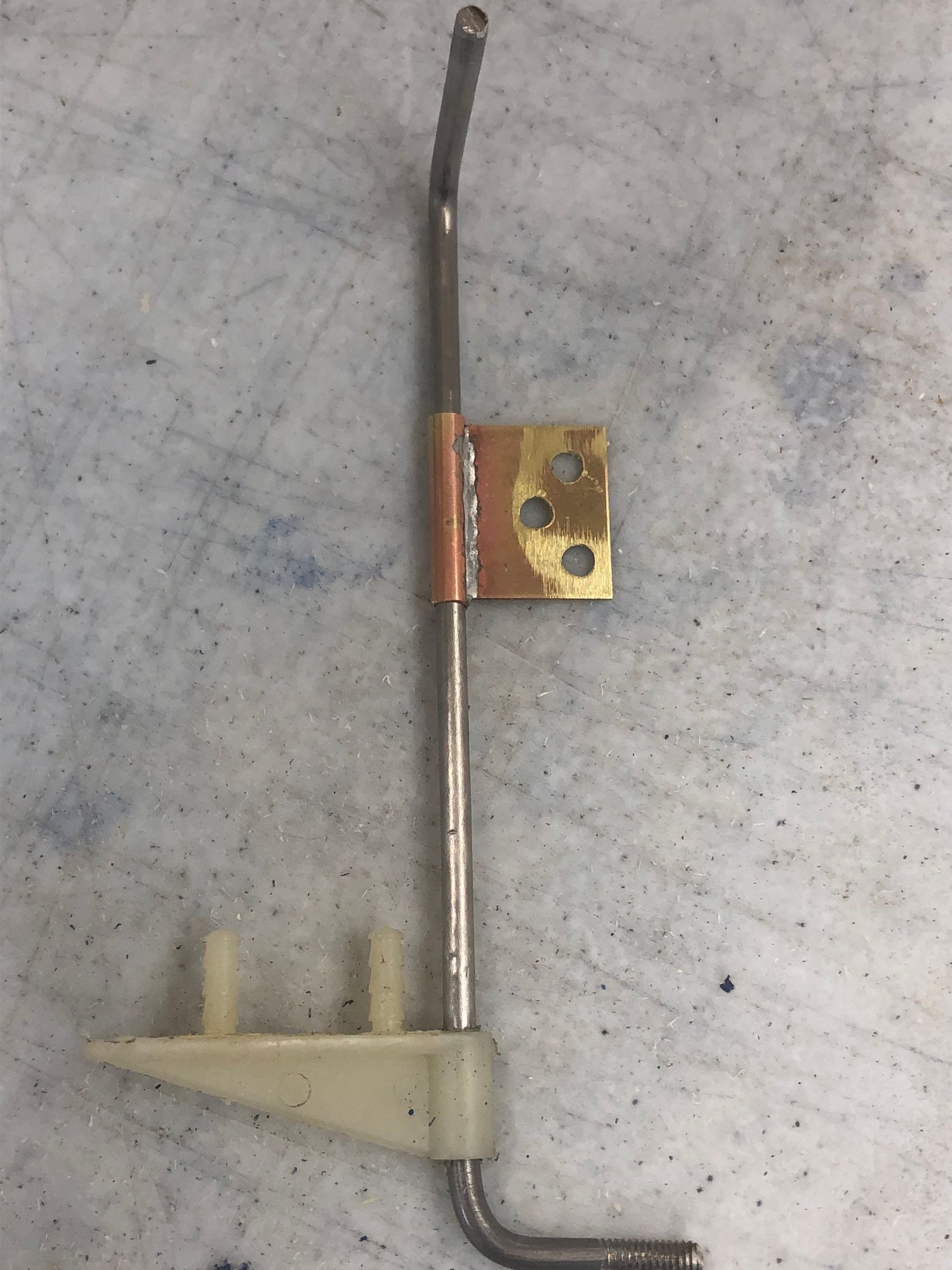
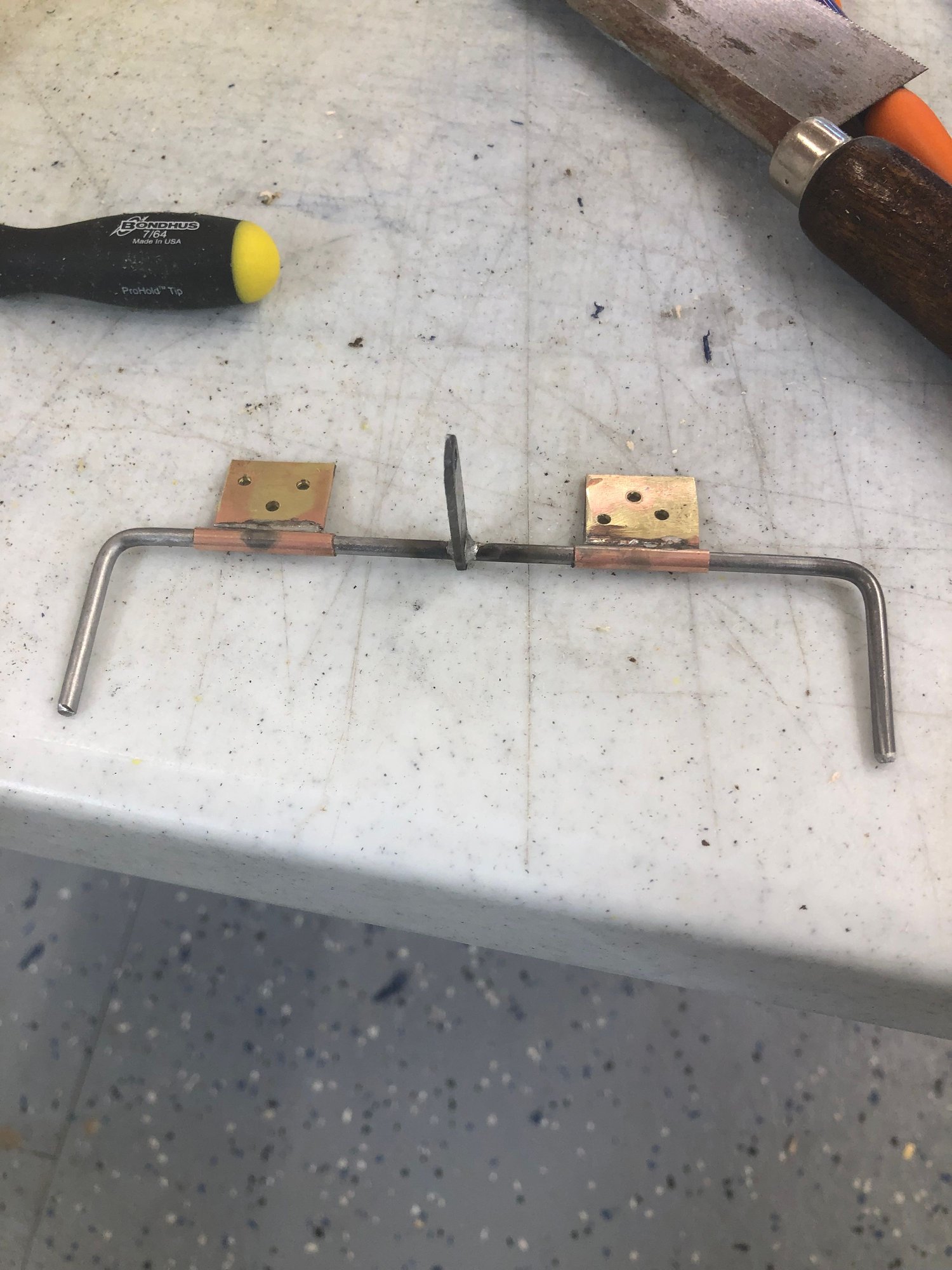
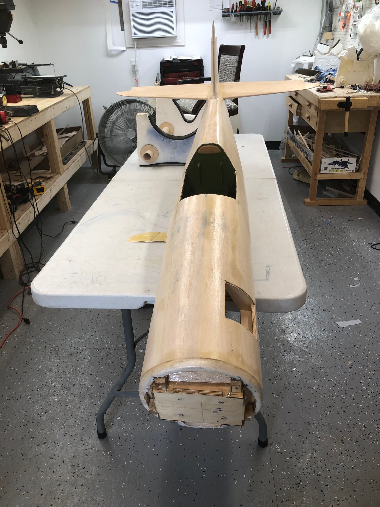
Made new torque rods for the rudder and elevator out of music wire to fix the flex problem in the control surfaces
also made the elevator a common rod for 1 servo
also added new hard wood blocks to the rudder and both elevator half�s
09-02-2019, 08:23 PM
#684
Dusturbd that elevator linkage you made is a good idea but I would be concerned with relying on that solder joint to take the torque load.
A better design would be to make the wire loop and twist so it’s one continuous wire. Then solder a couple plates or a tube over the center section to box it in. This way is bullet proof and will not fail. Just a thought...
A better design would be to make the wire loop and twist so it’s one continuous wire. Then solder a couple plates or a tube over the center section to box it in. This way is bullet proof and will not fail. Just a thought...
09-03-2019, 06:07 AM
#685
Join Date: Mar 2011
Location: Wilmington, NC
Posts: 40
Likes: 0
Received 0 Likes
on
0 Posts
I did try that at one store, took a roll of monokote and the guy put the meter on it but he could not get a reading, he thought because of the flat color, I wonder if I should have him scan the underside of the covering as it is glossier then the outer finish
09-03-2019, 12:36 PM
#686
Join Date: Dec 2014
Posts: 26
Likes: 0
Received 0 Likes
on
0 Posts
Dusturbd that elevator linkage you made is a good idea but I would be concerned with relying on that solder joint to take the torque load.
A better design would be to make the wire loop and twist so it�s one continuous wire. Then solder a couple plates or a tube over the center section to box it in. This way is bullet proof and will not fail. Just a thought...
A better design would be to make the wire loop and twist so it�s one continuous wire. Then solder a couple plates or a tube over the center section to box it in. This way is bullet proof and will not fail. Just a thought...
that is a silver solder joint I have used that same setup many times since the early 90�s and have never had 1 fail not to say it can�t or won�t but I have had good luck with them
09-04-2019, 08:18 AM
#688
Join Date: Mar 2011
Location: Wilmington, NC
Posts: 40
Likes: 0
Received 0 Likes
on
0 Posts
09-04-2019, 04:53 PM
#689
Join Date: Jul 2017
Location: Just East of Cleveland Ohio
Posts: 51
Likes: 0
Received 1 Like
on
1 Post
Thanks Chris and Lifer,
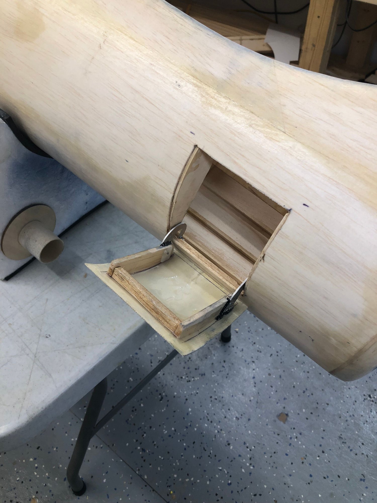
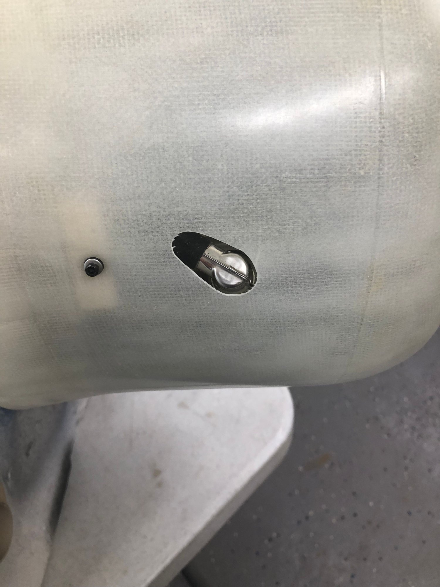
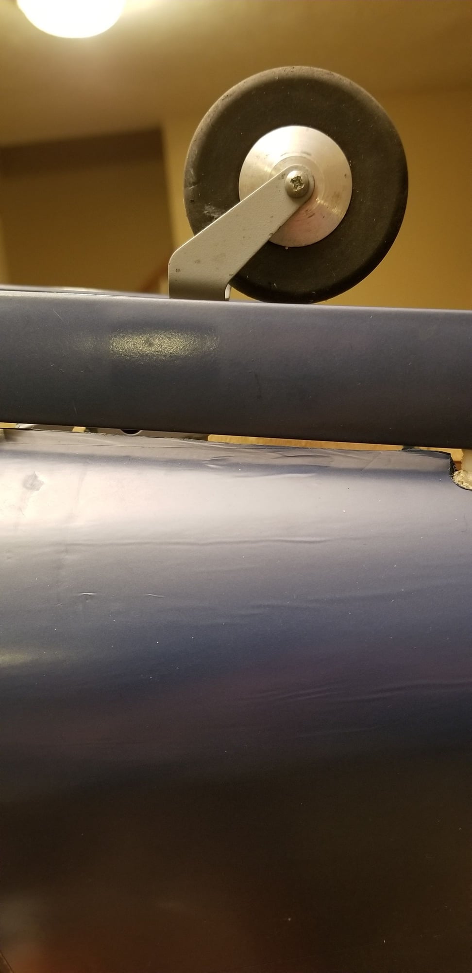
I was able to add a couple collars as spacers, but stripped the darned grub screw on the steering horn in the process. The shaft is at its limits, flush on top and bottom to the respective steering arm and wheel fork.
Upon retracting, there is probably another 1 cm or so clearance between the wheel and aft margin of retract bay, so I might just try a slightly longer 4mm shaft to push the wheel out further.
What do you think, good enough for grass, or get a longer shaft and move it out a little more??
Cheers, DSA
09-04-2019, 05:06 PM
#690
Join Date: Jul 2017
Location: Just East of Cleveland Ohio
Posts: 51
Likes: 0
Received 1 Like
on
1 Post
And while we are at it, I should clarify, I stripped the -head- of the grub screw, not the threads. I tried a 3mm and 4mm size, but Robart must have used imperial ones. Anyone know what size grub I need to find for the steering arm??
Thx
Thx
09-04-2019, 05:48 PM
#693
@DSA, that looks better and should be an improvement on grass. Occasionally if I run over a tough weed I’ve had a door linkage pop off or lost or a door hinge damaged.
On my plane I need to re-relocate my rudder servo so I can drop in the H9 Corsair retract. I put the servo above the retract and wheel where there’s room and that was ok for the Robart gear but not for the taller H9 gear.
On that set screw you can use a thin cut off disc and slot it. Then use a small screw driver to unscrew it. The cutting heat will help loosen it too.
09-11-2019, 03:41 PM
#694
Join Date: Jul 2017
Location: Just East of Cleveland Ohio
Posts: 51
Likes: 0
Received 1 Like
on
1 Post
Hey fellas,
I am at the point of trying to get cg right. Dry, inverted, gear retracted, I tried 146 mm as suggested in manual and was way tail heavy. With an additional 1 lb lead up front, I was able to get it balanced but at 155mm. Thats all the lead I have at the moment.
I am curious where you have your cg's and if 155mm is still really out of whack.
Cheers, DSA
PS. If you need a set screw for the tail gear, I found out from robart they are 6-32 Thread, 1/8" . Mine were beyond salvage. Picked some up from from McMaster.
09-12-2019, 03:27 PM
#696
Join Date: Jul 2017
Location: Just East of Cleveland Ohio
Posts: 51
Likes: 0
Received 1 Like
on
1 Post
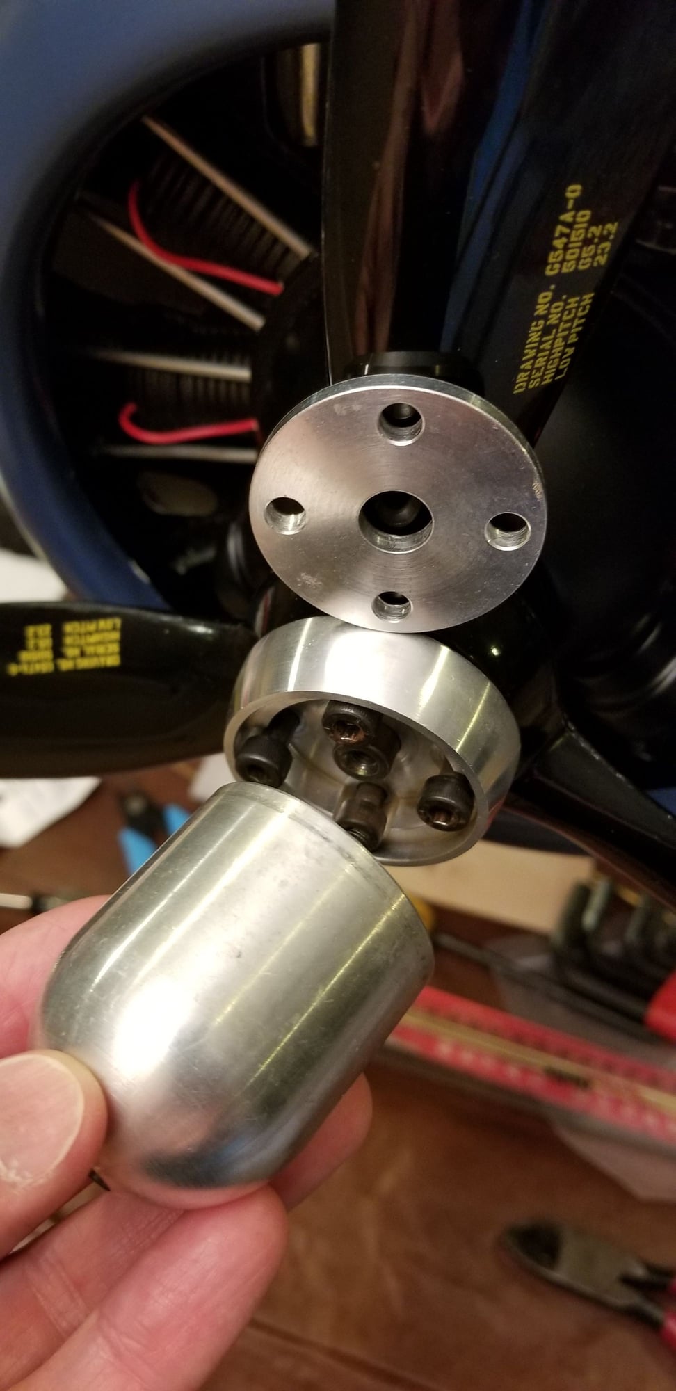
Washer or drill guide??
Hey, got it balanced nicely at 146mm with about 1.5lbs upfront and reshuffling the batteries! (Don't you love mixing metric with imperial?? lol)
Can anyone confirm if this top structure is a necessary prop washer, or just a drill guide, as it doesn't seem thick enough to be a drill guide??
Thx
09-24-2019, 01:05 PM
#700
Brief video of my Corsair taken by a buddy with his cellphone today. I damaged the plane last year following a flameout, repaired last Winter, and just got around to re-trimming it to my preferences. EME 60, Mejzlik 23x8, and a stock build. A genuine pleasure to fly!
https://www.youtube.com/watch?v=GYLo...eature=youtu.b
https://www.youtube.com/watch?v=GYLo...eature=youtu.b

