


TF FW190 GIANT ARF

 03-11-2013, 07:20 PM
#1252
ORIGINAL: SteveD-RCU
I flytailies has a new 1/5 FW190 decal kit out....http://www.iflytailies.com/store/decals/
I flytailies has a new 1/5 FW190 decal kit out....http://www.iflytailies.com/store/decals/
Those look good. They are water slides so make sure to shoot clear over them.
03-11-2013, 08:18 PM
#1253
ORIGINAL: SrTelemaster150
Why would a jackscrew be unreliable?
If you have a servo speed function on your Tx, that's an viable option. Many of us do not have that option.
I have fabricated a sliding shoe W/a guide & installed them in the fuselage. Since this is prototype work, I'm going to make a few minor chages before posting the results..
ORIGINAL: n8622t
I think I'll just use a servo and slow it down with my radio...... Jackscrew looked a little unreliable
I think I'll just use a servo and slow it down with my radio...... Jackscrew looked a little unreliable
If you have a servo speed function on your Tx, that's an viable option. Many of us do not have that option.
I have fabricated a sliding shoe W/a guide & installed them in the fuselage. Since this is prototype work, I'm going to make a few minor chages before posting the results..
03-12-2013, 02:34 AM
#1254

My Feedback: (2)

Join Date: Jan 2002
Location: Sault Ste Marieont, CANADA
Posts: 946
Likes: 0
Received 2 Likes
on
2 Posts
ORIGINAL: tfarmer96
Those look good. They are water slides so make sure to shoot clear over them.
ORIGINAL: SteveD-RCU
I flytailies has a new 1/5 FW190 decal kit out....http://www.iflytailies.com/store/decals/
I flytailies has a new 1/5 FW190 decal kit out....http://www.iflytailies.com/store/decals/
Those look good. They are water slides so make sure to shoot clear over them.
03-12-2013, 07:09 AM
#1255
Senior Member

I've finished my shoe & guide for the forward located electric actuator to operate the TW retract W/O torquing the pushrod.
Since this is a 1st prototype, changes were made along the way.
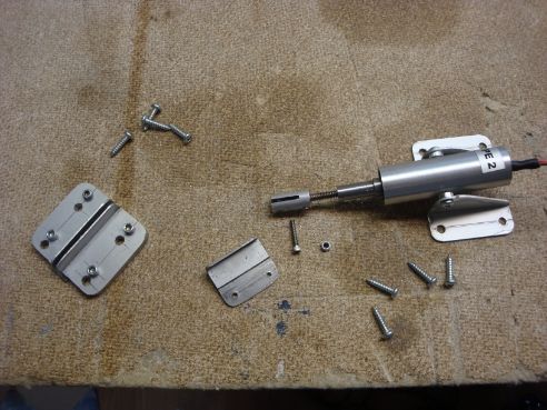
The 1st picture is is of the pieces I made from .040" extruded aluminum angle. .040" is about ideal. .030' would probably be OK but that would be minimum for strength & anything over .040 would be heavier than neccesary.
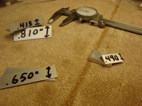
The guide plates (upper left) had the vertical leg reduced from .415 to .315. The .810 dimention was just the original extrusion dimension & that was about right so it was not altered. The vertical leg of the shoe doubler (middle right) was reduced from .490" to .360" to allow clearance for the actuator clevis. The finished shoe hieght is the same .810" as the extrusion.
The guide plate doublers (lower left) are sized so that when applied flush W/the outside edge of the guide plates, there will be clearance to allow the shoe foot ample clearance.
The final lengths for the guide was 1 1/2" & the shoe ended up @ 1".
Glue & clamp the shoe doubler to the shoe.
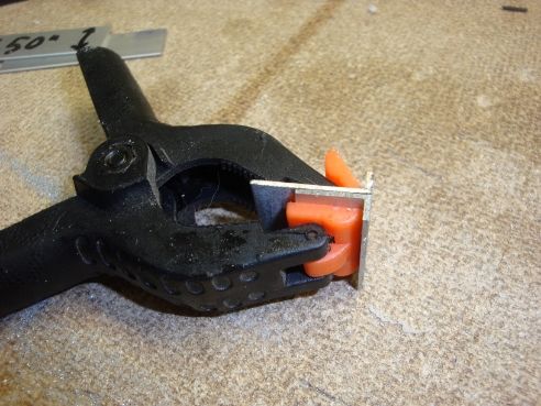
Since this part will be relying on the adhesive alone, it would be best to use something like JB Weld. Make sure the base legs are flush.
Glue & clamp the doublers to the guide plates.
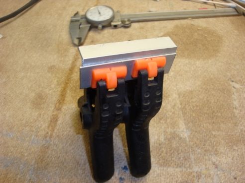
The outer edges should be flush & there should be clearance for the shoe base leg to slide. Since these parts will be secured W/screws later, 5-miute epoxy would be OK.
Glue the completed guides to some .060" aluminum plate W/5-minute epoxy.
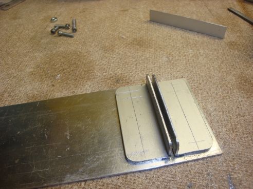
Use the shoe W/doubler to assure slide clearance. Do not use ecess epoxy. You do not want epoxy to squeeze into the slot for the shoe. Just use enough to secure the assembly until screws can be applied. Leave a ledge on @ least 1 end for ease of shoe insertion on the finished product.
Since this part will be worked W/power tools, (heat will be an issue) secure both sides of the guide plates W/4-40 screws. Sand the bottom of the screws flush on a disc/belt sander W/a fine grit disc/belt. Grind all edges flush except for a small ledge @ the end of the guide slot. Radius all corners.
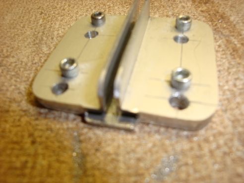
The shoe should be worked by hand tools to prevent heat from affecting the glue bond. Radius all edges of the shoe & file the base thickness (if needed) to allow the shoe to slide freely. Place the file flat on a non-slip surface & work the shoe base across the file to evenly reduce the thickness of the shoe base as needed for a free sliding fit W/O excess clearance.
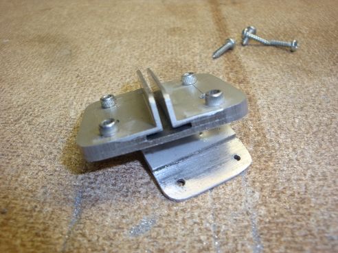
Drill a 5/64" hole in one end of the shoe for the clevis bolt & a 1/16" hole in the other end for a pushrod clevis. The guide plate should have 4 holes drilled for srews to anchor the plate to the servo deck.
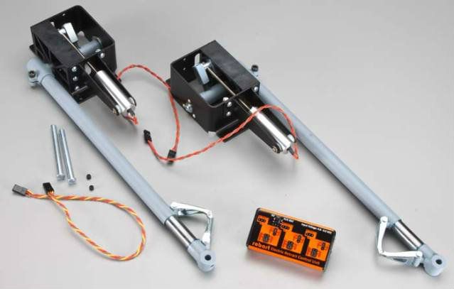
Here are the finished shoe & guide plate along W/the actuator modified as described in the previous post.
Here is the entire assembly mocked up on the bench to show the straight line relationship.
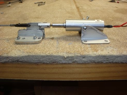
On my fuselage, the distance from the deck to the TW retract pushrod is approximately 5/8" & all the dimensions reflect that value.
In the next post I will illustrate the installation in the fuselage.
The actuator & mount weigh 1.58oz, just .02oz more than a standard 60oz in servo. The shoe & guide W/screws weigh .71oz. This complete set-up weighs only .73oz more than a standard 60oz in servo.
Even if the TF Fw 190 A ARF would allow the actuator to be installed integral W/the TW retract, (it won't) the weight savings in the tail (1 6 oz) by this set-up would reduce any ballast needed in the nose substantially. The forward location is very near the CG so the nose ballat savings would be about 7oz.
Since this is a 1st prototype, changes were made along the way.
The 1st picture is is of the pieces I made from .040" extruded aluminum angle. .040" is about ideal. .030' would probably be OK but that would be minimum for strength & anything over .040 would be heavier than neccesary.
The guide plates (upper left) had the vertical leg reduced from .415 to .315. The .810 dimention was just the original extrusion dimension & that was about right so it was not altered. The vertical leg of the shoe doubler (middle right) was reduced from .490" to .360" to allow clearance for the actuator clevis. The finished shoe hieght is the same .810" as the extrusion.
The guide plate doublers (lower left) are sized so that when applied flush W/the outside edge of the guide plates, there will be clearance to allow the shoe foot ample clearance.
The final lengths for the guide was 1 1/2" & the shoe ended up @ 1".
Glue & clamp the shoe doubler to the shoe.
Since this part will be relying on the adhesive alone, it would be best to use something like JB Weld. Make sure the base legs are flush.
Glue & clamp the doublers to the guide plates.
The outer edges should be flush & there should be clearance for the shoe base leg to slide. Since these parts will be secured W/screws later, 5-miute epoxy would be OK.
Glue the completed guides to some .060" aluminum plate W/5-minute epoxy.
Use the shoe W/doubler to assure slide clearance. Do not use ecess epoxy. You do not want epoxy to squeeze into the slot for the shoe. Just use enough to secure the assembly until screws can be applied. Leave a ledge on @ least 1 end for ease of shoe insertion on the finished product.
Since this part will be worked W/power tools, (heat will be an issue) secure both sides of the guide plates W/4-40 screws. Sand the bottom of the screws flush on a disc/belt sander W/a fine grit disc/belt. Grind all edges flush except for a small ledge @ the end of the guide slot. Radius all corners.
The shoe should be worked by hand tools to prevent heat from affecting the glue bond. Radius all edges of the shoe & file the base thickness (if needed) to allow the shoe to slide freely. Place the file flat on a non-slip surface & work the shoe base across the file to evenly reduce the thickness of the shoe base as needed for a free sliding fit W/O excess clearance.
Drill a 5/64" hole in one end of the shoe for the clevis bolt & a 1/16" hole in the other end for a pushrod clevis. The guide plate should have 4 holes drilled for srews to anchor the plate to the servo deck.
Here are the finished shoe & guide plate along W/the actuator modified as described in the previous post.
Here is the entire assembly mocked up on the bench to show the straight line relationship.
On my fuselage, the distance from the deck to the TW retract pushrod is approximately 5/8" & all the dimensions reflect that value.
In the next post I will illustrate the installation in the fuselage.
The actuator & mount weigh 1.58oz, just .02oz more than a standard 60oz in servo. The shoe & guide W/screws weigh .71oz. This complete set-up weighs only .73oz more than a standard 60oz in servo.
Even if the TF Fw 190 A ARF would allow the actuator to be installed integral W/the TW retract, (it won't) the weight savings in the tail (1 6 oz) by this set-up would reduce any ballast needed in the nose substantially. The forward location is very near the CG so the nose ballat savings would be about 7oz.
03-12-2013, 07:28 AM
#1256

ORIGINAL: SteveD-RCU
Ya I think I'll get a set,I also got his cockpit/panel for the 1/5 FW190A.
ORIGINAL: tfarmer96
Those look good. They are water slides so make sure to shoot clear over them.
ORIGINAL: SteveD-RCU
I flytailies has a new 1/5 FW190 decal kit out....http://www.iflytailies.com/store/decals/
I flytailies has a new 1/5 FW190 decal kit out....http://www.iflytailies.com/store/decals/
Those look good. They are water slides so make sure to shoot clear over them.
They also don't need clear coating and come with two little bottles that look like fingernail polish which make the decals look like they're painted on..
03-12-2013, 08:04 AM
#1257
Senior Member
I already addressed the [link=http://www.rcuniverse.com/forum/fb.asp?m=11437567]INSTALLATION OF THE ELECTRIC ACTUATOR[/link] in post #1239 earlier in this thread.
This post will deal W/installing the guide/shoe so that the whole system will be operating in a straight line W/O binding.
1st you should determine the maximum retract position. Remember, the TW on the Fw 190 A doesn't retract fully. When you have established the proper location for the retracted TW, place the shoe/guide into the fuselage W/the jackscrew fully retracted. You will want the clevis of the jackscrew secured to the shoe W/the 2-56 screw supplied W/the actuator. The 5/64" hole you drilled will allow you to screw the 2-56 screw through the slightly undersized hole. It is easiest to do this by screwing out the jackscrew & screwing it back in by spinning the barrel of the actuator after the shoe is inserted into the guide.
W/the shoe on the jackscrew that is fully retracted into the actuator, you can then cut the length of the pushrod as outlined in the TF instructions.
Here is what it should look like. (retracted)
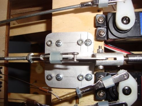
Although the PIX show the guide secured to the servo deck W/screws, do these checks before affixing the guide.
Shove the pushrod rearward until the TW is fully extended to check alignment. The pushrod clevis should still about centered on the guide slot. Some slight variance will be acceptable as long as the width of the clevis will allow alignment.
After you have varified alignment, you may drill the anchor holes in the servo deck W/a pinvise & secure the guide to the deck W/the insertion tongue on the guide base facing forward..
Note in the following PIX that the shoe does extend slightly from either end of the guide. As long as this doesn't amount to over about 25% of the shoe, it is acceptable. The guide is the heaviest component so the length should be minimized.
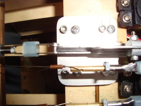
Retracted: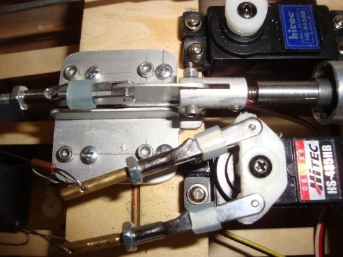
Extended: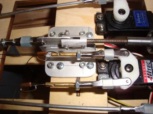
The TW steering wires are very close to the actuator clevis. I felt that proper alignment was paramount so that is how the components were installed.
While there is ample clearance when the TW is extended, the flopping of the steering wires/fittings when retraced does concern me. I am going to subsitute a buttonhead 2-56 screw for the clevice & fabricate some shields to restrain the flopping steering wires/fittings when the TW is retracted, especially @ the center where the wires/fittings tend to get crossed up.
As installed, there is nearly 3/16" of jackscrew threads (6 threads) left in the barrel when extended. That is ample IMO, but I would be leery of much less.
This post will deal W/installing the guide/shoe so that the whole system will be operating in a straight line W/O binding.
1st you should determine the maximum retract position. Remember, the TW on the Fw 190 A doesn't retract fully. When you have established the proper location for the retracted TW, place the shoe/guide into the fuselage W/the jackscrew fully retracted. You will want the clevis of the jackscrew secured to the shoe W/the 2-56 screw supplied W/the actuator. The 5/64" hole you drilled will allow you to screw the 2-56 screw through the slightly undersized hole. It is easiest to do this by screwing out the jackscrew & screwing it back in by spinning the barrel of the actuator after the shoe is inserted into the guide.
W/the shoe on the jackscrew that is fully retracted into the actuator, you can then cut the length of the pushrod as outlined in the TF instructions.
Here is what it should look like. (retracted)
Although the PIX show the guide secured to the servo deck W/screws, do these checks before affixing the guide.
Shove the pushrod rearward until the TW is fully extended to check alignment. The pushrod clevis should still about centered on the guide slot. Some slight variance will be acceptable as long as the width of the clevis will allow alignment.
After you have varified alignment, you may drill the anchor holes in the servo deck W/a pinvise & secure the guide to the deck W/the insertion tongue on the guide base facing forward..
Note in the following PIX that the shoe does extend slightly from either end of the guide. As long as this doesn't amount to over about 25% of the shoe, it is acceptable. The guide is the heaviest component so the length should be minimized.
Retracted:
Extended:
The TW steering wires are very close to the actuator clevis. I felt that proper alignment was paramount so that is how the components were installed.
While there is ample clearance when the TW is extended, the flopping of the steering wires/fittings when retraced does concern me. I am going to subsitute a buttonhead 2-56 screw for the clevice & fabricate some shields to restrain the flopping steering wires/fittings when the TW is retracted, especially @ the center where the wires/fittings tend to get crossed up.
As installed, there is nearly 3/16" of jackscrew threads (6 threads) left in the barrel when extended. That is ample IMO, but I would be leery of much less.
03-12-2013, 02:19 PM
#1258
Well, after all the changes to mine, it's finally completely built and electronics installed, less the batteries, which are in route from Tower. The weather is supposed to be beautiful this weekend so I'll get the paint on it then. Determining the absolute scheme has been a real issue since I like so many but I know the primary colors; other than the base will be RLM 81 and 83.
 03-13-2013, 07:05 PM
#1262
Simple installation of my gear. Patiently awaiting that Tower delivery and my decals from Iflytailies, which should be here by the end of the week. I'm a little concerned about the stock placement of the throttle and choke servos. When mine move (throttle), the former they're on shifts a little. I'm looking at either moving them or adding some support to the area.
 03-14-2013, 05:59 AM
#1266

My Feedback: (10)

Join Date: Sep 2004
Location: Displaced Canadian in Central Texas TX
Posts: 2,601
Likes: 0
Received 0 Likes
on
0 Posts
Clarify something for me; what is the advantage of using the Robart Electric Actuator/Jack Screw versus a Servo with the Mechanical Tail Wheel, weather you got the Actuator separate or purchased as one unit and mounting the Actuator in the Servo Tray Area? I suspect you can limit the travel easier with the Actuator compared to using a Servo!
03-14-2013, 06:07 AM
#1267

ORIGINAL: Ramstein44
Simple installation of my gear. Patiently awaiting that Tower delivery and my decals from Iflytailies, which should be here by the end of the week. I'm a little concerned about the stock placement of the throttle and choke servos. When mine move (throttle), the former they're on shifts a little. I'm looking at either moving them or adding some support to the area.
Simple installation of my gear. Patiently awaiting that Tower delivery and my decals from Iflytailies, which should be here by the end of the week. I'm a little concerned about the stock placement of the throttle and choke servos. When mine move (throttle), the former they're on shifts a little. I'm looking at either moving them or adding some support to the area.
Can't wait to see it in colors. On the decals you picked up, let me know how their sizing is. I purchased their 109 decals, and about half of them were over 50% too big. Too bad as they were nice.
Casey
03-14-2013, 06:33 AM
#1268
Senior Member
ORIGINAL: dasintex
Clarify something for me; what is the advantage of using the Robart Electric Actuator/Jack Screw versus a Servo with the Mechanical Tail Wheel, weather you got the Actuator separate or purchased as one unit and mounting the Actuator in the Servo Tray Area? I suspect you can limit the travel easier with the Actuator compared to using a Servo!
Clarify something for me; what is the advantage of using the Robart Electric Actuator/Jack Screw versus a Servo with the Mechanical Tail Wheel, weather you got the Actuator separate or purchased as one unit and mounting the Actuator in the Servo Tray Area? I suspect you can limit the travel easier with the Actuator compared to using a Servo!
It also cuts off the juice when the retract hits the travel limit. I set up the desired scale retracted TW position (axle just exposed) @ the fully retracted jackscrew position. The jackscrew bottoming out takes care of tripping the control board to cut off current.
The fully extended position of the TW trips the control board in the other direction. I have about .175" of jackscrew left in the barrel @ the fully extended position, about 6-7 threads.
If you have a fancy radio that allows you to control servo speed, there's not much advantage to the actuator. If you don't have that luxury, the control board activated actuator is a much better option IMO.
03-14-2013, 06:39 AM
#1269
ORIGINAL: glazier808
Ram,
Can't wait to see it in colors. On the decals you picked up, let me know how their sizing is. I purchased their 109 decals, and about half of them were over 50% too big. Too bad as they were nice.
Casey
ORIGINAL: Ramstein44
Simple installation of my gear. Patiently awaiting that Tower delivery and my decals from Iflytailies, which should be here by the end of the week. I'm a little concerned about the stock placement of the throttle and choke servos. When mine move (throttle), the former they're on shifts a little. I'm looking at either moving them or adding some support to the area.
Simple installation of my gear. Patiently awaiting that Tower delivery and my decals from Iflytailies, which should be here by the end of the week. I'm a little concerned about the stock placement of the throttle and choke servos. When mine move (throttle), the former they're on shifts a little. I'm looking at either moving them or adding some support to the area.
Can't wait to see it in colors. On the decals you picked up, let me know how their sizing is. I purchased their 109 decals, and about half of them were over 50% too big. Too bad as they were nice.
Casey
03-14-2013, 07:38 AM
#1270
My Feedback: (10)
Join Date: Sep 2004
Location: Displaced Canadian in Central Texas TX
Posts: 2,601
Likes: 0
Received 0 Likes
on
0 Posts
ORIGINAL: SrTelemaster150
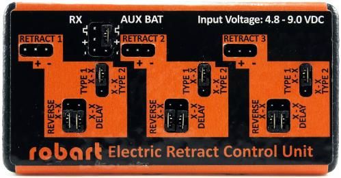
The control board that comes W/the electric maingear controls speed (via aux battery input voltage) & sequencing. (via the delay feature on the board)
It also cuts off the juice when the retract hits the travel limit. I set up the desired scale retracted TW position (axle just exposed) @ the fully retracted jackscrew position. The jackscrew bottoming out takes care of tripping the control board to cut off current.
The fully extended position of the TW trips the control board in the other direction. I have about .175'' of jackscrew left in the barrel @ the fully extended position, about 6-7 threads.
If you have a fancy radio that allows you to control servo speed, there's not much advantage to the actuator. If you don't have that luxury, the control board activated actuator is a much better option IMO.
ORIGINAL: dasintex
Clarify something for me; what is the advantage of using the Robart Electric Actuator/Jack Screw versus a Servo with the Mechanical Tail Wheel, weather you got the Actuator separate or purchased as one unit and mounting the Actuator in the Servo Tray Area? I suspect you can limit the travel easier with the Actuator compared to using a Servo!
Clarify something for me; what is the advantage of using the Robart Electric Actuator/Jack Screw versus a Servo with the Mechanical Tail Wheel, weather you got the Actuator separate or purchased as one unit and mounting the Actuator in the Servo Tray Area? I suspect you can limit the travel easier with the Actuator compared to using a Servo!
It also cuts off the juice when the retract hits the travel limit. I set up the desired scale retracted TW position (axle just exposed) @ the fully retracted jackscrew position. The jackscrew bottoming out takes care of tripping the control board to cut off current.
The fully extended position of the TW trips the control board in the other direction. I have about .175'' of jackscrew left in the barrel @ the fully extended position, about 6-7 threads.
If you have a fancy radio that allows you to control servo speed, there's not much advantage to the actuator. If you don't have that luxury, the control board activated actuator is a much better option IMO.
03-14-2013, 04:16 PM
#1272
Senior Member
ORIGINAL: dasintex
Thanks for the reply, I havn't got this bird yet, but I have convinced myself to go all Electrical Retracts, when I pull the trigger to make the purchase; your install and the device you created to join the Jack Screw and Retract Push Rod is impressive, I can see your concern with the pull pull wires getting hung up, please post a picture showing how you addressed this possible problem, Thanks again for the reply and your postings.
Thanks for the reply, I havn't got this bird yet, but I have convinced myself to go all Electrical Retracts, when I pull the trigger to make the purchase; your install and the device you created to join the Jack Screw and Retract Push Rod is impressive, I can see your concern with the pull pull wires getting hung up, please post a picture showing how you addressed this possible problem, Thanks again for the reply and your postings.
03-14-2013, 04:45 PM
#1273
Ok, I'll bite.. Wouldn’t it have just been easier to have used better servo arms, allowing you the proper clearance for opporation and spacing the servers in a way to allow this?? Seem like a lot of un-necessary efforts and time spent. JMO[ ] I mean, I bet you're the only person EVER to have the need for a shield in this area?? If not, can you post another reference to this method..
I'm just trying to understand your reasoning for you previous modifications. The jack screw.. well, ok maybe but this one completely comfuses me..think you'll have the lead on these methods.
All I can say is... Interesting!
] I mean, I bet you're the only person EVER to have the need for a shield in this area?? If not, can you post another reference to this method..I'm just trying to understand your reasoning for you previous modifications. The jack screw.. well, ok maybe but this one completely comfuses me..think you'll have the lead on these methods.
All I can say is... Interesting!
03-14-2013, 06:17 PM
#1275
Senior Member
ORIGINAL: Ramstein44
Ok, I'll bite.. Wouldn’t it have just been easier to have used better servo arms, allowing you the proper clearance for opporation and spacing the servers in a way to allow this?? Seem like a lot of un-necessary efforts and time spent. JMO[] I mean, I bet you're the only person EVER to have the need for a shield in this area?? If not, can you post another reference to this method..
I'm just trying to understand your reasoning for you previous modifications. The jack screw.. well, ok maybe but this one completely comfuses me..think you'll have the lead on these methods.
All I can say is... Interesting!
Ok, I'll bite.. Wouldn’t it have just been easier to have used better servo arms, allowing you the proper clearance for opporation and spacing the servers in a way to allow this?? Seem like a lot of un-necessary efforts and time spent. JMO[
] I mean, I bet you're the only person EVER to have the need for a shield in this area?? If not, can you post another reference to this method..I'm just trying to understand your reasoning for you previous modifications. The jack screw.. well, ok maybe but this one completely comfuses me..think you'll have the lead on these methods.
All I can say is... Interesting!
ORIGINAL: n8622t
I think Topflite got it right the first time
I think Topflite got it right the first time
The servo arms for the steering are as TF specified. 3/8" from center. My main concern was not so much the wires hitting the jackscrew, but they would cross up when the TW was retracted. Perhaps that doesn't bother you, but I did not care for it.
Is there some other way to keep the wires from flopping around when they are slack?
The steering servo & jackscrew are pretty much mounted where they are inline W/the cable/TW retract pushrod tubes. I can't see where it would be practical to shift them out of alignment. TF picked the spacing, I didn't.