


FN5 turrets for filming out of. 1:3.7
 06-12-2020, 11:29 AM
#1
I've just completed a pair of model FN5 turrets at 1:3.7 scale for a Wellington Ic, The turrets are built from 3d printed SLS nylon, largely screwed together with M1 or M1.6 machine screws, and virtually no glue. This allowed the builds to be backed out of without damage if I needed to change the sequence. This proved a happy decision, adding detail as well as flexibility in assembly. I found that SLS nylon will readily accept a hand-tapped M1 thread into a 0.8mm drilled pilot hole. There are hundreds, if not more than a thousand such holes in each turret, it was more like building a watch than a turret! The most useful tool in my workshop is a cocktail-stick with a small ball of blutak, perfect for teasing M1 nuts onto threads or starting machine screws into threaded holes.
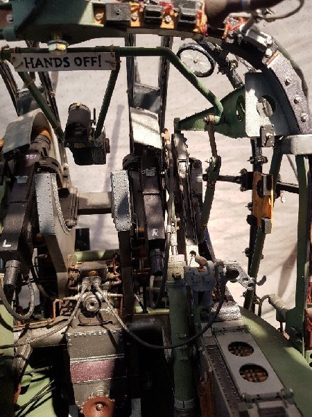
The turrets are designed to be filmed out from, and took 5 years to research, draw and build, although I could now build a pair of turrets in, I think, under 6 months. The hard work was on the CAD side, as I learned Fusion 360 during the course of the project. There were 3 colour schemes in use for such turrets. Early turrets were unpainted, then as manufacture caught up with demand there was a short period where they were painted British Interior Green, wherafter the normal all-black scheme was adopted. I've gone with the green scheme, as the more light inside the turret, the greater the photographic depth of field will exist. As it will be optimal if both turret interior and outside world will be in focus, this will help. The turrets have all working lamps, collimating gunsights, traverse and pneumatically operated elevation, as well as extensive modelling of every switch, circuit breaker, transformer, .303 rounds and hand-dyed period wiring. The rounds in the feed-chutes were individually made and assembled into belts, using a cosmetic link on the viewable side, with a concealed link underneath linking the rounds temporarily until they could be glue into their twisting and curving path within the chutes - which saved having to draw them as a single belt! If anyone would like a similar turret, perhaps in a different scale, weight or level of complexity, I'd be happy to build further ones, although reduction is scale from 1:3.7 may involve changes to build method, mechanical complexity and so forth. Price would be heavily dependant on scale.
One of the difficulties with these was that there are no extant technical drawings, and such plan and side elevation assembly drawings as exist contain numerous errors which had to be corrected. In some cases, these errors were caught late, for example the overly high central console, and the doors. These have been corrected on my master drawings, but remain errors on my built turrets as they were impractical or too expensive, to correct. You may amuse yourselves finding more! One of the hardest aspects was ensuring all moving parts missed each other, whilst also missing the underside of the cupola, which was designed with minimal clearance. Also the front windows are complex-curvatures, and so making these accurately involved considerable efforts to produce a vac-form which looked correct, fitted the internal cupola structure and also allowed moving parts to just miss the underside of the cupola.The next phase is to solve several problems in converting extruded alloy channel into correctly curved geodetic channel (I am utterly hopeless at woodwork!) and produce the internal fittings required to make the joints. So production of the fuselage will likely not commence for a couple of years now.
The latest film of the now completed turrets is linked below this paragraph, but there are many earlier films under the videos tab on my youtube channel. As I was learning to use a video camera, and had no idea about video editing, some of these are a bit repetitive/dull, as it was something I was doing for a few family and friends really. I can recommend the films "moving rams" and "new MK III gunsight" as well as some of the ones covering production of the vac-forming tool.I'm very happy to try and answer questions, or learn of errors. Many thanks to Mark Evans, who provided some component drawings, to Stoney CNC who milled the baseplates, and to Tim Noack who built the gunsight's innards.

A real FN5 on a Wellington
Rear turret model 1:3.7
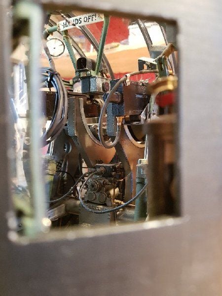
View through hatch
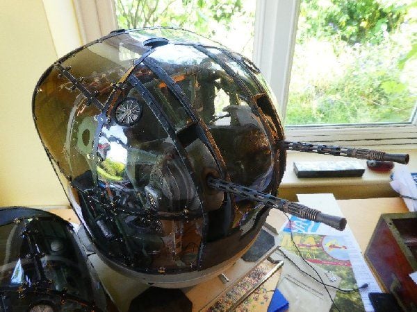
Completed cupolas fitted
Rear turret seat and lap strap
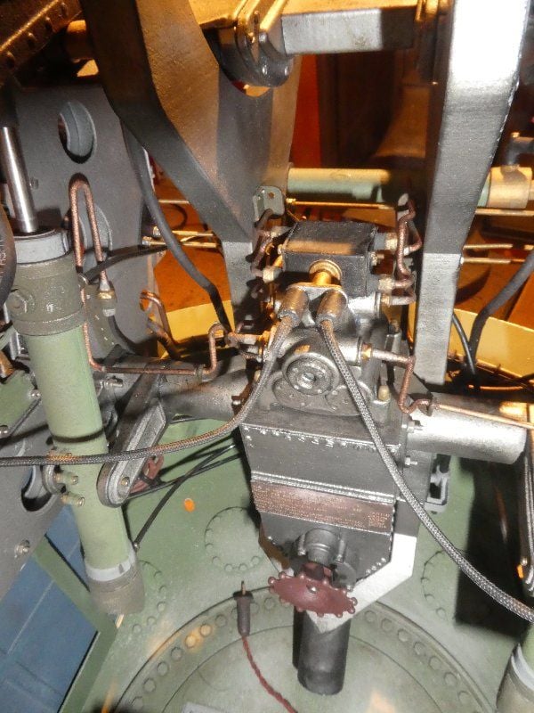
Rear turret view of hydraulic stack and piping
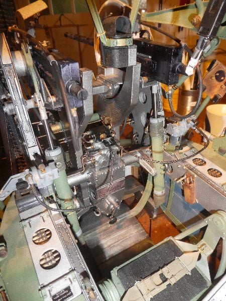
General view of front turret
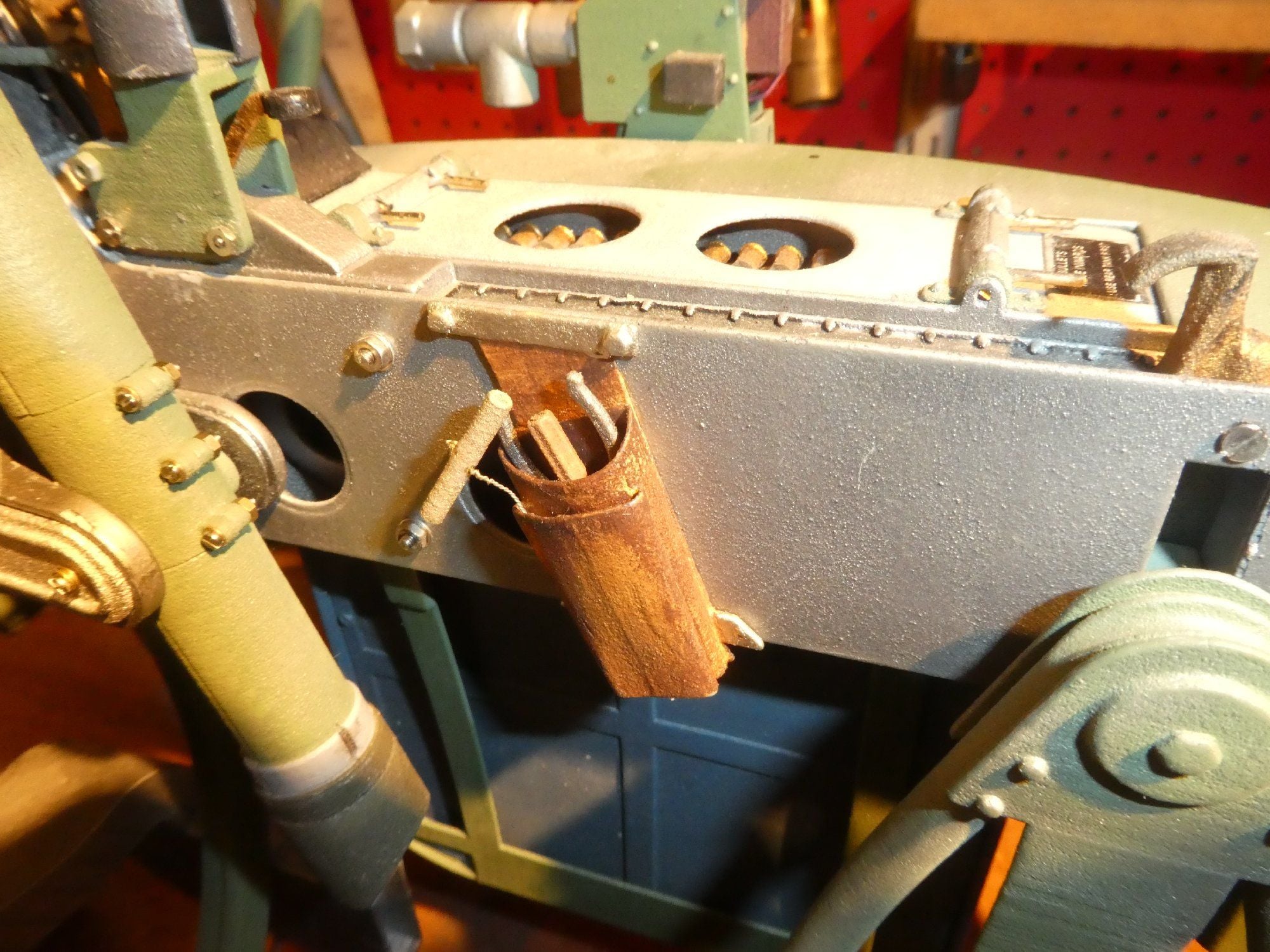
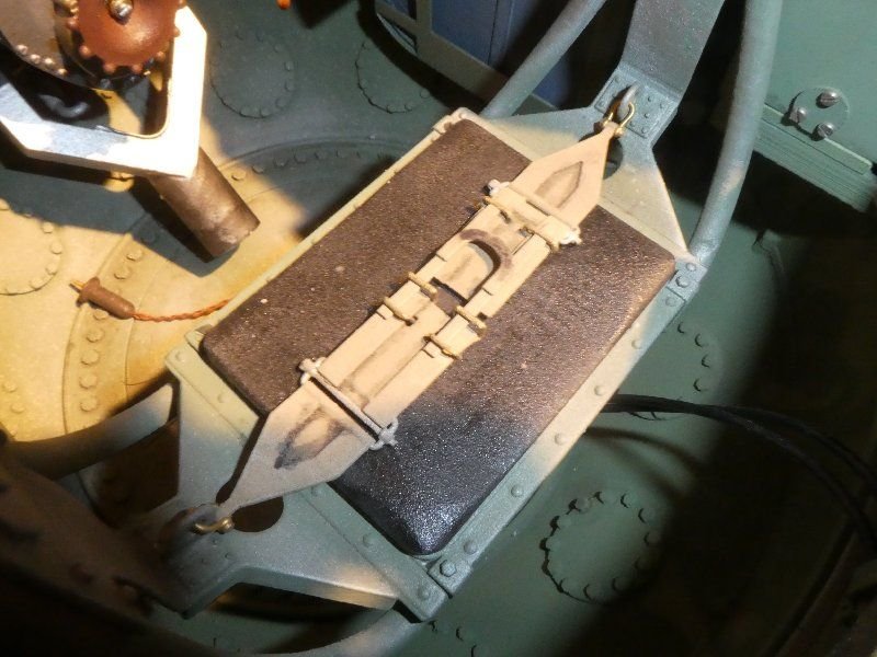
RH tool pouch
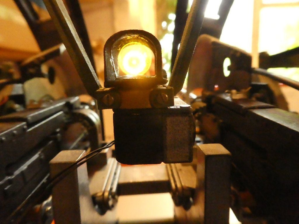
A rather poor photo of the reticule. Dimming was not activated so it is over-bright, and the camera was not focussed on infinity, thereby blurring the reticule
The turrets are designed to be filmed out from, and took 5 years to research, draw and build, although I could now build a pair of turrets in, I think, under 6 months. The hard work was on the CAD side, as I learned Fusion 360 during the course of the project. There were 3 colour schemes in use for such turrets. Early turrets were unpainted, then as manufacture caught up with demand there was a short period where they were painted British Interior Green, wherafter the normal all-black scheme was adopted. I've gone with the green scheme, as the more light inside the turret, the greater the photographic depth of field will exist. As it will be optimal if both turret interior and outside world will be in focus, this will help. The turrets have all working lamps, collimating gunsights, traverse and pneumatically operated elevation, as well as extensive modelling of every switch, circuit breaker, transformer, .303 rounds and hand-dyed period wiring. The rounds in the feed-chutes were individually made and assembled into belts, using a cosmetic link on the viewable side, with a concealed link underneath linking the rounds temporarily until they could be glue into their twisting and curving path within the chutes - which saved having to draw them as a single belt! If anyone would like a similar turret, perhaps in a different scale, weight or level of complexity, I'd be happy to build further ones, although reduction is scale from 1:3.7 may involve changes to build method, mechanical complexity and so forth. Price would be heavily dependant on scale.
One of the difficulties with these was that there are no extant technical drawings, and such plan and side elevation assembly drawings as exist contain numerous errors which had to be corrected. In some cases, these errors were caught late, for example the overly high central console, and the doors. These have been corrected on my master drawings, but remain errors on my built turrets as they were impractical or too expensive, to correct. You may amuse yourselves finding more! One of the hardest aspects was ensuring all moving parts missed each other, whilst also missing the underside of the cupola, which was designed with minimal clearance. Also the front windows are complex-curvatures, and so making these accurately involved considerable efforts to produce a vac-form which looked correct, fitted the internal cupola structure and also allowed moving parts to just miss the underside of the cupola.The next phase is to solve several problems in converting extruded alloy channel into correctly curved geodetic channel (I am utterly hopeless at woodwork!) and produce the internal fittings required to make the joints. So production of the fuselage will likely not commence for a couple of years now.
The latest film of the now completed turrets is linked below this paragraph, but there are many earlier films under the videos tab on my youtube channel. As I was learning to use a video camera, and had no idea about video editing, some of these are a bit repetitive/dull, as it was something I was doing for a few family and friends really. I can recommend the films "moving rams" and "new MK III gunsight" as well as some of the ones covering production of the vac-forming tool.I'm very happy to try and answer questions, or learn of errors. Many thanks to Mark Evans, who provided some component drawings, to Stoney CNC who milled the baseplates, and to Tim Noack who built the gunsight's innards.
A real FN5 on a Wellington
Rear turret model 1:3.7
View through hatch
Completed cupolas fitted
Rear turret seat and lap strap
Rear turret view of hydraulic stack and piping
General view of front turret
RH tool pouch
A rather poor photo of the reticule. Dimming was not activated so it is over-bright, and the camera was not focussed on infinity, thereby blurring the reticule

The following users liked this post:
Ram-bro (08-02-2020)
06-16-2020, 04:15 AM
#2
Ooops, forgot to put the link in for the film of the completed turrets! Best viewed full-size, my channel can be found by searching youtube for Fidd88. Films worth watching are the "moving rams" and "New MkIII gunsight".
The following users liked this post:
Ram-bro (08-02-2020)
07-29-2020, 03:49 AM
#3
So for the past couple of weeks I've been getting my beans in a row to modify the jig I'd built 6 years ago now. When it was built I'd envisaged 1:4.5 scale, but for various reasons, concerning the engines, this had to be changed to 1:3.7. This means that the Wellington's fuselage, as far as the terminal rings at each end (ie not including the turrets) will be 4.7m long, and about 5.2m long them. To this end I've let in 30cm of steel to the central black "datum bar" and the 4 measurement bars on the jig. These will have a "sled" on top, for measuring longitudinal and lateral distances, and also vertical ones. The meaurement bars all needed to be expanded up and outwards of the current position, so have made some removeable extra ironmongery to achieve that. Pics to follow in due course.
07-29-2020, 12:38 PM
#4

There does come a point where shuffling an admittedly interesting build to a multitude of different forum categories becomes an ego thing. This project has already appeared in at least THREE different sections of RCU.
Last edited by allanflowers; 07-30-2020 at 12:34 PM.
07-29-2020, 01:23 PM
#5
{edit}
OK, so I've found out how to see my previous posts. There are 2, not 3 forums, I posted in, a single subject in each. One was the RC Warbirds forum, and the other, the 3d printing forum, as most of construction was 3d printed SLS nylon, and some of the construction methods I thought might be of interest to non-warbird builders. It appears that two such subjects in two widely different forums within RCU have inspired you to post thus. I'm not really sure this is my problem as opposed to some oversensitivity on your part on the subject, for reasons which elude me. If you are a Mod, fair enough, I'll abide by the "rules", if you're not, perhaps you should seek guidance as to whether two posts in two very different forums on the subject is excessive - or not. I'm inclined to think it's perfectly reasonable.... unless against house-rules. Is it?
<shrug>
Last edited by Fidd88; 07-29-2020 at 04:46 PM. Reason: added thoughts
07-30-2020, 12:05 PM
#6
You may be confused with your efforts over on RCSB, where you initiated this same subject in at least TWO separate forums of that site including the 3D Printing area.
Here on RCU, I have seen this subject in three areas, Giant Scale, here in RC Warbirds and in Scratch Building.
Between these five (that I know of), I suspect that you have well covered your subject.
As for being a moderator, I never suggested that I was one – merely that, as a fellow traveler on this website, I was already seeing a plethora of possibilities for people to enjoy and appreciate your project – possibly even a bit of overkill.
I don’t want you to get your knickers in a knot, just maybe get a glimpse in a mirror as to how you might be coming off.
Last edited by allanflowers; 07-30-2020 at 12:08 PM. Reason: spelling
07-31-2020, 01:05 AM
#7
RCSB is a completely different set of forums to RCU, No? So not content with offering an offensive opinion, rather than a pm, as to my 'temerity' in posting to 3, more or less 1 off posts here in relevant forums (out of many dozens) (at 1:3.7 scale, a Warbird and "scratch built/3d printed it qualifies in all 3), you now propose to police what is posted where here, but also on the rest of the internet??
Unbelievable.
Unbelievable.
07-31-2020, 09:21 AM
#8
... the rest of the internet?? That's a GREAT idea. You can put this up on Facebook, Instagram, Twitter, maybe TIKTOK?
Last edited by allanflowers; 07-31-2020 at 09:30 AM. Reason: content
07-31-2020, 01:31 PM
#9
LOL. I can barely use what you lot call a "cell-phone" and "social media" is quite beyond me. I've a little you-tube channel since "mastering" taking videos, but am much more at home with an old manual 35mm. When I got 20 views on a film, I informed my teenage daughter, with apparent earnestness that "her Father's gone viral!" - the received look from her of mixed disbelief, utter horror at a calamity beyond her wildest imaginings - was hilarious. I suspect my going on social-media would elicit a similar reaction!
As for the rest of it - life's too short. I still don't consider my behaviour posting here in 3 different - but relevant - forums here to be even slightly "iffy". If advised by a mod, naturally in future I will conform, but because you saw the same thread somewhere else on the internet? Good grief man, get a life. Or a sense of proportion. Or, (as you lot might say): "Chill!"
As for the rest of it - life's too short. I still don't consider my behaviour posting here in 3 different - but relevant - forums here to be even slightly "iffy". If advised by a mod, naturally in future I will conform, but because you saw the same thread somewhere else on the internet? Good grief man, get a life. Or a sense of proportion. Or, (as you lot might say): "Chill!"
08-03-2020, 12:43 AM
#10

For me this is simply truly outstanding work - we need a lot more of this quality and people with this level of skill should be encouraged to post. Posting on different forums seems entirely appropriate to me since they cater for different interests.
Great stuff Fidd88 - let's see morre of your work please!
Bob
Great stuff Fidd88 - let's see morre of your work please!
Bob
08-04-2020, 07:30 AM
#11
Thanks. But I wouldn't characterise it as 'skilled' per se. Before CAD and 3d printing, it would have been quite beyond me, both of which I learned during the early stages of the project. But I think it shews what sort of thing is possible using this new technology, time and some bloody-mindeness.
I think the more interesting aspect was discovering early on that SLS Nylon-printed parts could readily be drilled to then accept a hand-tapped thread, and that when parts were screwed together with M1 machine-screws, a really solid and strong joint resulted. This completely transformed the whole design and build, as it meant I could print large assemblies as many smaller parts, which saved a fortune in printing costs (costs usually vary with the cube of the volume) but it also allowed for what was a pretty complicated assembly sequence to be back-tracked without having to break glued joints. As I had to backtrack on at least 4 occasions this proved a happy decision. If you look between where the bullets enter the axle, including fixings, 3d printed parts, electrical switches, cams and what-not there's something like 60 parts just on the line of the axle between those two points!
The other wrinkle that came out of this was using splined brass inserts, with internal M1 or M1.6 threads. Not easy to source, but Alibaba has many. These could be inserted via force, or with heat, to provide a decent thread where hand-tapping was tricky. (They're usually pressed into the plastic of electronic devices to allow for (say) the back of a phone to be screwed to the body).
These two techniques proved immensely useful, and the use of real machine-screws added a lot of detail. I doubt that many will want to do this sort of turret, but the build techniques with SLS Nylon/tapped threads are something others may find useful in the years ahead, especially for cockpit detail and the like. Please note that 3d printed ABS plastic simply will NOT take a hand-tapped thread, - it turns to powder - the only way to create one is via the previously mentioned brass splined inserts.
Essential tools:
Drill Press with miniature chucks for drills down to 0.75mm
Pin vices, set of
Nut-spinners
Bluetak - on end of cocktail sticks for teasing nuts onto threads. An unparalled exercise for self-control!
Taps for desired threads, usually used in pin-vice. If working in M1, you'll need lots of them, as periodically they fatigue and snap. Practice helps minimise this. The danger moment is when you reverse the rotation of the tap to clear the spoil into the flutes of the tap, if any lateral force is applied it'll readily snap, so great care is required at that point.
Needle nose pliers, side cutters etc.
Patience!
A really good set of jeweller's screw-drivers, flat-headed.
If you wear glasses, I found a pair made to bring objects 12" distant into sharp focus useful. Magnified viewing is less useful, as it distorts where your tool is in relation to the tiny screws.
IIRC correctly, I made a couple of films on my YT channel which demonstrate all this, and a few other wheezes I hit upon for soldering parts. Very hard to film, but hopefully of some use.
If I was doing it again, I'd have given more thought to the build sequence, prior to construction, as there were several occasions where it was very difficult to get the right tool on the fixing. I'd also have designed the tool for vac-forming the compound curved window panels, and then drawn the metal structure of the cupola to conform to the tool, rather than trying to match the tool to the "metalwork" which proved very, very tricky. Other than that, it was reasonably straight-forwards, if time-consuming.
The link to the film I tried to make covering all of this stuff is at which may be of interest to some:
Last edited by Fidd88; 08-05-2020 at 02:51 AM. Reason: addition of link+typo
