


YA P-38 Build

 09-13-2014, 03:26 PM
#127


Join Date: Mar 2002
Location: Smithfield,, VA
Posts: 1,013
Likes: 0
Received 0 Likes
on
0 Posts
Chris,
You obviously need no help in getting a good finish. I just wanted to give you my ideas on a metalic finish for an aluminum skinned model. I have been using KlasKote ever since the K & B Poxy went the way of the tree huggers. My P-47 was done using a satin catalist with the aluminum paint. I use the 1/64 graphic tape in the primer prior to the final sanding of the primer, as is standard practice. When the tape is removed, the color coats show the panel lines very well. for the panel effects you mention, I buff them with 0000 Steel Wool in different directions. For a more pronounced effect, you could even go to a 000 SW for a few panels. Any clear added over this process eliminates the effect you achieved.
My thinking is that this should be a very subtle effect, as you usually don't notice the panels in a full scale plane until you get to within the "ten foot" range (relative to the model). I'm looking forward to seeing your finished model.
Joe
09-13-2014, 05:11 PM
#128

Thanks Joe,
Im going to do a couple of tests and see what this paint does. The M125 has a lot of metal content in it so Im looking forward to the finished look. One of the things Im interested in seeing is how the steel wool effect works with this clear. I want to do it on the aluminum and on the clear. I had an idea to dirty up the aluminum after steel wool but before the clear to get it in the scratches. We'll see, its trial and error but a few tests will give me some ideas.
Im going to do a couple of tests and see what this paint does. The M125 has a lot of metal content in it so Im looking forward to the finished look. One of the things Im interested in seeing is how the steel wool effect works with this clear. I want to do it on the aluminum and on the clear. I had an idea to dirty up the aluminum after steel wool but before the clear to get it in the scratches. We'll see, its trial and error but a few tests will give me some ideas.
09-15-2014, 01:24 PM
#129

My Feedback: (24)
Received the radiator material from Iflytailies, and set in the hole for sizing. It's just sitting in place about 3/4" back from front of opening, so need it needs the inlet sides, but think the material looks pretty good, price is right, and shipping was fast! Now how to work the inlet to the right shape
Thanks for the tip


Thanks for the tip
Last edited by 70 ragtop; 09-15-2014 at 01:27 PM.
09-15-2014, 10:11 PM
#130
Looks pretty good actually. Maybe the ducting can be done by forming thin balsa sheet or very thin ply sheet to the inside contour of the inlet. Be nice to get the inside small radii. At least the exit side can be pretty straight because the flap makes it variable in geometry. I want the cut the flaps and set them in the open position. Adds more texture to the overall look of the plane, something technical to look at.
09-28-2014, 04:00 PM
#132
Member
Join Date: Feb 2014
Posts: 39
Likes: 0
Received 0 Likes
on
0 Posts
Impressive work Chris and congrats on the successful maiden.
I was thinking of a possible solution if you continue to have issues with the engines overheating while not wanting to cut holes in the cowl. Perhaps drill a hole in the firewall opening the engine compartment to the boom. Then make the radiators you are working on functional by opening the boom to atmosphere, allowing hot air from the engine bay to be sucked out. If worried about fuel getting into the boom use some ducting. Just throwing an idea out there...
I was thinking of a possible solution if you continue to have issues with the engines overheating while not wanting to cut holes in the cowl. Perhaps drill a hole in the firewall opening the engine compartment to the boom. Then make the radiators you are working on functional by opening the boom to atmosphere, allowing hot air from the engine bay to be sucked out. If worried about fuel getting into the boom use some ducting. Just throwing an idea out there...
09-30-2014, 12:16 AM
#133
Thanks!
There is a large hole in the firewall due to the velocity stack which is a couple inches long. It allows the engine to pull cool air from the next compartment. Since its aluminum its also a heatsink for the carb. The compartment behind the firewall is where the fuel tank is but its open to the rest of the interior so theres plenty of fresh air. Ive also opened up the small inlets on the cowls which will drive cool air to the bottom end of the engine and help push the hot air down and out of the 3 exhausts. When their running you can put your hand behind these openings and feel the hot air.
The 38 is going to see its first coat of aluminum paint tomorrow so I'll post some progress shots. Its in primer now and Ive been filling and sanding a lot.
Solved the 50cal barrel issue. I borrowed a die cast model of a 50cal and it has the cooling barrel cover. So I'm just going to make a mold of it and cast resin barrels then cut them to length. Perfect! Lol
10-06-2014, 02:25 AM
#135
My Feedback: (43)
CG before doing my maiden:
Looked at my thread and found the following comments on CG.
Checking to see if anyone who has flown a yellow P-38 can verify this CG?
ps: Since I'm leaving tomorrow for Georgia and will be flying her on Wednesday, I listed this post on 3 different threads hoping to get a quick answer by today.
Thanks
post # 145:
Charles at Yellow said the CG is 3/4" forward of the front main spar.
That puts the CG on the front panel line of the two that are close together as the back panel line is over the main spar.
post # 147:
I previously mentioned that the CG was on the front panel line of the two that are close to each other on the top of the wing.
The bottom of the wing has a 3rd panel line and I'm using that as the CG.
10-06-2014, 10:40 PM
#136
Having flown this one once I can say that the CG on the wing spar worked great. The plane is very docile to be honest. I was comfortable right away with this set up.
if you look at the photos I posted with the factory CG when the gear cycles the CG shift is dramatic. With the CG on the spar not only does the plane fly fine there was no real noticable change in CG and as a result I had plenty of elevator authority. The landing speed was pretty slow with flaps up!
If you use the factory CG I bet the landing speed is double what I had.
I suspended the plane from the wing spars to balance it. The tail is horizontal at the edge of the outer stabs, meaning the edge of the outer stab was level in side view. The gear is up when doing this.
09-23-2018, 11:35 AM
#137
After a long pause and only one flight last year I pulled the P-38 back out for its annual, lol.
Late last year I made new tools to create rivets and the P-38 has begun its transformation. Im not quite done yet but here are some photos to illustrate the progress.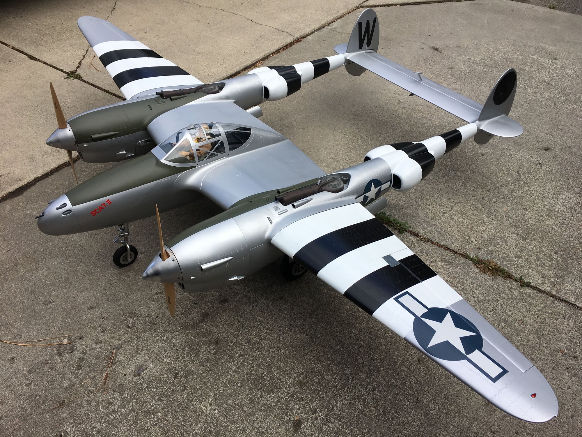
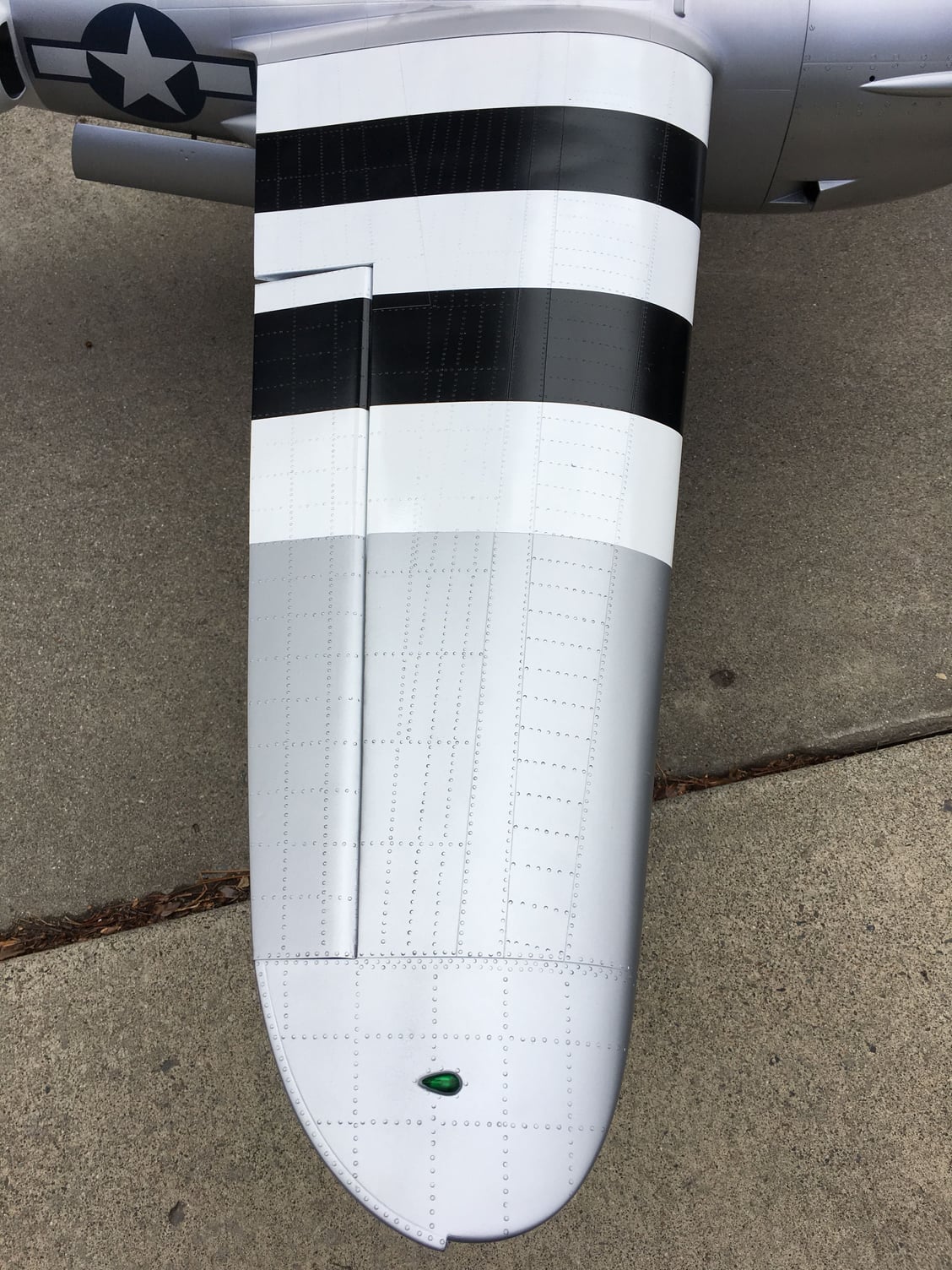
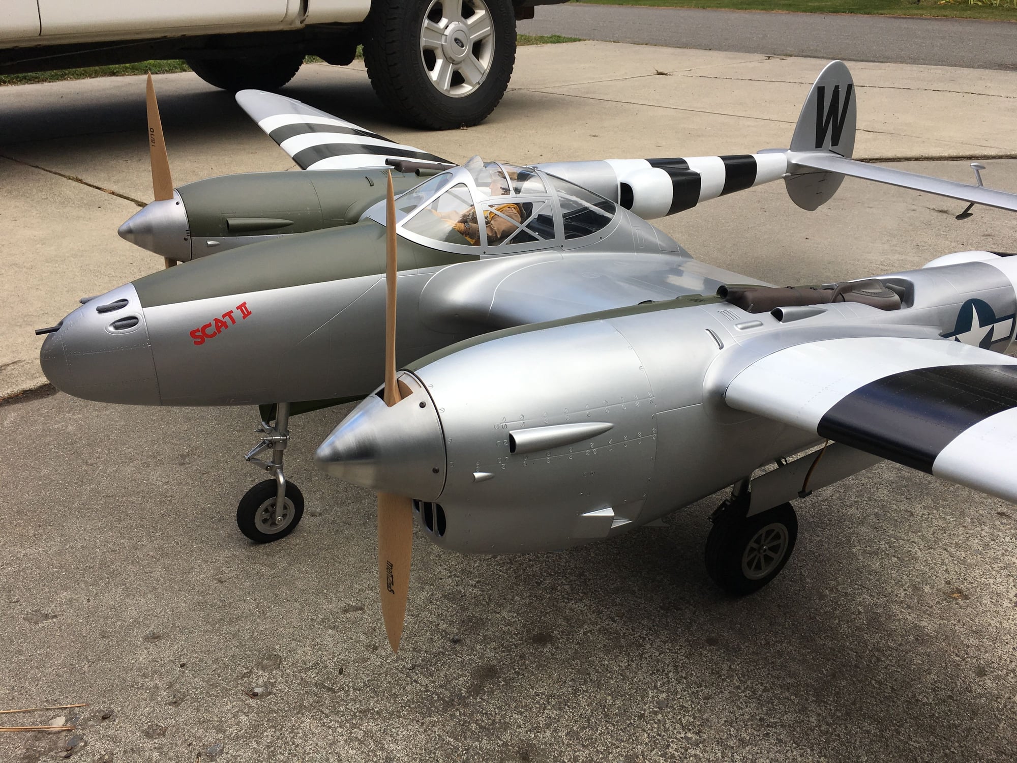
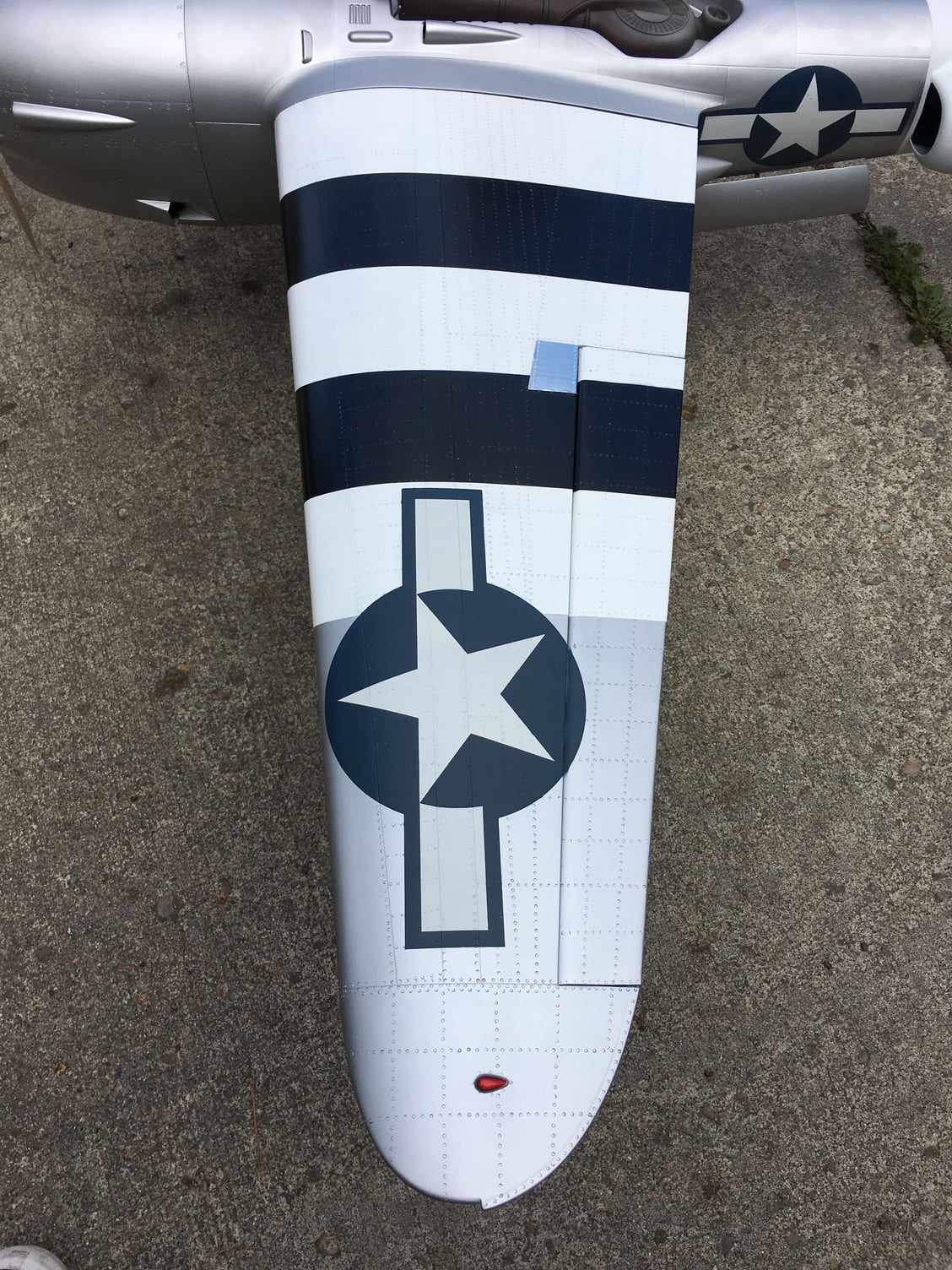
Late last year I made new tools to create rivets and the P-38 has begun its transformation. Im not quite done yet but here are some photos to illustrate the progress.

