


TF 1/5 Scale P-51 ARF Assembly (1ST MISHAP!!!)
 02-07-2018, 07:01 PM
#4001

rossmick,
I bought my first TF P51-D ARF In 2004. I set it up using all of the factory recommended settings. The plane exhibited a left turning tendency on take off and when flying slow and adding power to go around, it dropped its nose. I increased the right thrust to 4 degrees right and reduced the down thrust to 2 degrees down. This resulted in this plane tracking straight ahead and the next 6 TF P51-B and D models used the modified thrust with the same result. The last problem was its frequently destructive ground loop whenever the tail was down on the wheel on both take off and landing (I have a box full of bent gear struts). A friend videoed some of my flights and on one flight in particular, he happened to be holding the camera low as the plane made one of its low speed left ground loops. later I watched the video and noticed that the tail wheel strut wire had flexed over enough to run the tailwhell on its sidewall. I set the plane on the ground and pushed gently on the aft fuselage, the strut wire bent easily to either side. After brainstorming this issue for a while I visited the local hobby shop and found a Sullivan 1/4 scale fixed nose gear strut. I bought 3 of them and drilled out the tailwheel gear strut bearing tube to fit the new strut. The difference in ground handling is 'night and day' with the Sullivan strut, NO MORE GROUND LOOPS, NO BENT STRUTS.
The TF P51 arf AND kit is designed for a glow engine at a 17-19 pound flying weight. I never had one that weighed less than 22 pounds. Even with a beefed and modded wing structure the wing can't stand a drop of 6 inches to the runway on landing without damage. The ONLY landing technique is to roll it on the mains with power and full flaps, NO BOUNCING PERMITTED. Because of the high stress landing requirement with this model I retired my last B model and stopped construction on 2 TF P51 kits. I bought the H9 D model and now enjoy easy landings at slow speeds. The H9 model will not stall and drop a wing on final approach, it lowers its nose and flies a steeper angle until I catch it and add a little power, then continue a controlled slow landing. My TF planes were approached at about 33 mph, and touchdown was at about 27 mph. The H9 model will glide deadstick to the runway with no stall tendency at less than 18-20 mph and can be almost hovered in a 8-10 mph head wind.
I'm not recommending the H9 plane because of factory quality issues, I've had two of them and have switched to the Jerry Bates P51 (plans, wood kit, and optional fiberglass fuselage). Cost is about the same and the JB P51 is an almost Identical design to the H9 P51. Only internal structure is different. The Robart tail retract for the H9 P51 works much better than the gear supplied for the TF P51, it mounts in the rear, but could be installed in the TF plane. There are NO ground loop tendencies with this TW retract.
I am a long time fan of the P51, I enjoy flying them for fun as well as events, but I can't believe I endured flying the TF P51 through so many models. I wish I had known about the Jerry Bates version a long time ago. You should check out the Jerry Bates P51 build thread in this forum.
Jerry Bates P-51B Build "Hell Yes Let's Go!!!"
 02-08-2018, 08:03 AM
#4002
Senior Member

I tried looking for Jerry Bates P-51 and search did not find a forum, could you give me the URL address for it. Decided to order the wing set, so as to continue with the plane. I may decide to pull the DA60 and replace with a DA50. I will definitely move the engine forward 3/16 to 1/4" and see if I can take some of the weight out of the nose. Weight is a real issue now with this wing. I will use your 4 degree right thrust idea. Also will redo the tail wheel linkage and reduce the throw and make sure it tracks straight. I see plenty of bad comments on the H9 51 and the wing connections are sure messed up. I just don't understand the lack of quality control, the wholesalers just must not care. As I understand it, sales of aircraft are going down like a rock and low quality must be a driving force.. Thanks for all the information.
02-08-2018, 08:58 AM
#4004

My Feedback: (10)

Join Date: Apr 2002
Location: Tustin,
CA
Posts: 415
Likes: 0
Received 0 Likes
on
0 Posts
rossmick,
While I am sure there have been issues with wing connections on the H9 Mustang, there are, I am sure plenty that have no problems at all. I myself have one that went together without any issues, assembled in about a week and a half for a warbird event, and now have well over 300 flights on mine! It's the typical deal, with the complaints (even if they are justified) getting all the attention, while the guys that have no issues don't say a word a just go flying. I have had the TF P-51, the AeroWorks, and now the H-9, and it is by far the best flying, handling, and landing of the group.
While I am sure there have been issues with wing connections on the H9 Mustang, there are, I am sure plenty that have no problems at all. I myself have one that went together without any issues, assembled in about a week and a half for a warbird event, and now have well over 300 flights on mine! It's the typical deal, with the complaints (even if they are justified) getting all the attention, while the guys that have no issues don't say a word a just go flying. I have had the TF P-51, the AeroWorks, and now the H-9, and it is by far the best flying, handling, and landing of the group.
02-08-2018, 09:30 PM
#4006

The wingmod is on page 51, post 1263 if anyone is looking. I can't remember what i all did, but I know i did the shear webbing and lots of heavy fiberglass. I hope it holds up.
02-13-2018, 07:28 PM
#4007
Senior Member
All
I have just received the new TF wing set and before I start cutting it open I have some ideas and would like other opinions.
In rereading this thread for the 100th time, I noticed that Ralph White on page 150 cut the ribs to install a continuous ply web front and back of the spars. It got me thinking that with cut ribs you could install a solid wing extender that extended from left outboard rib to right outboard rib.. I think you still need the continuous webs front and rear, but with a solid center the twisting motion would be greatly reduced and absorbed. With this setup I think you would need gussets at each rib web connection front and rear.
Looks to me, from my broken wing, that it twisted back not just broke vertically. This twist, and failure, occurred just past the small wing joiner that comes with the wing set. Understanding with cut ribs now you have a high stress break point right behind the gear. It would be much stronger if the area in front of the gear have a solid 1/4"" spar that ran from left outboard rib to right outboard rib. Tied to the gear mount ribs this would create a strong box to help absorb the rearward twisting vector when the gear hits the ground. Over Kill??
Also, I really don't get how wood screws holding the gear in is a good idea. I do get it that it's better to rip out the gear than snap the wing, but wood screws ??
Where did you get the hot knife?
02-13-2018, 09:54 PM
#4008
rossmick,
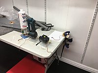
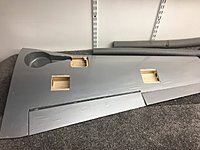
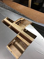
I added an aircraft grade (5 ply, 5/32 or 1/8) plywood reinforcement (full depth in front of the spar, not including the wing sheeting)) going from one rib outside of the outer gear rib across to the rib one bay outside of the opposite outer gear rib. This shear web has a 3/4 inch slot cut in its middle at the rib locations to allow a hard ply rib reinforcement to be added to each gear support rib (4 places) that starts behind the leading edge, goes under the strut cut out and continues back to about 1/2 the distance from the back of the wing spars to the wing trailing edge. I added individual lite ply shear webs behind the spars from the wing center out to the outer aileron servo rib. After this was completed I still felt that the gear ribs needed further support so I added a ply leading edge reinforcement from one bay outside the outer gear ribs across to the same rib in the other panel.
Boxing the gear this way spreads the loads throughout a much larger area of the wing structure, my failures on bad landings after this were limited to the hardwood gear blocks cracking, or pulling away with the aluminum gear frames. A Hobbico hot knife cuts through glue joints easily allowing new or repaired parts to be removed,and reinstalled. All of these mods were done from the bottom leaving the wing top sheeting intact. In these pictures the spar reinforcements have not been done yet. I used a wing under construction to work out the shape of the rib reinforcements that allowed them to be installed in an already completed kit, or ARF wing. The extra black trapezoid shaped piece is necessary to fill the space behind the stock rib, this rib ends at the wing spars and this is partly responsible for the entire leading edge along with the gear support structure breaking away in some cases. The stock design puts two small gear mount boxes on the front of the spars, there is nothing to stop the gear boxes from breaking away on a good landing, this happened to me on one occasion. Adding fiber glass inside the gear bays will not prevent failure, but it does add a ton of weight to the gross.
The leading edge reinforcement I used is air ply soaked with ammonia and scored at the leading edge dogleg breaks to allow it to be bent to follow the leading edge. After the leading edge piece is glued to the back of the leading edge, treat the breaks with Zap. All that is needed to install this after the lower wing sheeting is removed is to cut the front of each rib back for clearance. These mods survived some really bad landings that bent the wood screws holding the gear frames to their mounts, did not break the screws or pull them out of the hardwood gear blocks. Re-glueing the gear blocks back in and replacing the aluminum retract frames is in my mind, an easy fix after a bad landing. No other damage was done to the reinforced wing structure. I DID NOT fill the gear boxes with fiber glass but later I added an additional rib reinforcement to the outside of the gear ribs, minimizing the damage to only cracked glue joints, easily repaired at the field during an event, using thin Zap type glues and zip-kicker. I also remove the stock hardwood gear blocks to replace them with high quality hardwood from Lowes or Home Depot. Look in the Window and door trim section for wood close to what you need. Use premium epoxy (slow set), or Gorilla brand brown glue, clamping the parts in place.
I must emphasize that these mods prevent damage on GOOD landings, if you drop it on the mains from six inches up you can still destroy the wing. Keeping power on with full flaps (I use 55 degrees down for full flaps) and flying it down to the mains EVERY time is the only way to keep your wings intact. If the plane bounces, catch it with a little power and then go around for a better try. To better my landing skills I practised 50 to 75 touch and go landings in all types of weather at each practise session on 2-3 flying days per month. I began to feel I was mastering it when I passed 800 landings. I still devote one flight to touch and go's each time I go flying for practise. I now have over 1600 landings with p51 models behind me.
02-14-2018, 08:58 AM
#4009
Senior Member
sjhanc
Thanks for the great reply.
The engineer in me looks at the problem as a design issue due to the plane be used way past its original specks. As I understand it, the plane is designed for 19 - 22 lbs., but with strong heavy retract gear, good tail wheel (servo in the rear), alum wheels, larger engine and additional weight in the nose to balance, most of us are way past the actual gross design weight. I believe this explains why there has been no improvement in the wing structure over all these years as the designer's feel their calculations are correct for the intended designed gross landing weight. Not saying the wing is correctly built, as even with this last wing set, the spar web was vertical on the front of the spar but horizontal on the rear. I feel the wing twists off more than breaks vertical as the structure is not built for the loads that the additional weight and touch down forces puts on the wing. I have noticed that many are saying their planes were in the 27 - 30 lb. range and that is a 33% increase in gross weight, this structure is just not up to the task. Additionally, the approach speeds have to be faster, so touch down forces have to be higher as you can't float this plane on the ground. Mine broke at the end of the joiner not the gear area. Again, the spar design is just not up the to the task. A little war story, in the F-105 we were told to bring back the 500 lb. bombs if we could not drop on the target. The approach speeds for the thud was 196 kts standard and with an additional 1000 plus lbs. it was close to 210 kts or more depending on conditions. It does not take a rocket scientist to know what came next, higher approach speeds and additional weight farther out on the wing produced cracked spars. So is this TF P-51 correctly designed, no I think not as once you load up all the scale requirements you are way over gross landing weight.
Seems like the Hangar 9 P-51 is better designed for all the additional features, but certainly has issues of its own. So what do I do, more thought and time will tell. I don't think I can leave the wing this weak knowing I am at almost 30 lbs, the wing is just not strong enough to handle the touch downs of the average flyer (me).
Wow, I love to shoot touch and goes, but you sure have me beat on the number, good for you. I just don't have enough time and money to keep buying and rebuilding wings. I really do need to finish the B-25 and this P-51 is consuming all of my time for not that much flying before failure.
Leaning toward enhancing the wing spar structure. If you will notice I used an alum. angle to provide a solid attach point for the gear (no wood screws) and extended it as you have shown here. That concept worked great and the gear area did not fail but the spar at the end of the doubler did. Looks like one area fixed and it exposed the weak spar design for the weight. Decisions, decisions!
Last edited by rossmick; 02-14-2018 at 09:02 AM. Reason: Typo
02-14-2018, 10:46 AM
#4010
rossmick,
I came to the same conclusions several years ago, and looked elsewhere for a better design. I had wished that the H9 plane would be the answer, and 2 of them showed me excellent flight characteristics, but poor quality construction in a couple of critical areas hindered the build and now I've found a fuselage crack at the rear wing trailing edge end of the cockpit that is very similar to the cracks I found in my TF Mustangs after about 100 flights (I lost one to this crack in 2011) I patched and reinforced the structure inside and got 200 more flights, now it is cracked again so I retired it to concentrate on the easier flying H9 Mustang. I lost the first H9 Mustang to a flap servo hardover and considered getting another one, that's when I found the Jerry Bates plane. I am working full tilt on its completion and correcting any design problems as I go.
I will get it to a test flight stage in a few weeks to perfect the engine cooling, when it is flying reliably I'll finish the details and squadron markings. I bought the glass fuse and wood kit, but found that the plane still needs a lot of the wood that is in the all wood kit version. Most of the wood in the glass wood kit is for the wing and tail group, not much is for the glass fuse, but I still need the stuff that is missing. I am tracing the missing parts from the plans and making my own from scratch, using better wood. The wing's airfoil is very similar to the H9 wing, is slightly smaller in area (due to the difference in area of the inboard leading edge of the B model to the D model. The wing is still a much better design than the TF wing, and since I am building it, I can do it my way.
I bought a foam wing kit for the TF mustang and intended to re-cut the bottom airfoil section to change it to a lifting section, just never got around to it. Now I am using the wood for the new JB Mustang wing. I had hopes that a better airfoil for the TF plane would tame its stall characteristics, If I ever get around to fixing the B model that I have, I'll do the airfoil change too. I did modify the stock wing flaps to a slotted flap, that worked better than I thought it would. If I do the foam wing I will transfer the slotted flap design to it, along with a better airfoil and some gross weight loss might make it a much better plane. My best slow speed handling TF P51 had a Fox 2.4 cu in engine and weighed 21 pounds. It was possible to 3 point that plane onto a rough landing strip easily. That one lost its right wing panel to a panel joiner failure at 202 flights. It still had the same structural problem with the gear mounts as all the others did, and its wing came apart on its 11th landing due to no glue in the right panel. Compared to all the other brands, the TF design was the most sucessful behind the larger Ziroli plane, another plans built model with very nice landing characteristics. The Ziroli is a 35-45 pound class model, I am trying to keep my models light enough to benfit my bad back, and now that my Chiropracter has passed away, the gross weight issue is an even more pressing concern.
Last edited by sjhanc; 02-14-2018 at 10:55 AM.
02-14-2018, 11:23 AM
#4011
Senior Member
sjhanc
Good luck in your build. I am building the Ziroli B-25 (for the last two years) and really need to get back to finishing it. Fortunately, I built a jig for the 92" fuselage and it is still in it, straight as a string as I never skinned it for putting items inside. I was thinking about the H9 but think Ziroli is the right answer. Is Hobico the only place to get the hot knife? Be careful of your back. Thanks again for the time to reply.
Good luck in your build. I am building the Ziroli B-25 (for the last two years) and really need to get back to finishing it. Fortunately, I built a jig for the 92" fuselage and it is still in it, straight as a string as I never skinned it for putting items inside. I was thinking about the H9 but think Ziroli is the right answer. Is Hobico the only place to get the hot knife? Be careful of your back. Thanks again for the time to reply.
02-14-2018, 11:48 PM
#4012
The Hobbico hot knife pn #HCAR0770 25w is the only one I have ever seen. It is not perfect because the blade holder constantly loosens as you work. I spend more time tightening the blades than actual cutting. I have worn out 3 of them in the last ten years. When the blade is tight it works fine. I forget the price, its $7-15 or less. When the element is cold it tightens nicely, hot, it won't stay tight. When it works it slices glue lines and a lot of softer materials, wood or plastics. If you get one be careful using it, the damn thing can HURT you. Slices through flesh like butter. It burns nearby materials with the heating element touching or getting too close. For me, it makes some diffiicult jobs easy, it is worth having it. I use it to slice wing skin panels, they are done neatly and can be glued back in.
Last edited by sjhanc; 02-14-2018 at 11:51 PM.
02-15-2018, 11:20 PM
#4013
Senior Member
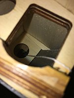
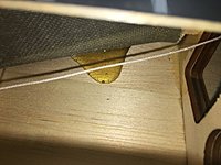
Thought I would take the day to carefully go through the broken wing looking for clues and possible areas that could be enhanced. As you can see, the wing doubler was not the correct size and left a 1/8" plus gap between the top spar and the doubler. This allowed the hardwood spar to split at some point in time, maybe from a previous not perfect landing. I am guessing that it spit first because it was broken later out past the doubler on this last impact. I measured the latest doubler from the new wing set and it is the correct dimension for the distance between the top and bottom spars. Looks to me like this wing was guaranteed to failure with this issue. Problem is, you can't know this situation unless you open the wing and remove the web. Interestingly, the webs on the first 3 ribs are made of ply not balsa.
Still have not decided on cutting a full doubler from gear to gear that goes between the spars, or do webs from the center out past the last gear mount rib. Webs depend on the bond between them and the spar, certainly not as strong as a full doubler, with lightening holes, glued between the spars. Either way the ribs would have to be cut and gusseted in to the spar/web.
Because the inside rib is cut to practically nothing due to the gear struct slot and then the large hole for the air cylinder it is really not much help in absorbing the twist impact to the leading edge on landing. Still working on how to add more support here, maybe my alum angle bolted in through a hole in the spar (seemed to work well). I would really like to see the actual structure of the full size wing to see how they designed this area. I'll see if I can fine a drawing.
02-16-2018, 02:06 AM
#4014
rossmick,
A later wing I modded with the same design ribs as the ones in the above pictures was a built up 3 layer ply-carbon-ply rib that glued to the leading edge reinforcement in front, went under the gear strut (with absolutely minimum strut clearance), then enlarged to cover the hardwood retract mounts and continue to 1/2 the length of the stock rib behind the spars. I had already installed a full depth 5 ply shear web in front of the spars that was slotted between the spars to allow the carbon reinforced rib's blade (not full depth) to pass through. With a carbon rib (4 pieces) on both sides of each hard wood gear mount, I never had any further wood damage in the wing structure. This wing replaced a previously modded wing that suffered an upper spar fracture outboard of the wing mods. The grain in this wing spar did not run parallel to the spar's own length, it was a diagonal grain that covered 2 rib bays from top to bottom of the spar itself. The negative G loading of a hard landing on the wing panel stretched the top spar and the grain split as a result.
I was not aware of the cracked spar and flew several more events with this defective wing. One flying day my pit crew guy and I lifted the plane by the wing tips to check gear retraction with the engine running, that's when the wrinkle in the film covering revealed the spar failure. We were in the middle of our Florida warbird event season so I called my local hobby dealer and had an ARF wing on its way, in a couple of days I had the replacement wing in my hands, got it outfitted with servos and retracts and attended the remaining events with a stock wing. The season ends at the end of March in Florida due to the high temperatures and high humidity, no one wants to try to fly with sweat in their eyes, so, during that summer I modded the new wing as I described above, and other than replaceing bent and cracked retract parts, that wing has endured around 100 flights.
I considered replacing the diagonal grain spars, but instead got a new wing to mod. By the time I had removed all the sheeting and the spars, I would have been doing a lot of work, it made more sense to get a new wing. If there was ANY quality control in the manufacturing process, defective wood could have been thrown out. LOL, we all know that defective wood is NEVER used in the construction of highly stressed wings.
When I received the wood kit for the JB P51B, balsa wing spars were included. I replaced them with hardwood spars that I selected myself for a small extra cost. Since I have made up my mind to never buy another ARF model, I have complete control over the quality of the wood I use.
I am almost finished installing the wood parts in the JB P51's glass fuse, I should be checking the cg in a week or two. After that I can start installing the radio and other stuff.
02-16-2018, 09:17 AM
#4015
Senior Member
I am with you on never buying another ARF - China junk. Too bad we can't build an ARF here in the states with some quality and reasonable cost. The product most likely would have to sell direct as the wholesalers would not buy the it because they would make much more profit buying cheap junk from China.
I bought a Hemple Super Decathlon and had to rebuild the gear area in it as it was so weak the gear twisted out on taxi back. Off my soapbox now.
You used carbon fiber, I used alum angle which also allows for bolts rather than wood screws to hold the gear in. Option A is the one piece extended 1/8" ply webs front and back - would be much easier than option B, but cutting out the existing webs at the center of the wing will be interesting. Option B - I have a large sheet of 7 ply 3/8" so I could try the extended doubler concept to see if it will work. I would need to cut the thicken section away from the supplied doubler and glue it to the longer spar at the center to match the added depth at the center of the wing. This way I could use the existing spars and just go between them, that had to be a real pain cutting them out. Another problem here is cutting out the existing rib section between the spar when the ribs are cut away. Maybe removing the spars and going full height on the doubler/spar would be the way to go. Option A is looking better and better for my 30 lb. beast.
One other sad factor is that the wing haves do not form a perfect joint when put together with the doubler installed, there is at least an 4" long 1/8" gap at the trailing edge. I don't remember this issue with the first set of wings, nothing that can't be fixed, but just another junk build issue. For the $300 cost of this wing set I would have expected certainly more than what I got, didn't this wing set sell for $150 before?
At least when you build your own you know what the parts are made of and how they are installed.
Good luck on your build I am sure it will come out just fine.
Last edited by rossmick; 02-16-2018 at 09:22 AM.
02-16-2018, 01:09 PM
#4016
A while back some one asked about using the ARF wing to replace a damaged kit wing, since I have both types on hand I checked to see what fit what. The two wing types, kit and ARF are interchangeable on either fuse wing saddle. They used different methods for fuse attachment, the ARF has dowels in the leading edge and bolts in the rear, and the kit reverses the dowels and bolts. Either fuse can be modified easily to suit the type of wing used.
I used to be able to find D or B kits online for $249, some times on sale at Tower for $199. That was the old days, I don't know what a kit goes for now. I wanted to build an A model and bought a D model kit framed up for $150 from an estate sale. I removed the D turtle deck to build an A deck on it and then got into the H9 Mustangs. They were so much better flying models that I stopped work on all of the TF Mustangs I own.
I continued to fly my last TF B model until I discovered more fuse cracks, then retired it and am now stripping it for radio gear and retracts. My disappointment with the H9 model's issues turned me back to building Mustangs from plans. I am making steady progress with my new JB Mustang, I expect good flying with it.. If it all works as I hope, I will buy a new JB wood set for the all wood fuse to get all of the parts left out of the fiberglass wood set, which I am currently making, one by one, from the plans I have on hand. I will also buy the glass fuse to use instead of building the wood fuse, I don't think I can make a wood fuse look as good as Vic Catalasan's excellent molding.does.
Incidently, Vic's glass fuse is almost as light as the H9 fuse, The bare TF fuse weighs twice what the H9 and the JB glass fuse weigh out-of -the-box.. Wing weights 'bare' for all of them are within a pound.
JB claims his Mustang can be built in the 25 lb. range, I think it will fly light at up to 35 lbs, comparable to the H9 Mustang at that weight. Both of my H9 Mustangs grossed 27 lbs. 5 oz., they fly VERY light at that weight. I have witnessed the larger Ziroli Mustangs flying light at over 40 lbs. I have a lot of experience with TF Mustangs, they fly light at 23lbs or less, and fly like a brick over 25 lbs. At ANY gross weight the TF Mustang stops flying when the prop stops, they do not glide. The PICA Mustang, equal in size (but not in airfoil) to the H9 and the JB, also does not glide when deadstick. I witnessed a PICA Mustang go deadstick at over 400 feet, then fail to complete a turn back to the field. It stalled at ten feet over smooth grass, then destroyed itself. I had heard of Meister, Ziroli, and several other plans built Mustangs, saw them fly, and voted for the ARFs, a mistake on my part, but I did have a lot of fun with the TF versions over the last 15 years, averaging over 100 flights per year. For a long time I kept track of number of flights and operating expenses, it worked out to $13 per flight., not counting trip expenses.which usually cost $100-200 per day for out of town.
If my memory is correct, I paid $157 per fuse from Tower (2 each) and $175 each for half a dozen ARF wing sets. When I looked to replace the current cracked fuse, the price turned me to the H9 Mustangs.
Back in the 70-80s I bought a lot of smaller glass fuse-foam core sheeted wing basic airframes, failing distance vision forced me to the larger models. After cataract surgery in 2010, I can see as good as when I was a teen, but now I like the larger models.
Well, got to get back to work on the B model,
Steve

 02-16-2018, 03:25 PM
#4018

Thanks Top Flite for not fixing your design flaws on the giant P-51D, you’ve only had 15years!
Shear webs made of balsa and to top it off the grain in the wrong direction. On landing it causes the landing gear to escape through the top of the wing. Poor for a plane of this size/weight.
Fixed now though just a pisser to hack a new model to bits


Shear webs made of balsa and to top it off the grain in the wrong direction. On landing it causes the landing gear to escape through the top of the wing. Poor for a plane of this size/weight.
Fixed now though just a pisser to hack a new model to bits
Last edited by Colin_Mc; 02-17-2018 at 04:04 PM.
02-16-2018, 10:08 PM
#4019
Senior Member
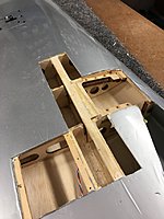
After taking in all the different fixes I have seen, I decided to cut out the lower spar to the outboard gear rib, notch out the ribs and cut a long continuous new solid 3/8" ply spar that sits on the top spar and eliminates the lower spar to the outside landing gear rib. I thought removing the lower spar would be difficult, but it came right out with little effort. I cut ribs with an oscillating saw, again dead easy. Rib sections were so poorly glued to the top spar I just pushed them over with my finger, nothing really to even clean up. I cut out the prototype spar which actually goes past the outboard gear rib but is notched to accept the hardwood spar from the outboard section of the wing. This section will receive a 1/8" ply web to help bind all the connections. The new solid spar weighs in at 11ozs where all the removed parts weighed in at 7 ozs. so I have a plus 4 oz. gain. I will not be putting any lightening holes in the new spar as I do not want to compromise it's strength. I am sure this can be done but without some informed knowledge of where to place them I will just not do any of them. Prototype spar was fashioned from the original doubler for dihedral angle which came in at 5 - 6 degrees. I will spend some more time making sure that the new spar is symmetrical. So far all is going together as planned. Once fitted, the final spar will be glued to top spar, existing webs and the ribs themselves. Rib connections to spar will be done with hardwood gussets. More work to be done on the gear mounting section and I will use a new alum angle designed as I did on my first upgrade but will stop it at the new spar and will not extend through the spar and back to the rest of the rib.
I used the damaged wing as a test bed to cut things out before I starting cutting on the new wing set (as the third photo shows). This concept worked so well I may just rebuild the old damaged wing as a backup (maybe).
I used the damaged wing as a test bed to cut things out before I starting cutting on the new wing set (as the third photo shows). This concept worked so well I may just rebuild the old damaged wing as a backup (maybe).
Last edited by rossmick; 02-16-2018 at 10:20 PM.
02-16-2018, 10:33 PM
#4020

Join Date: Oct 2011
Location: Kelowna BC Canada
Posts: 188
Likes: 0
Received 0 Likes
on
0 Posts
how hard is it to monokote the giant p51? Theres a guy selling a rtc and was just wondering how or what techniques you guys have. If i bought it, i'd make it a red tail. How do you paint the cowl too?
Trevor
Trevor
02-17-2018, 01:32 AM
#4021
I get really good results with Ultracote brushed aluminum. It is shiny but can be buffed to reduce the shine with fine steel wool #0000 and Painted markings stick very well. Most hobby shops don't stock it but Horizon does carry it. If the plane is left in direct sunlight the film will wrinkle, but nowhere near as much as the other brands. The recommended method for application is to lay a piece over the part, then iron it, (220degrees) starting in the middle and pulling the film's edges as you work towards the part's edge. Use a cloth cover over the iron's shoe to avoid scratching the film. For large panels or compound curves an extra set of hands helps. After the film is in place with the wrinkles pulled out, shrink it at 350 degrees with the iron. A blow gun can be used but keep it moving, over heating the film will cause it to melt and large holes appear without warning. The brushed aluminum has a metal grain that can be oriented to simulate panels. I cut smaller panels out of aluminum duct tape and use a small brass tube to indent rivet heads into the tape. Use actual metal a/c duct tape, not the DUCK tape. I get mine from Lowe's and Home Depot, and ACE hardware carries an extremely thin aluminum tape. All of these tapes will have printed manufacturer's markings applied (for building inspectors), use acetone to wipe the markings off. I do my film covering outside in the Florida sunshine, hot and sweaty work, but fewer sun wrinkles later on. If you do individual panels, overlap the film 1/4 inch and avoid heating the panel lines when shrinking the film or removing sun wrinkles.
My planes take on a natural warbird-in-combat-service wear and tear look over time that looks natural. The particular model in the pictures is a collection of crash parts and a new wing from Tower. I used Ultracoat crome on the upper surfaces to imitate the highly polished look of the Collings Foundation's airshow plane. The brushed aluminum is on the fuse sides with tape access panels, the tail group is Utracote silver with transparent red stripes. Since the wing came covered with Monocoat aluminum I left it alone, but most of the sun-caused wrinkles show up on it and have to be ironed out before every event. I like the brighter finish, it reflects the sun's rays better and keeps the retract air line blowouts to a minimum.
My planes take on a natural warbird-in-combat-service wear and tear look over time that looks natural. The particular model in the pictures is a collection of crash parts and a new wing from Tower. I used Ultracoat crome on the upper surfaces to imitate the highly polished look of the Collings Foundation's airshow plane. The brushed aluminum is on the fuse sides with tape access panels, the tail group is Utracote silver with transparent red stripes. Since the wing came covered with Monocoat aluminum I left it alone, but most of the sun-caused wrinkles show up on it and have to be ironed out before every event. I like the brighter finish, it reflects the sun's rays better and keeps the retract air line blowouts to a minimum.
02-17-2018, 06:27 AM
#4022
I covered my plane with film, but didn't use Monokote. I found a film that is better than Monokote in every respect...it goes on easier, shrinks tight and doesn't wrinkle badly over time, is durable and costs about 1/3 the price of Monokote. I used Hobbyking Bright Silver film: https://hobbyking.com/en_us/covering...___store=en_us and Olive Green: https://hobbyking.com/en_us/covering...___store=en_us
The silver film has a brushed looking finish that isn't mirror-like at all. It looks very much like aluminum.
The silver film has a brushed looking finish that isn't mirror-like at all. It looks very much like aluminum.
02-17-2018, 04:00 PM
#4023
02-17-2018, 08:35 PM
#4024
Senior Member
I opened up the other new wing section and removed lower spar and cut out the ribs. Joined the wings and dry fit the spar, had to reverse the wedge as the spars don't run straight across the sections so had to cut wedge pieces to fit at rear of spar to the aft web piece. There is a slight 1/8" bow from the center out to the outboard gear rib as there is no straight line through the two wing sections.
Started work on alum angle gear hold down mount, but this time went with a 2" x 2"-1/8" angle so I can just thread the angle for the gear bolts. I plan on doing a much more accurate install of the angles that I did on the first upgrade for the gear openings and the struct clearance when retracted. I pretty much just hacked the openings in the first angles rather than any accurate measurements as I was in a hurry to get the plane done for an event. I will bolt and epoxy the angles to the ribs and will add an additional jib section to thicken the attach points. Photo shows hold down angle in place, dry fit at the correct height, on the inboard rib with more work to do on bolt down area. It will most likely take all day tomorrow to create the other hold downs.
Started work on alum angle gear hold down mount, but this time went with a 2" x 2"-1/8" angle so I can just thread the angle for the gear bolts. I plan on doing a much more accurate install of the angles that I did on the first upgrade for the gear openings and the struct clearance when retracted. I pretty much just hacked the openings in the first angles rather than any accurate measurements as I was in a hurry to get the plane done for an event. I will bolt and epoxy the angles to the ribs and will add an additional jib section to thicken the attach points. Photo shows hold down angle in place, dry fit at the correct height, on the inboard rib with more work to do on bolt down area. It will most likely take all day tomorrow to create the other hold downs.
Last edited by rossmick; 02-17-2018 at 08:46 PM.
02-17-2018, 11:09 PM
#4025
On painting the engine cowl, the stock cowl has the checker board pattern molded, I don't remember for sure, but I think the ARF cowl is smooth. I replaced my cowls and canopys with better quality parts from Fiber Glass Specialties. They can supply cowlings with smooth or checkerboard surface. TF aerosol paint is good quality paint for RC models, if applied according to the instructions it has the right color match and is gas and glo fuel fuel proof. I have even painted spinners by mounting them on an old crankshaft prop bolt. Chuck it into a 1/2 inch variable speed drill, turn it slowly as you spray thin coats, let it dry between coats and wet sand any orange peel out. Apply a shine coat of clear or flat clear as you need for your theatre markings.
Alternatively, sand the checkerboard pattern off and prime and paint the cowl, but it may be prettiy heavy. It is not a good thing to have a heavy cowl, engine vibrations will wear the mounting holes out pretty quickly. If you need weight for CG it is better to bolt heavy metal to the firewall.
Alternatively, sand the checkerboard pattern off and prime and paint the cowl, but it may be prettiy heavy. It is not a good thing to have a heavy cowl, engine vibrations will wear the mounting holes out pretty quickly. If you need weight for CG it is better to bolt heavy metal to the firewall.