


125% (1/4 scale) Anderson TA-152H
 08-07-2014, 09:41 PM
#26

Thomas,
I just received a few pics from my client in Germany, he is building the 1/5 Ta152 kit and has replaced the down lock scissor from the Sierra gear with air cylinders for a more scale representation
Also the inner door system of closing and opening is 100% scale.
JG
I just received a few pics from my client in Germany, he is building the 1/5 Ta152 kit and has replaced the down lock scissor from the Sierra gear with air cylinders for a more scale representation
Also the inner door system of closing and opening is 100% scale.
JG
Last edited by JGrc; 08-07-2014 at 09:55 PM.
 08-12-2014, 09:34 PM
#27

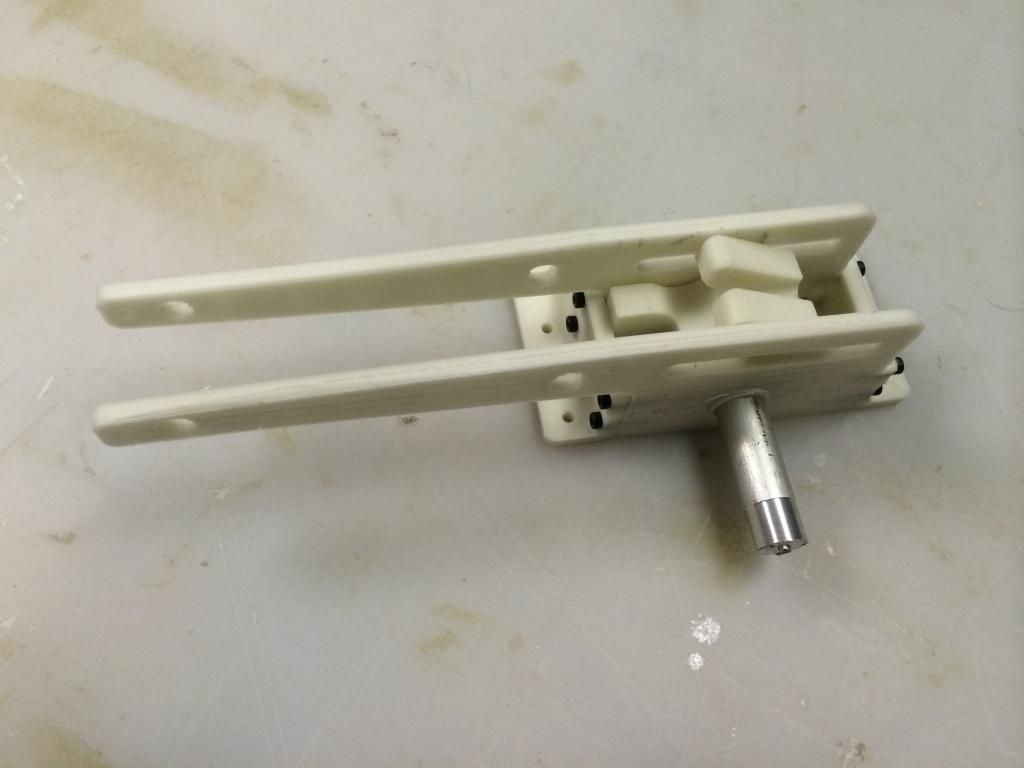
While filler was drying on the. V173's, i fiddled with the 3D printer and started printing the beginnings of the 1/4 scale TA152/FW190 retract mechanism. Here are a few photos:
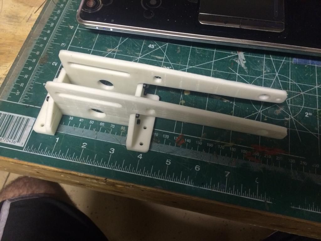
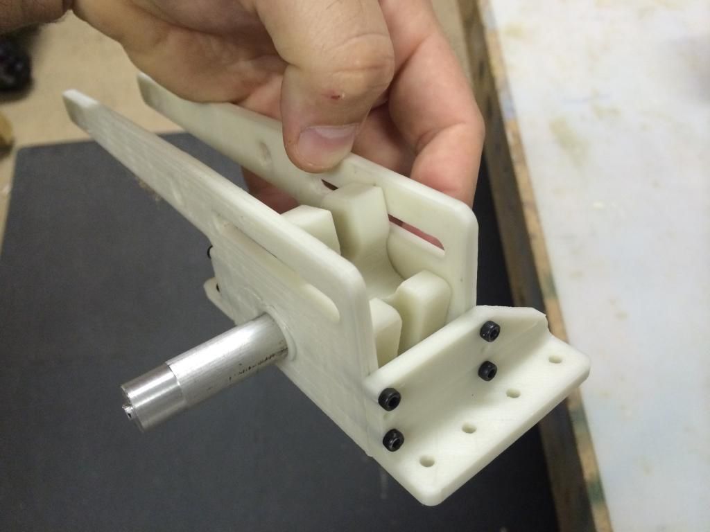
The retract mechanism consists of 3/16" aluminum side plates with a 5/8" hole for an oil-lite bronze bushing for the 1/2" pivot axle. The frames are bolted to a pair of 1/4" thick L brackets with a total twelve 4-40 bolts with an additional Eight 6-32 bolts to mount the entire thing to the gear plate. The trunnion is roughly 1/2" thick steel (possibly titanium, i need to do the stress analysis before i make up my mind),(which has yet to be printed). The slider is 3/8" round brass. The cylinder can be either a 5/8 or 3/4" bore industrial clippard cylinder (or a set of firgelli linear actuators for those wanting electric.
For the Ta152, there are two mounting options without any changes having to be made to the retracts.
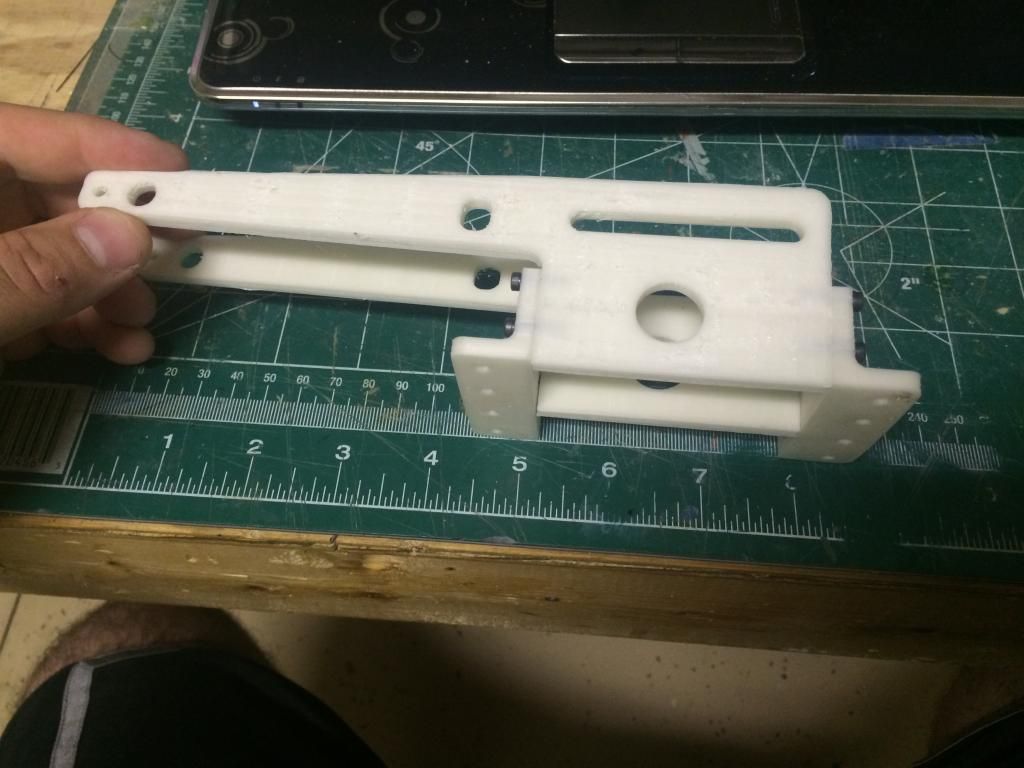
1: Cylinder facing opposite of the strut:
2: cylinder on the same side of the strut (forgive me for having the mechanism upside down, i dont have the second one printed and didnt want to change the assembly in this one to show it in the same top down orientation as option 1):
Personally, i will probably mount my gear as in option #1. This allows very easy maintenance to the cylinder connetions without having to remove the landing gear and gives a nearly 100% open area for a completely scaled out gear well. The material left around the opening in this rib is sufficient to not reduce the strength any and the Merlyn locks can be completely hidden from view inside the wheel well, with a second in the flap well, so no external fasteners will be required for wing attachment!


The retract mechanism consists of 3/16" aluminum side plates with a 5/8" hole for an oil-lite bronze bushing for the 1/2" pivot axle. The frames are bolted to a pair of 1/4" thick L brackets with a total twelve 4-40 bolts with an additional Eight 6-32 bolts to mount the entire thing to the gear plate. The trunnion is roughly 1/2" thick steel (possibly titanium, i need to do the stress analysis before i make up my mind),(which has yet to be printed). The slider is 3/8" round brass. The cylinder can be either a 5/8 or 3/4" bore industrial clippard cylinder (or a set of firgelli linear actuators for those wanting electric.
For the Ta152, there are two mounting options without any changes having to be made to the retracts.
1: Cylinder facing opposite of the strut:

2: cylinder on the same side of the strut (forgive me for having the mechanism upside down, i dont have the second one printed and didnt want to change the assembly in this one to show it in the same top down orientation as option 1):

Personally, i will probably mount my gear as in option #1. This allows very easy maintenance to the cylinder connetions without having to remove the landing gear and gives a nearly 100% open area for a completely scaled out gear well. The material left around the opening in this rib is sufficient to not reduce the strength any and the Merlyn locks can be completely hidden from view inside the wheel well, with a second in the flap well, so no external fasteners will be required for wing attachment!
08-12-2014, 10:04 PM
#28
Thomas, if you going to design the frame and trunnion, don't forget the full size has 8� forward rake built in. That means the hardwood retract mounts have to have the same angle in relation to the main spar. SIerra gear only has 2 degrees, not enough.
Without this pintle, the wheels do not lie flat in the wheel well.
JG
Without this pintle, the wheels do not lie flat in the wheel well.
JG
08-12-2014, 10:51 PM
#29
Thomas, if you going to design the frame and trunnion, don't forget the full size has 8� forward rake built in. That means the hardwood retract mounts have to have the same angle in relation to the main spar. SIerra gear only has 2 degrees, not enough.
Without this pintle, the wheels do not lie flat in the wheel well.
JG
Without this pintle, the wheels do not lie flat in the wheel well.
JG

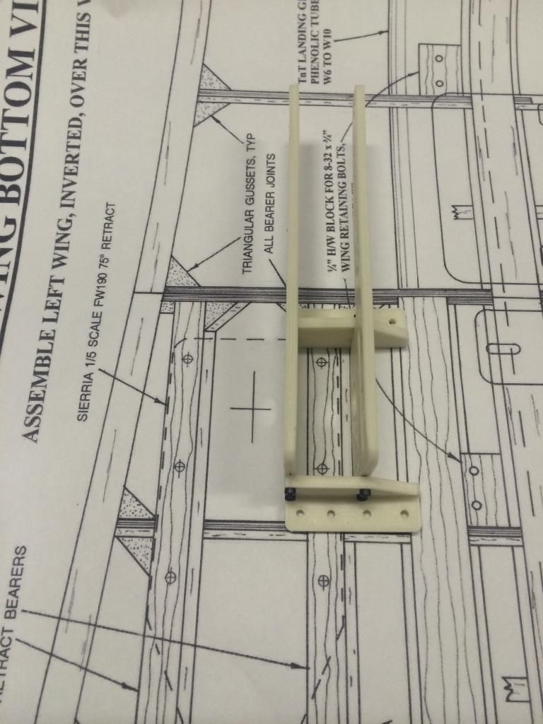
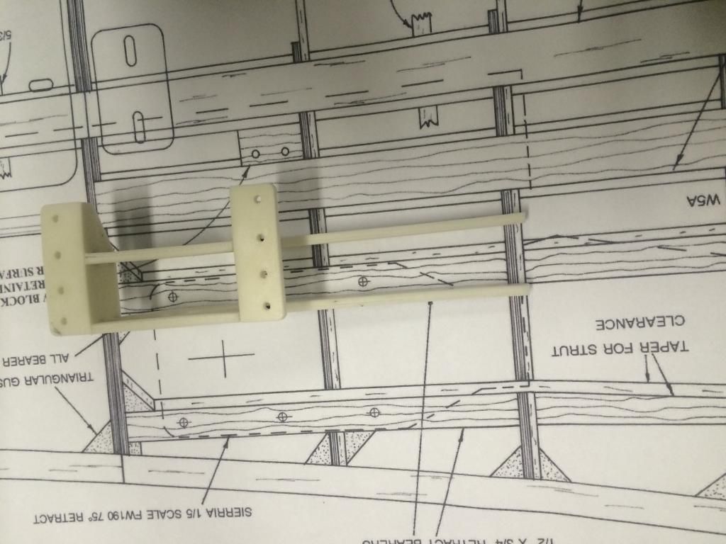
The 1/4" 10-ply aircraft ply retract mount plate is not only glued to two 3/16" thick wing ribs, it also gets glued into a 1/2"x1" spruce spar and the 1.5" wing tube socket there is also a bunch of hardwood tri-stock and some additional aircraft ply structure to tie all of this area into one giant box of impossible broken-ness
08-13-2014, 09:41 AM
#31
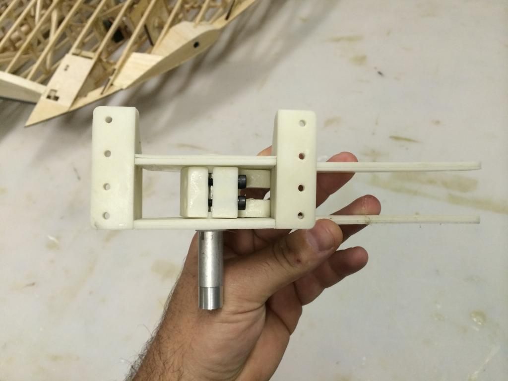
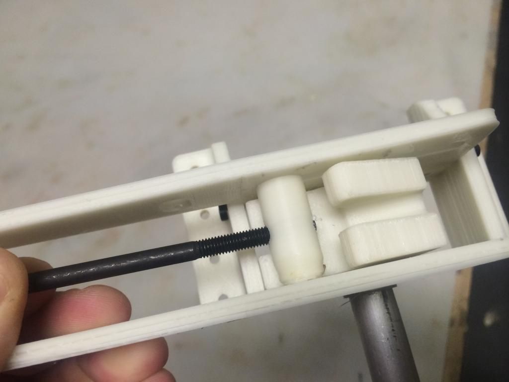
The pivot axle bushings and trunnion were printed last night, the slider is on the printer now.
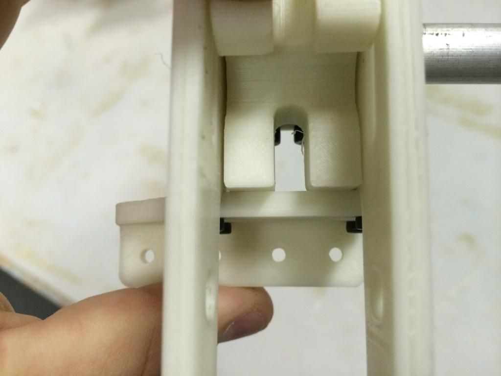
Like i said earlier, the axle is 1/2" diameter steel (im using scrap aluminum in the mockup). The trunnion has a pair of 8-32 bolts that clamp it onto the axle. In retrospect, i will probably have a flat filed onto the axle and leave a flat section of material in the trunnion so the two "key together" and can not rotate. Im not sure if this is 100% necessary, but it seems like a good idea to me
The trunnion is a full 1" thick with two indentations that allow the bronze axle bushings to inset into the trunnion roughly .060". This keeps all chances of sideplay within the assembly to a minimum.
For down locks, we have not only the over centering of the slider bar over the trunnion, the trunnion also hits the retract end bracket under the cylinder mount legs providing a very effective and positive lock. If you break one of these retract units, you have really done something! Typically i like to design in some sort of weak link, but on an airplane of this size and weight, that weak link will need to be the mounting structure as the time involved in the machining of these struts is pretty high.
Heres more photos


 08-13-2014, 10:08 AM
#32
Senior Member

Thomas, I noticed you mentioned titanium for the trunnions, while I believe titanium would be plenty strong enough. What about the cost factor in having them made? Isn't titanium pretty hard to machine? I say the more the better because of strength vs weight bonus, just curious?
Also because of the weight, I know you plan to be around 50 lbs but knowing the amount of scale details put into it Im kind of thinking its going to be more. I wonder if you would be better off using a carbon fiber built type ribs in the wing next to the gear area as well as around the gear just for strength. Or do you think the aircraft ply will withstand a hard landing or two?
Oh and I must say WOW That landing gear is going to be huge!! I want to see the whole thing put together to get a visual! That 3d printer is awesome, I may have to get one after all!
08-13-2014, 10:23 AM
#33
Thomas, I noticed you mentioned titanium for the trunnions, while I believe titanium would be plenty strong enough. What about the cost factor in having them made? Isn't titanium pretty hard to machine? I say the more the better because of strength vs weight bonus, just curious?
Also because of the weight, I know you plan to be around 50 lbs but knowing the amount of scale details put into it Im kind of thinking its going to be more. I wonder if you would be better off using a carbon fiber built type ribs in the wing next to the gear area as well as around the gear just for strength. Or do you think the aircraft ply will withstand a hard landing or two?
Oh and I must say WOW That landing gear is going to be huge!! I want to see the whole thing put together to get a visual! That 3d printer is awesome, I may have to get one after all!
Also because of the weight, I know you plan to be around 50 lbs but knowing the amount of scale details put into it Im kind of thinking its going to be more. I wonder if you would be better off using a carbon fiber built type ribs in the wing next to the gear area as well as around the gear just for strength. Or do you think the aircraft ply will withstand a hard landing or two?
Oh and I must say WOW That landing gear is going to be huge!! I want to see the whole thing put together to get a visual! That 3d printer is awesome, I may have to get one after all!
The Aircraft ply i use is really strong.. The 1/4" isnt like the acft ply you get from the LHS with 6plies, this stuff has 10plies and is like steel. Plus it will probably get a layer of carbon fiber on either side of it. Same goes with the ribs the plates are mounted to, except they will probably get a G10 doubler epoxied to them so as to also give a smooth surface for detailing.
08-13-2014, 12:06 PM
#34
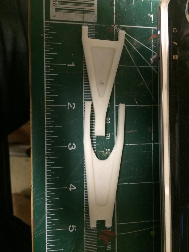
The retract slider is printed. This thing is 3/8" in diameter and has a 10-32 tapped hole in it for the cylinder rod. The bolt is just to make moving it easier since i dont have the cylinder on hand. Any actuator with a 2" strong and with a diameter or max width of 7/8" will fit within the frames. Electric versions should be a piece of cake!
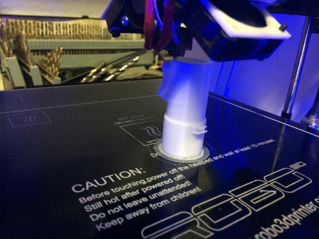
The first half of the upper landing gear strut is printing now, i had to split it in half due to it being 286mm long (11.25")... Now i am going to promptly make sure the strut is sized properly. Lol

The first half of the upper landing gear strut is printing now, i had to split it in half due to it being 286mm long (11.25")... Now i am going to promptly make sure the strut is sized properly. Lol

 08-13-2014, 10:44 PM
#35
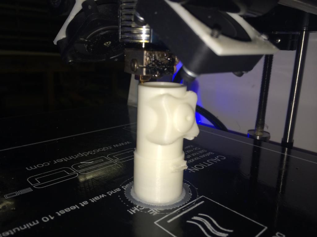
I had a slight blowout with the firsr attempt at the top half of the upper strut do to the thing popping off the build platform and turning into plastic spaghetti, so here is attempt two. The door attachment bosses didnt turn out as nice on this one because i turned the speed up to turn the 6 hour print into a 4 1/2 hour print.


 08-14-2014, 08:11 AM
#37
Attempt #2 was a failure.. I woke up around 9 expecting an email saying the print was done only to fine no email.... Apparently my computer restarted around 2:30-3am and locked up the system... Its time to get the LCD display so i can print away from the computer now... Luckily its only like $2 in materials..
08-14-2014, 07:36 PM
#38
Senior Member
Attempt #2 was a failure.. I woke up around 9 expecting an email saying the print was done only to fine no email.... Apparently my computer restarted around 2:30-3am and locked up the system... Its time to get the LCD display so i can print away from the computer now... Luckily its only like $2 in materials..
So I take it when you have a power outage the printer cannot begin where it left off?
How much can you print with one of the $40 spools?
That is so cool being able to mock up all kinds of parts if something's not right you can change it before a piece is actually machined!
08-14-2014, 07:40 PM
#40
Attempt #3... Fail. ABS plastic sucks to print with as it is a bit of a bear to keep it stuck to the build plate... So i cut the strut into three different pieces and 4" tall instead of two 6"ish pieces. The upper 4" is printing now, but while I modifed the print files, i printed the scissor links.. I already had to make one change to the lower scissor link, this is what makes the 3D printer worth it.
 08-15-2014, 09:54 PM
#41
I'm doing a kickstarter on some things (flush rivet burners, How to DVD's, 152 Shortkits) any help you guys may or may not be interested in providing would be appreciated
https://www.kickstarter.com/projects...r-a-1-4-ta152h
https://www.kickstarter.com/projects...r-a-1-4-ta152h
 08-23-2014, 07:24 PM
#43

My Feedback: (5)
Hi invertmast,
Were you planning to machine your own metal gear from your printed mock-ups? Or were you planning to out-source the job? If the latter, when you're ready to go from proto-type to production versions, I have some credit with a good machinist I can use to get a good start on a set. LMK if you're interested and I'll get some more details.
Were you planning to machine your own metal gear from your printed mock-ups? Or were you planning to out-source the job? If the latter, when you're ready to go from proto-type to production versions, I have some credit with a good machinist I can use to get a good start on a set. LMK if you're interested and I'll get some more details.
08-25-2014, 11:38 AM
#44
Hi invertmast,
Were you planning to machine your own metal gear from your printed mock-ups? Or were you planning to out-source the job? If the latter, when you're ready to go from proto-type to production versions, I have some credit with a good machinist I can use to get a good start on a set. LMK if you're interested and I'll get some more details.
Were you planning to machine your own metal gear from your printed mock-ups? Or were you planning to out-source the job? If the latter, when you're ready to go from proto-type to production versions, I have some credit with a good machinist I can use to get a good start on a set. LMK if you're interested and I'll get some more details.
08-27-2014, 12:12 PM
#45
Invert, have you ever used Carbon fiber or fiberglass tissue? I just saw this as a new product from ACP composites. I was wondering if there were any advantages or disadvantages to using it over regular glass cloth? It seems that it may be easier to deal with from a fraying standpoint, and would be easier to cut. I am thinking about getting some to test.
08-27-2014, 12:52 PM
#46
Invert, have you ever used Carbon fiber or fiberglass tissue? I just saw this as a new product from ACP composites. I was wondering if there were any advantages or disadvantages to using it over regular glass cloth? It seems that it may be easier to deal with from a fraying standpoint, and would be easier to cut. I am thinking about getting some to test.
Overall, if you have a non structural part that you would like to add some stiffness to (gear doors, fiberglass fuse sub formers that just keep you from collapsing the sides, etc) i would use it again, anything that needs strength added, i would look elsewhere.
09-08-2014, 11:51 AM
#47
I'm slowly working on things for the TA while i finish up the pancakes..
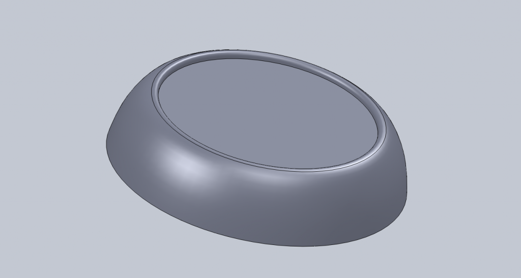
Here is a shot of the Cowl Nose ring drawn in Cad. This will be cut into four sections (so it will fit my print area) and 3D printed. It will then be glued to the wooden cowl ring section of the cowl, glassed and all the panel line stuff done.
And for those wondering, the shape of this part is 100% accurate as I used original Focke Wulf factory drawings to draw this part.
 09-08-2014, 06:35 PM
#49
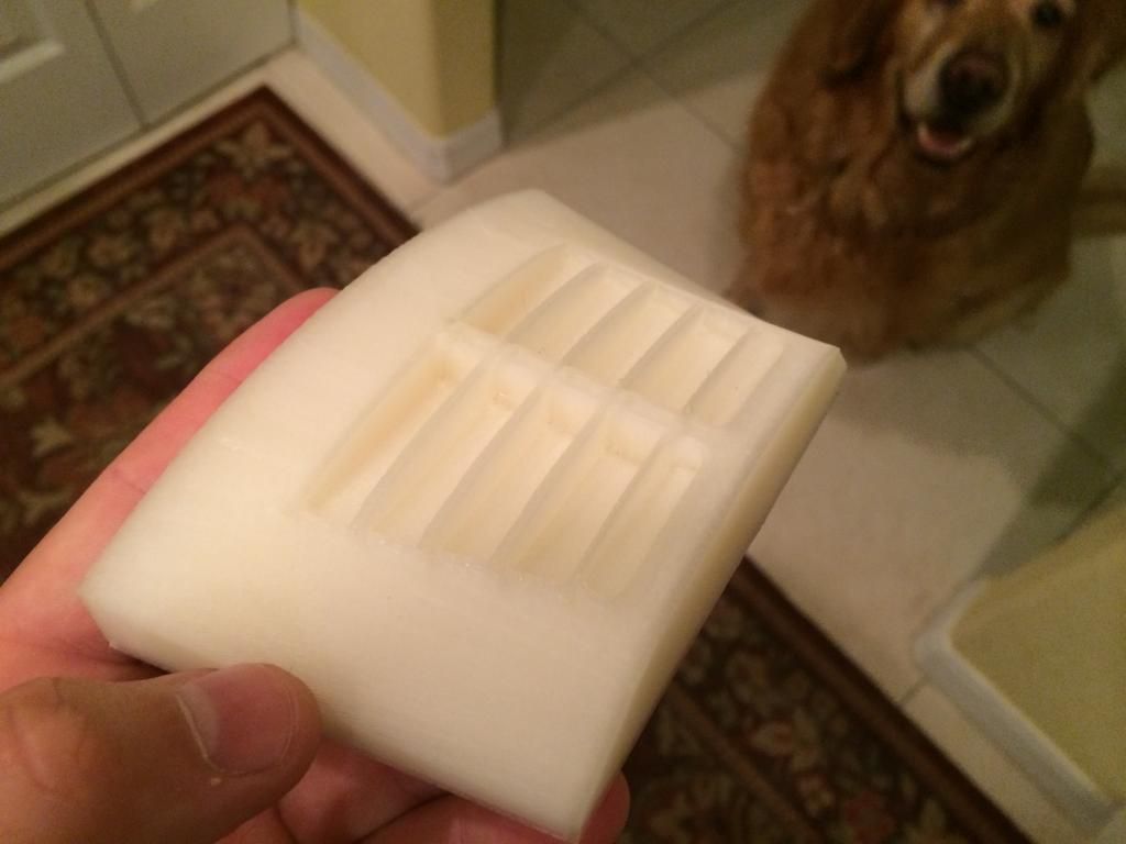
The first part of the top cowl louvers has been printed. I need to correct the louver cutouts now with some extra parts to be printed out and glued in to give it that "ramp", then this part will be done.
The aft side isnt a perfect arc like the front, this was verified with actual focke wulf drawings as well.
The aft side isnt a perfect arc like the front, this was verified with actual focke wulf drawings as well.

