


125% (1/4 scale) Anderson TA-152H


 12-09-2014, 10:36 PM
#128


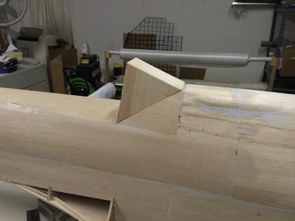
I finished the base plate on the gunhood. I then built up the fuselage infront of the gunhood so as to allow it to be faired into the fuse.
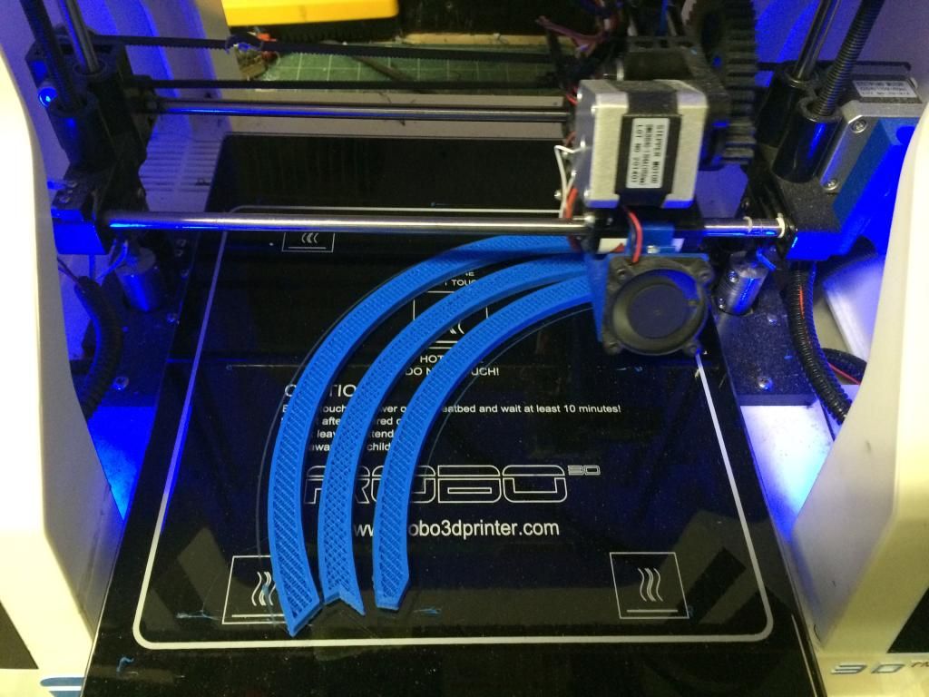
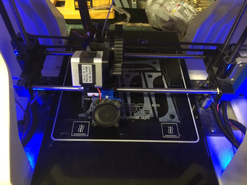
I also drew up the Cad model for the fuselage ring and started printing that. All but a 4" wide section is 3D printed, this 4" section wil be carved balsa due to the unique shape of this area due to the transition to the vents on the cowling.
I also cut out quick, crude windscreen. The actual windscreen will be CNC cut G10 pieces.

I also drew up the Cad model for the fuselage ring and started printing that. All but a 4" wide section is 3D printed, this 4" section wil be carved balsa due to the unique shape of this area due to the transition to the vents on the cowling.

I also cut out quick, crude windscreen. The actual windscreen will be CNC cut G10 pieces.

 12-10-2014, 02:58 PM
#129
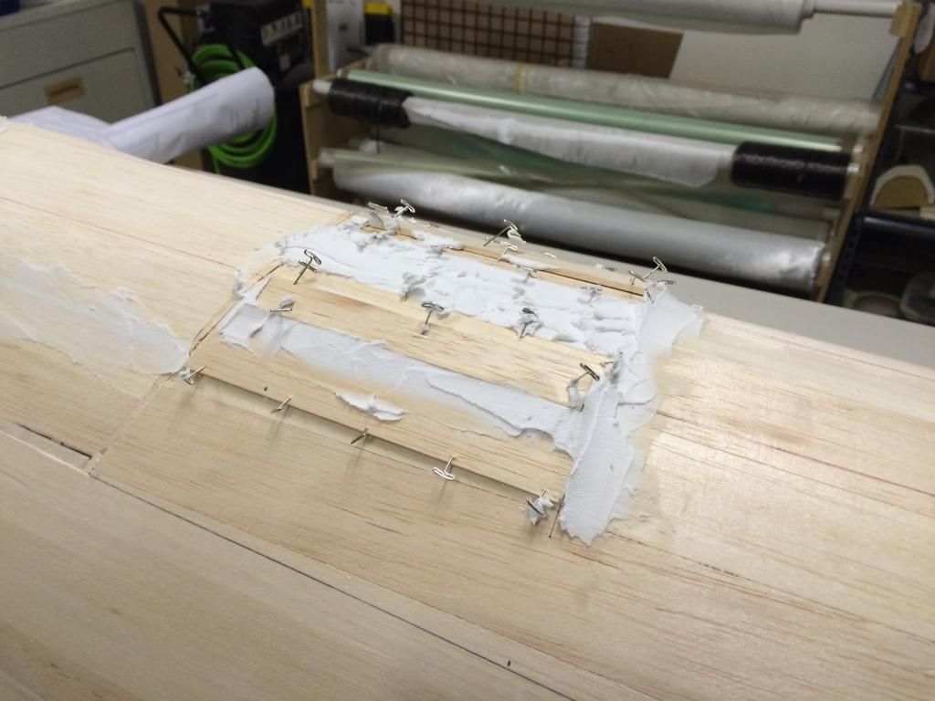
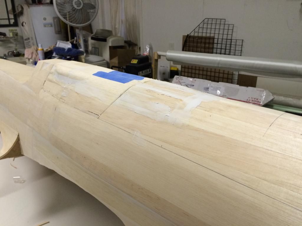
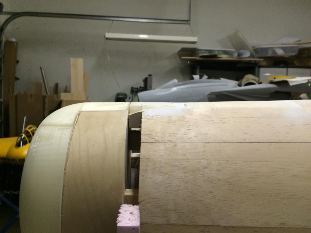
The gunhood fairing on the panel above the engine was roughed in. Now some filler is drying and then i'll finish it off.
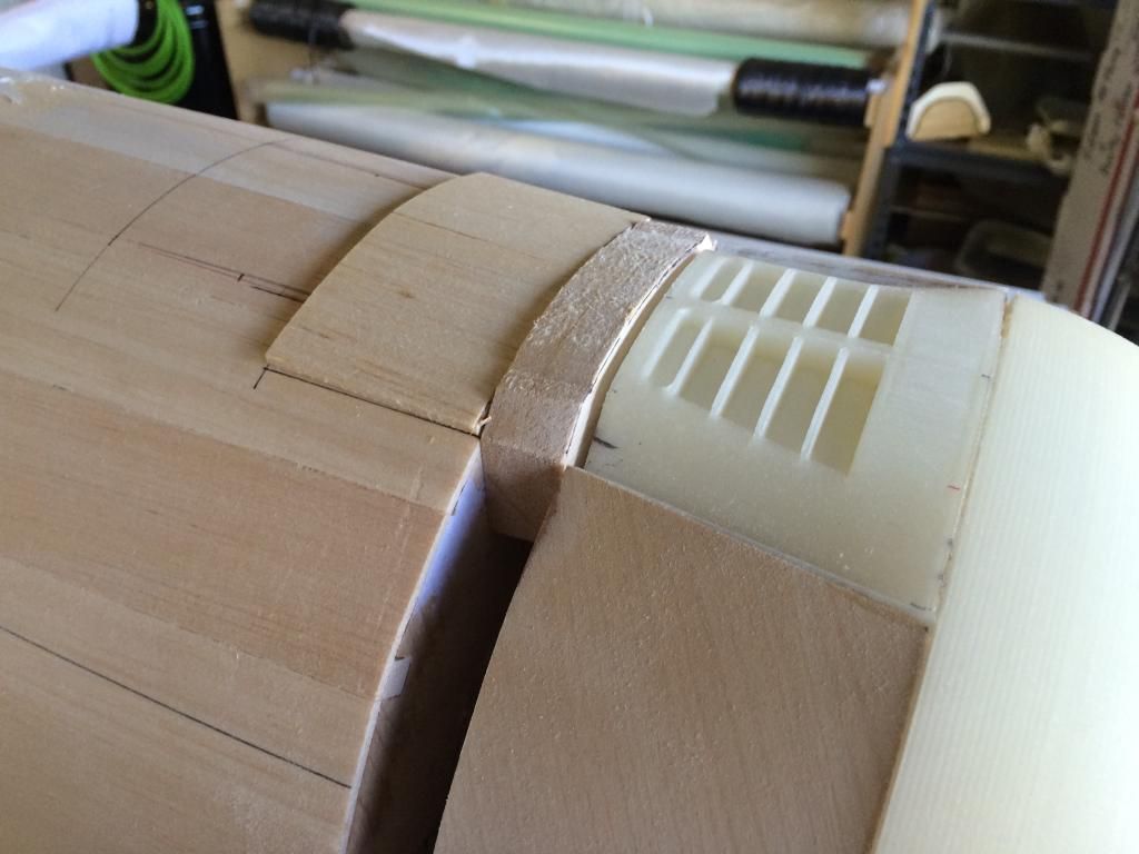
the filler block between the cowl vent and fuselage was cut and some filler pieces of balsa glued in place with wood glue.
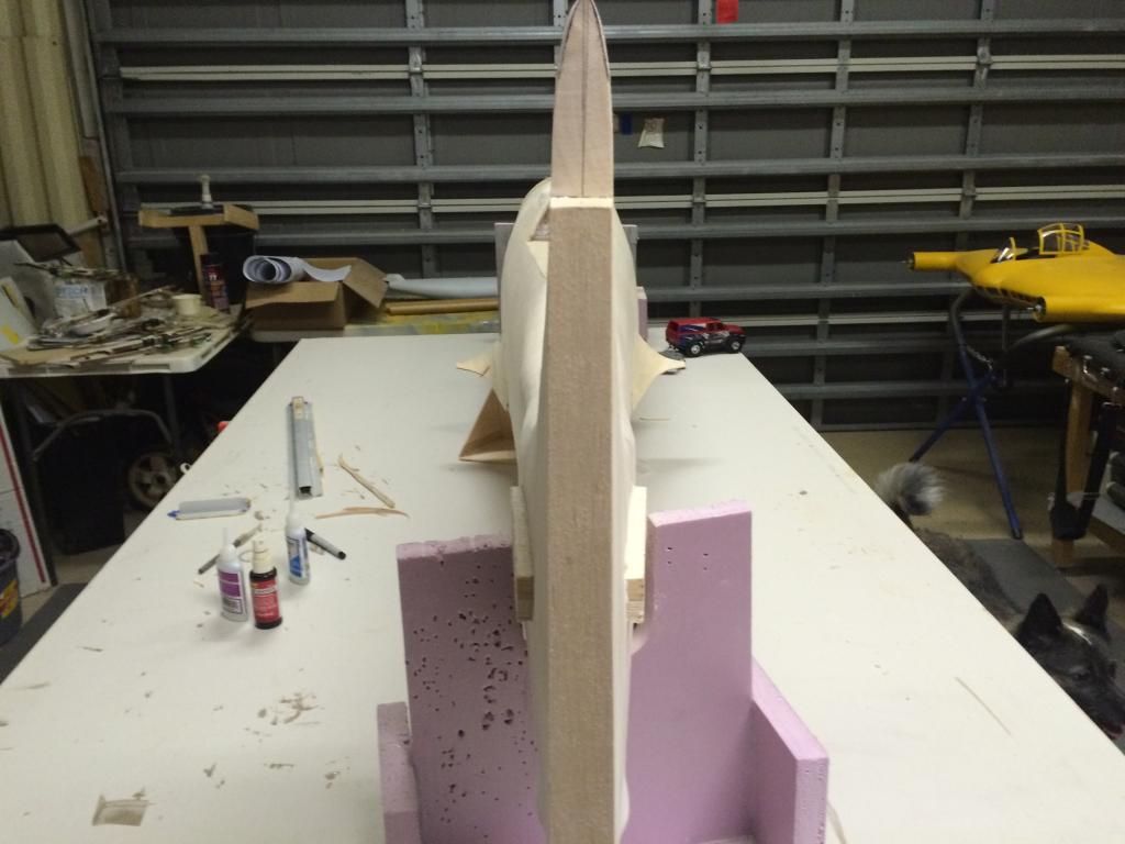
the tip of the vertical fin was also final shaped and the top skins of the wing fillets aft of the wing TE were installed.

the filler block between the cowl vent and fuselage was cut and some filler pieces of balsa glued in place with wood glue.

the tip of the vertical fin was also final shaped and the top skins of the wing fillets aft of the wing TE were installed.
 12-10-2014, 07:25 PM
#130
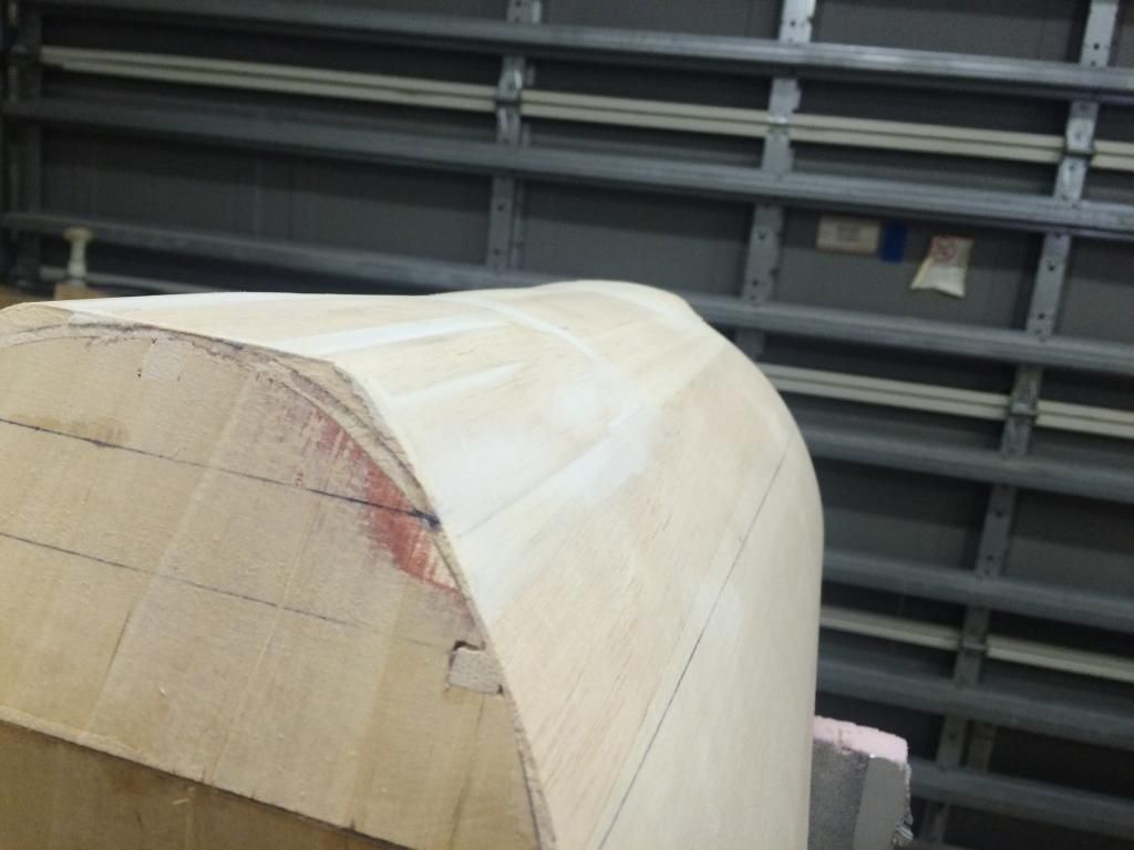
Cowl vent fairing has been shaped and the filler put on to help make the blend nice and smooth.
And a side shot. It is hard to see, but you can barely makeout how the fuselage begins to curve in and the fairing being slightly proud of that.
The gun hood fairing and gun hood is now down being shaped. I am much happier with the shape of the gunhood now.
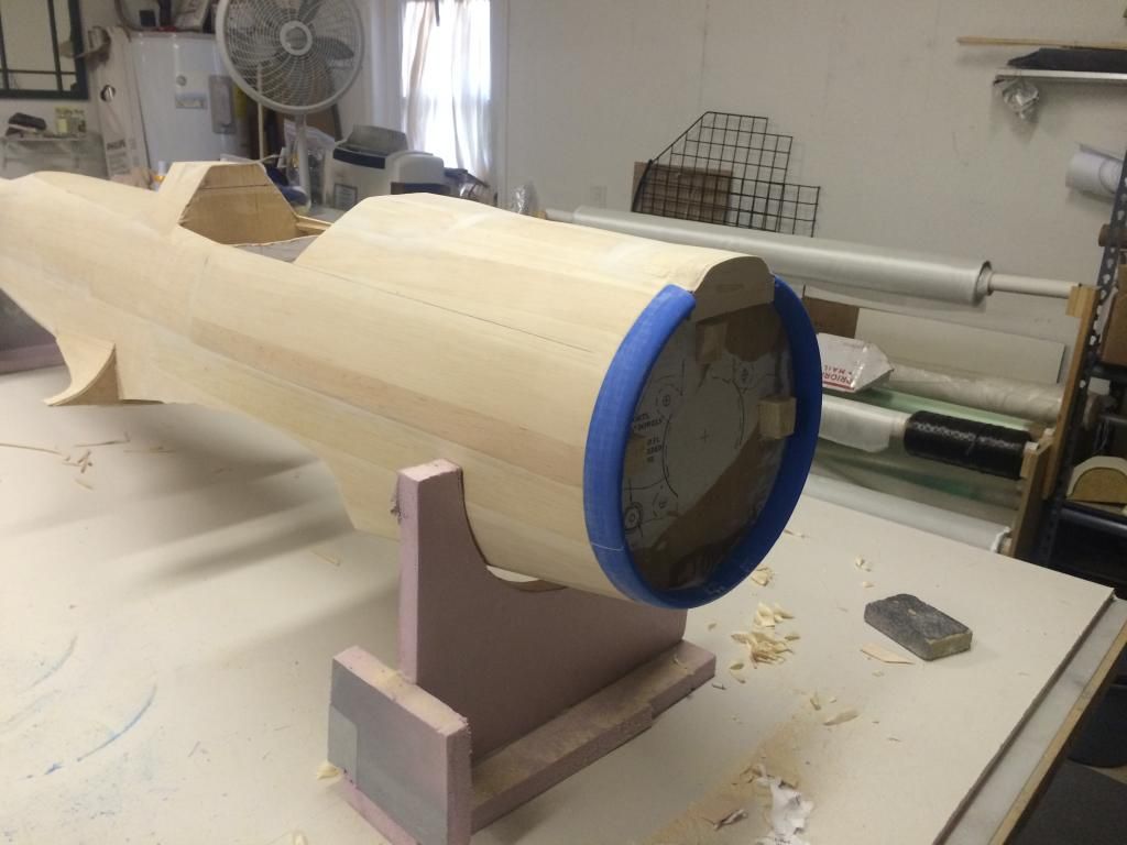
The 3D printed nose ring is done printing.
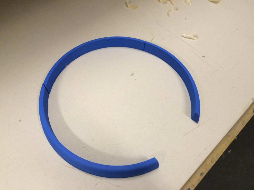
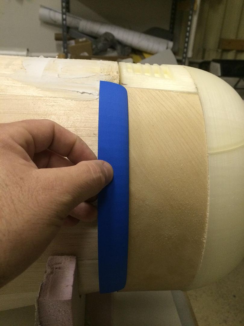
Here is a shot showing where its going. The whole purpose of this is to make a smooth lip to replicate the internal fairing that forces the cooling air through the radiator. The cowl flaps also rest on these in the fully closed position.

And a side shot. It is hard to see, but you can barely makeout how the fuselage begins to curve in and the fairing being slightly proud of that.

The gun hood fairing and gun hood is now down being shaped. I am much happier with the shape of the gunhood now.

The 3D printed nose ring is done printing.

Here is a shot showing where its going. The whole purpose of this is to make a smooth lip to replicate the internal fairing that forces the cooling air through the radiator. The cowl flaps also rest on these in the fully closed position.
 12-11-2014, 01:13 PM
#131
Alrighty.
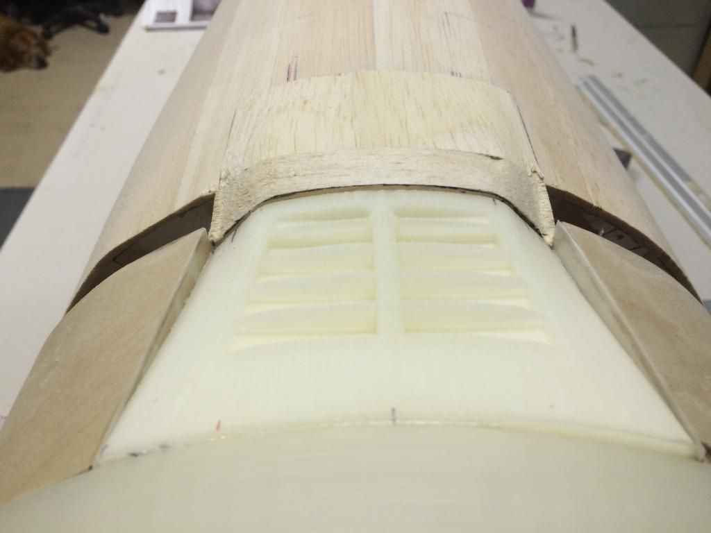
Cowl vent fairing is done, so the cowl plug was removed and the fuselage lip glued in place.
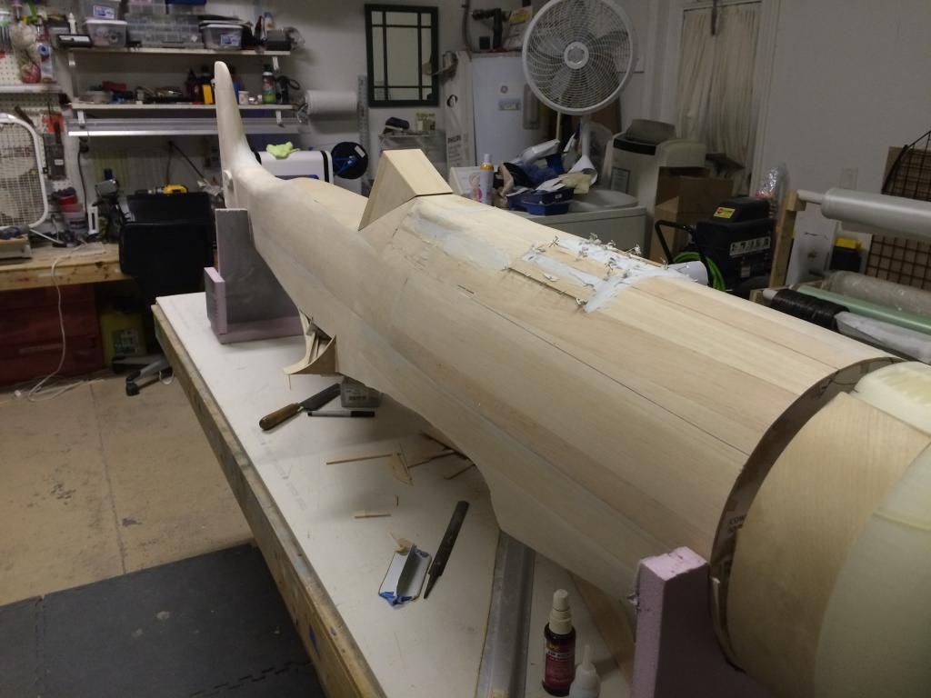
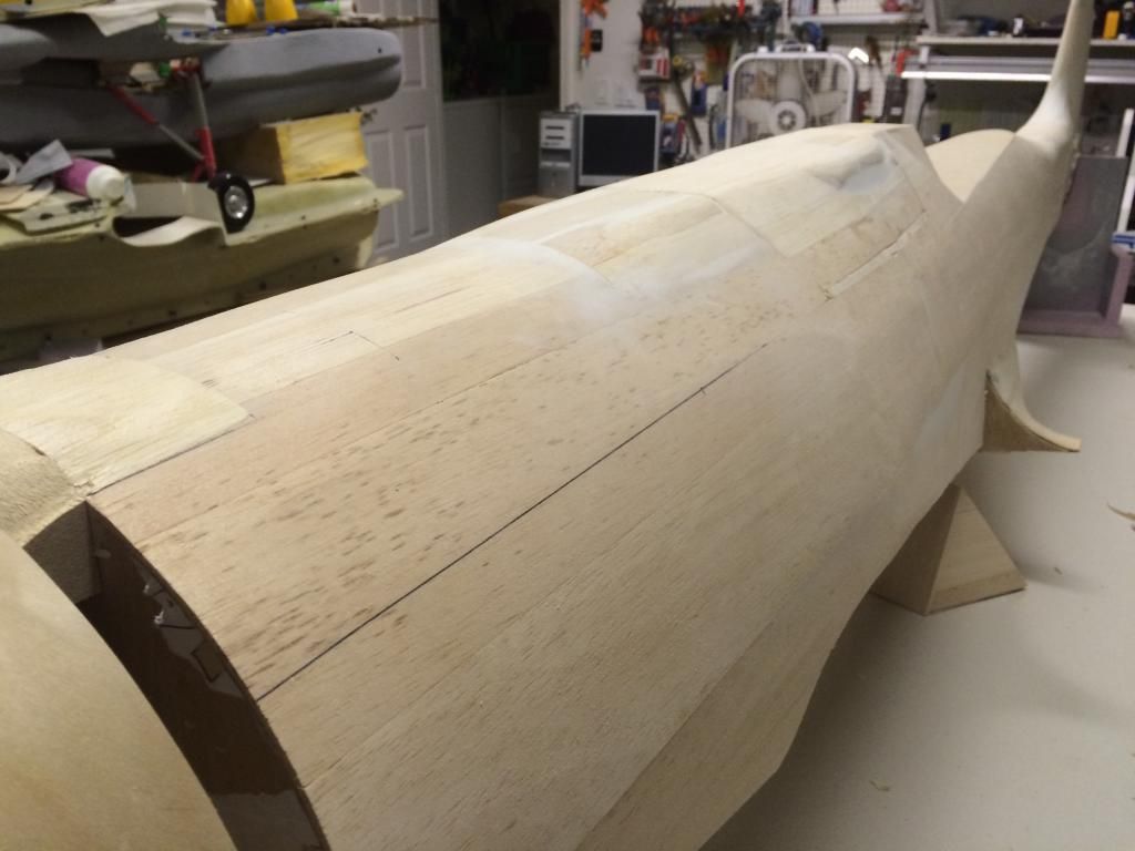
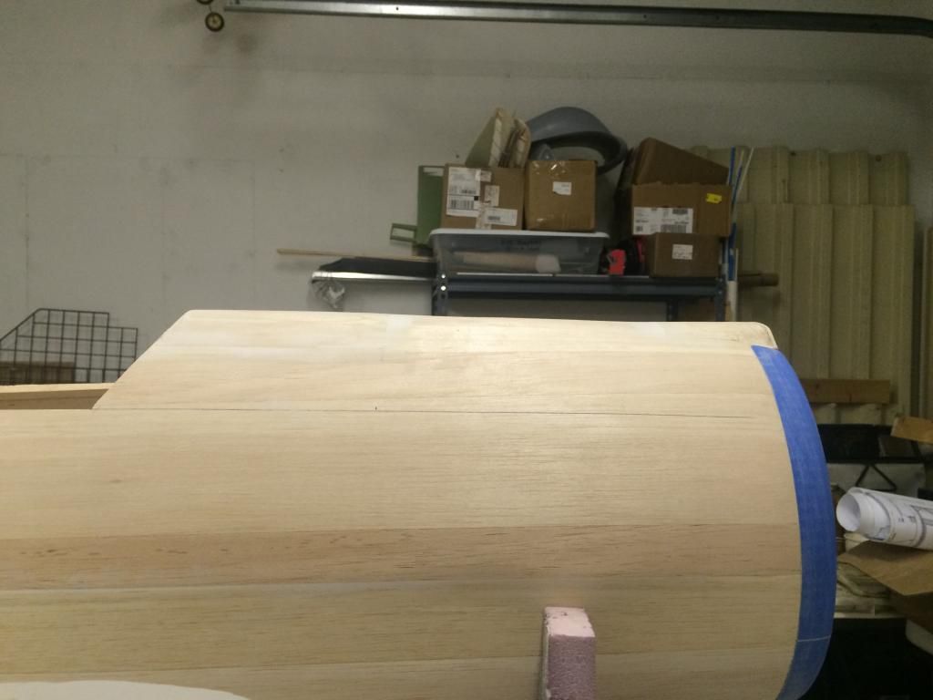
Here is a side view of the upper engine cowling. You can see it appears to have bulges, but is actually nearly perfectly flat.
And a view from the gunhood looking forward.
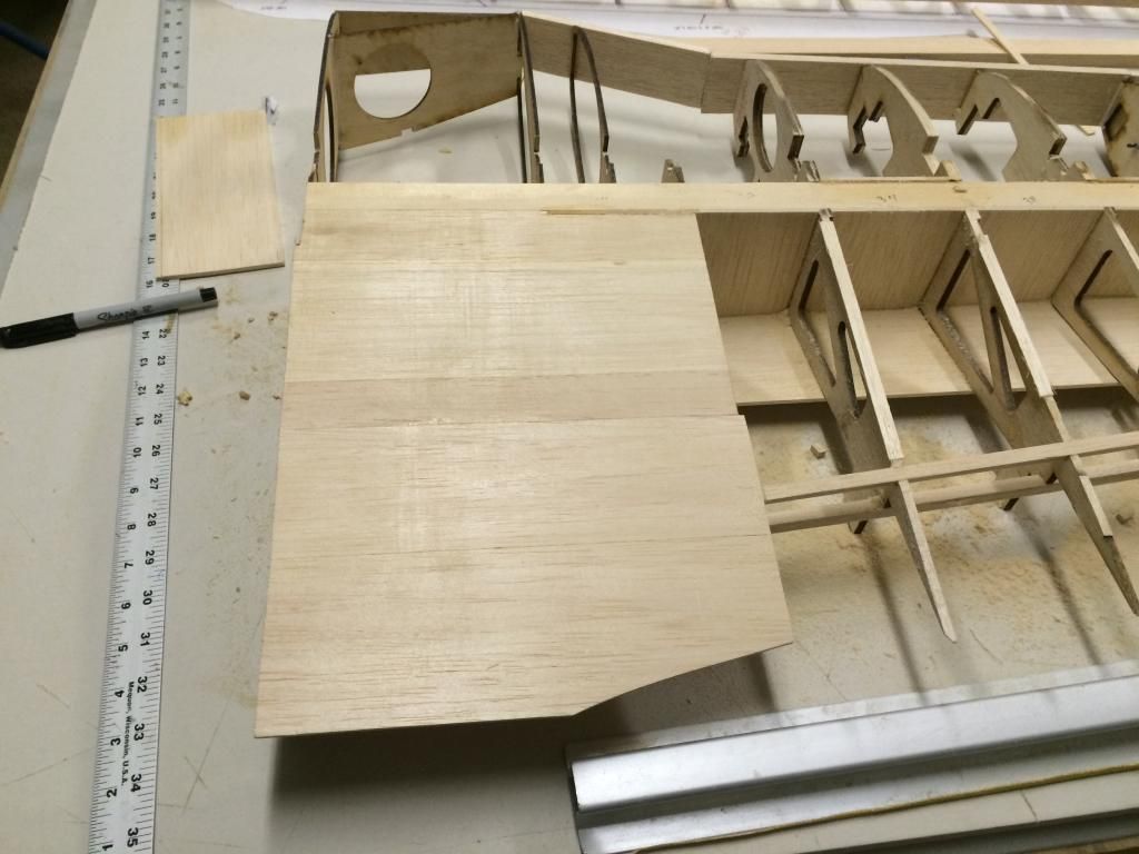
The corrected wing ribs arrived yesterday, so i glued the doublers on to those. Since the fuse is pretty far along, im switching gears to get the wings pretty far as well.
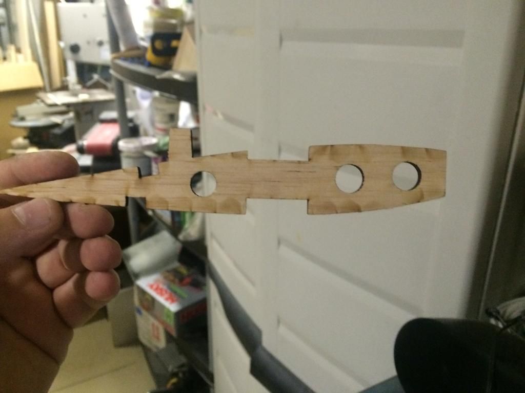
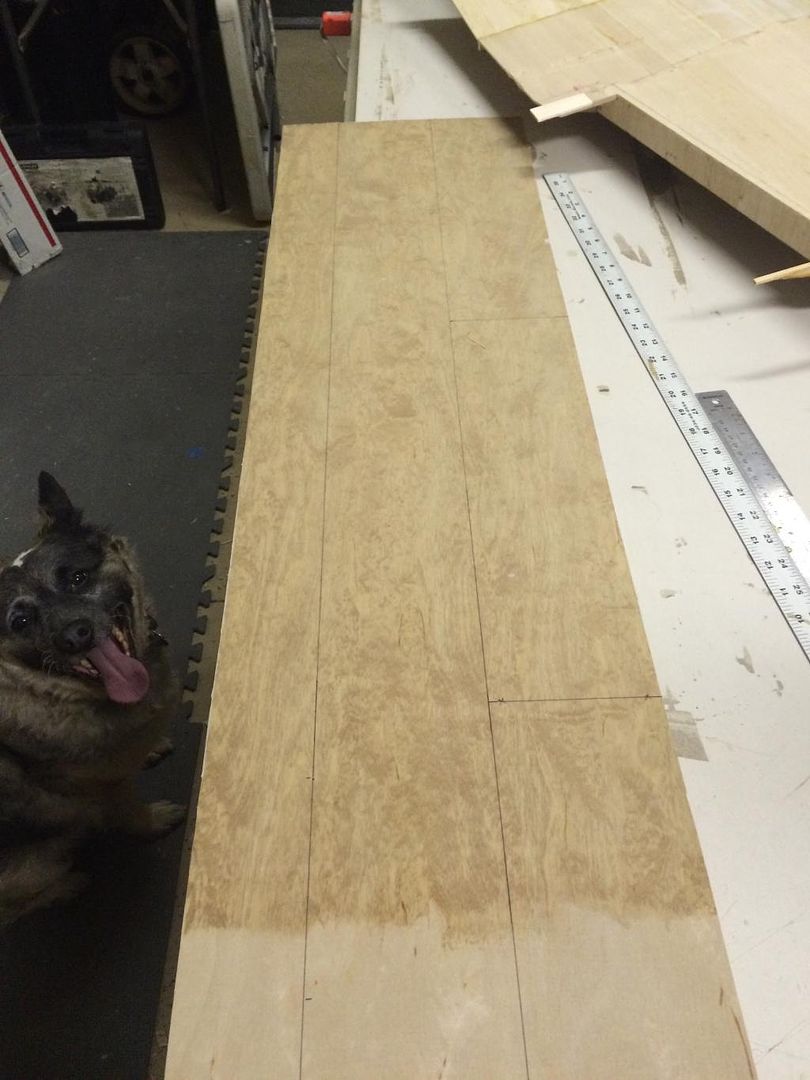
Someone asked about the airfoil at the tip, so here is a photo of the wingtip rib (its upside down btw)
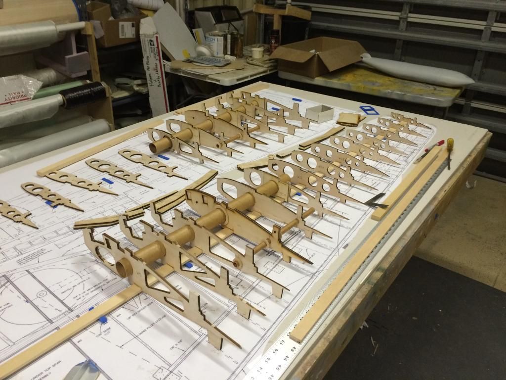
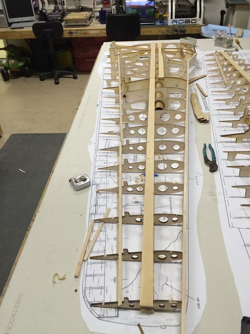
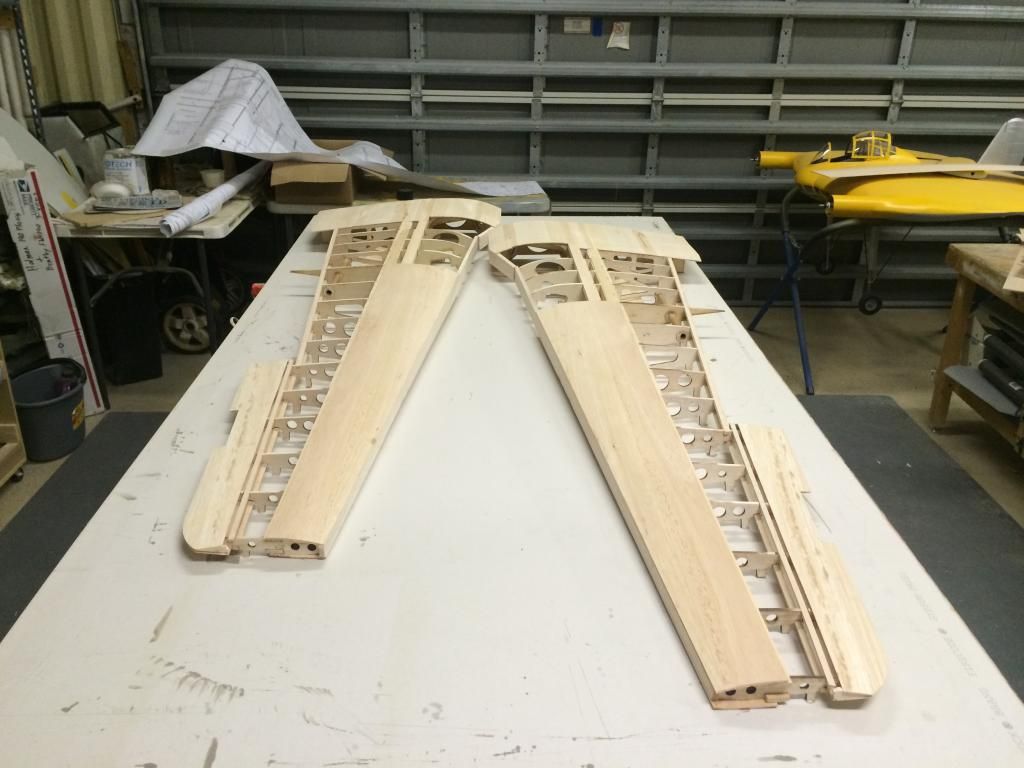
The wing plans and parts were then layed out on the table.
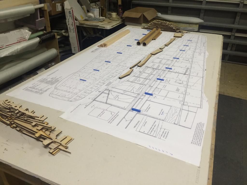
Then the 3D printed spar spacers were taped into place. I 3D printed the spar spacers because they are an odd thickness when you change the original thickness 125%.
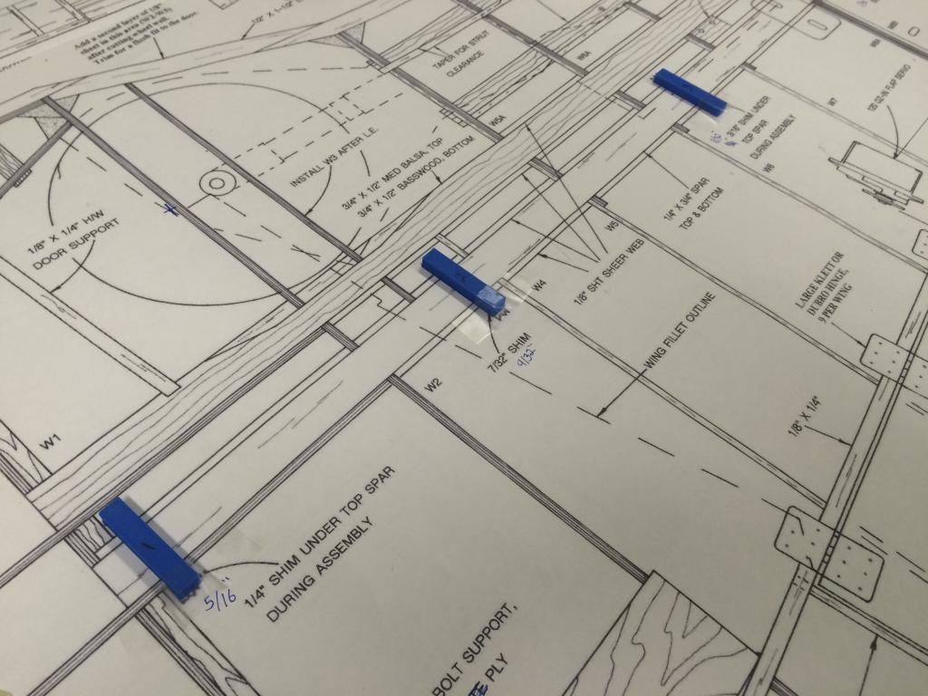
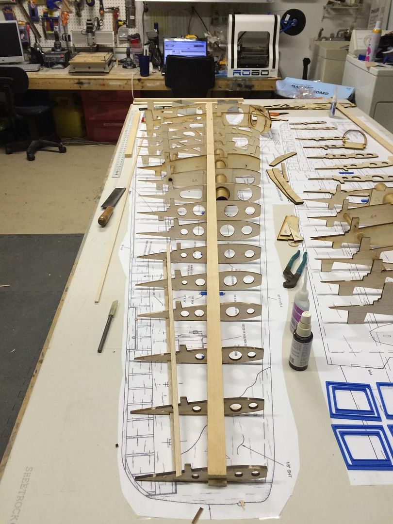
Then wing ribs from 5 to 10 were then put on the tube socket and 5 and 10 aligned to the leading edge and then pinned in place. The position of the 1/2" wing tube centerline was then transfered from the plans to ribs 7 to 9.
Cowl vent fairing is done, so the cowl plug was removed and the fuselage lip glued in place.

Here is a side view of the upper engine cowling. You can see it appears to have bulges, but is actually nearly perfectly flat.

And a view from the gunhood looking forward.

The corrected wing ribs arrived yesterday, so i glued the doublers on to those. Since the fuse is pretty far along, im switching gears to get the wings pretty far as well.
Someone asked about the airfoil at the tip, so here is a photo of the wingtip rib (its upside down btw)

The wing plans and parts were then layed out on the table.

Then the 3D printed spar spacers were taped into place. I 3D printed the spar spacers because they are an odd thickness when you change the original thickness 125%.

Then wing ribs from 5 to 10 were then put on the tube socket and 5 and 10 aligned to the leading edge and then pinned in place. The position of the 1/2" wing tube centerline was then transfered from the plans to ribs 7 to 9.
 12-11-2014, 06:43 PM
#132
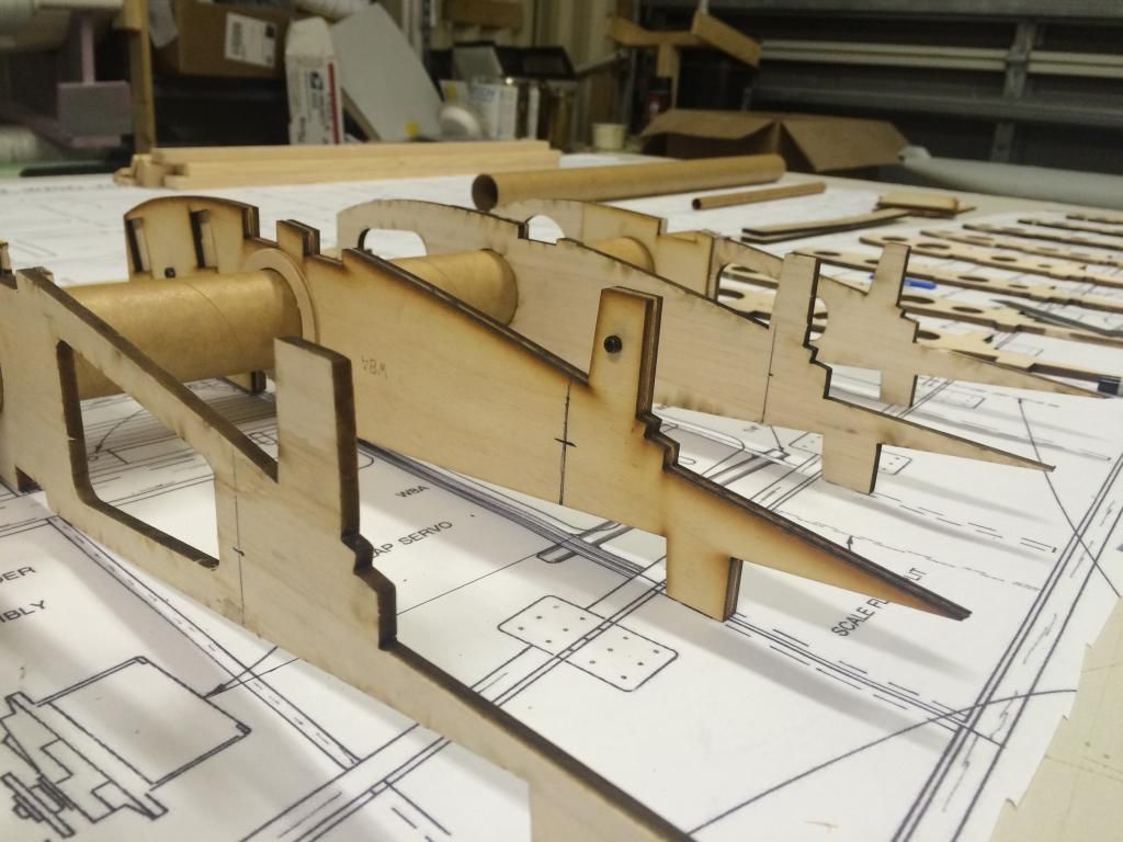
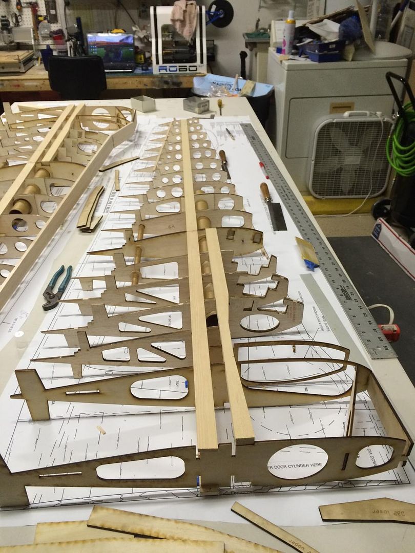
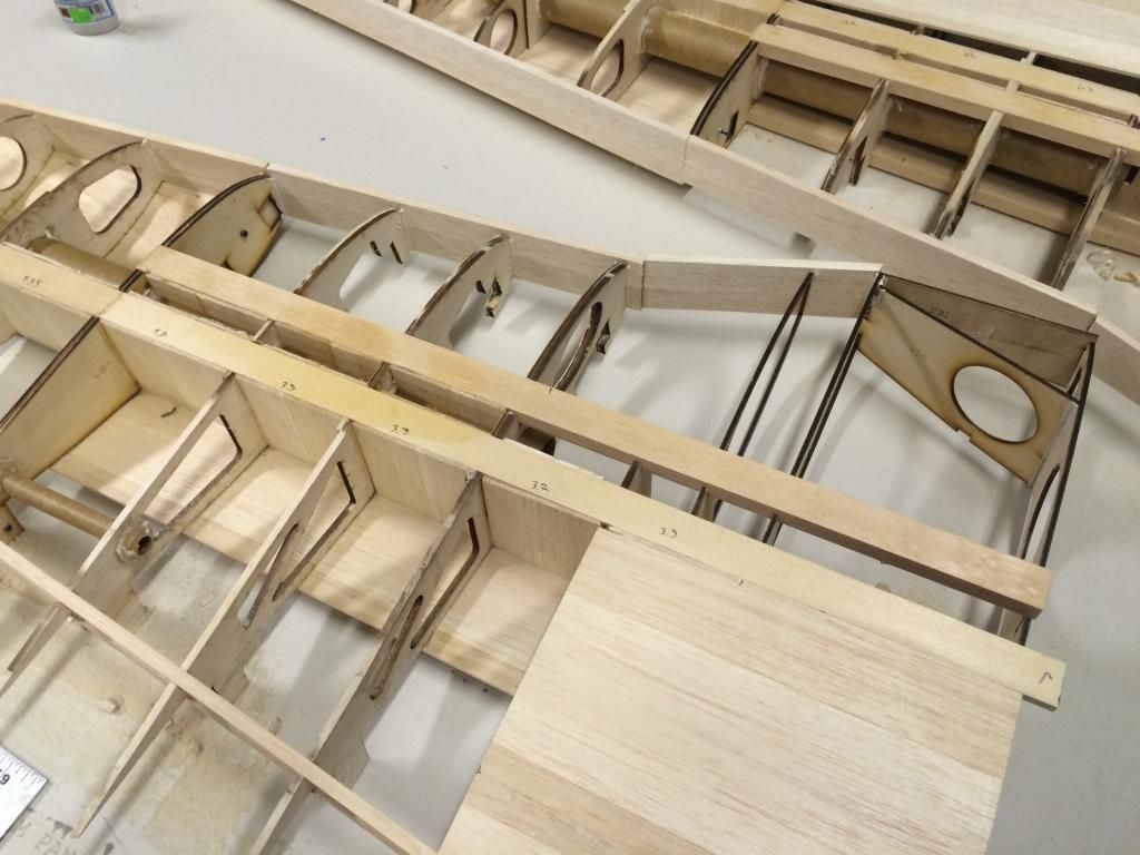
Now that the aft wing tube was located, the forstner bits were used to cut a 1/2" hole in the W7-9 wing ribs. This was then enlarged for the socket to slide through. Once done, the W5-10 wing ribs were slid onto the tube sockets.
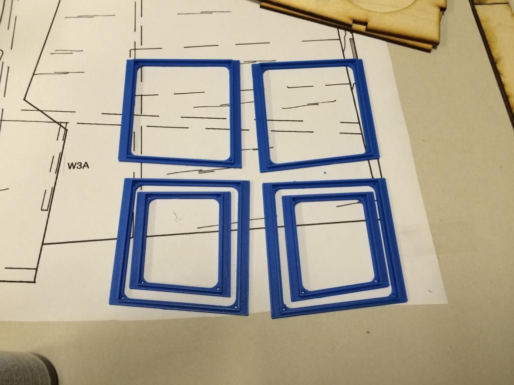
Then some 3D printed servo opening frames were printed. The actual covers will be printed later.
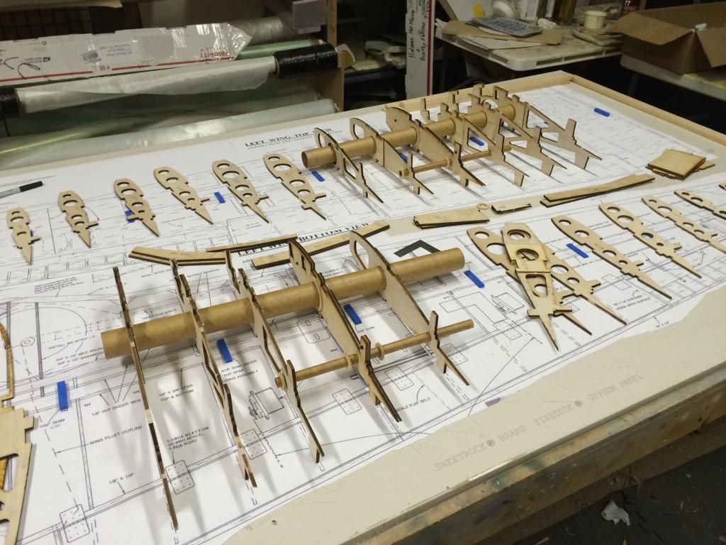
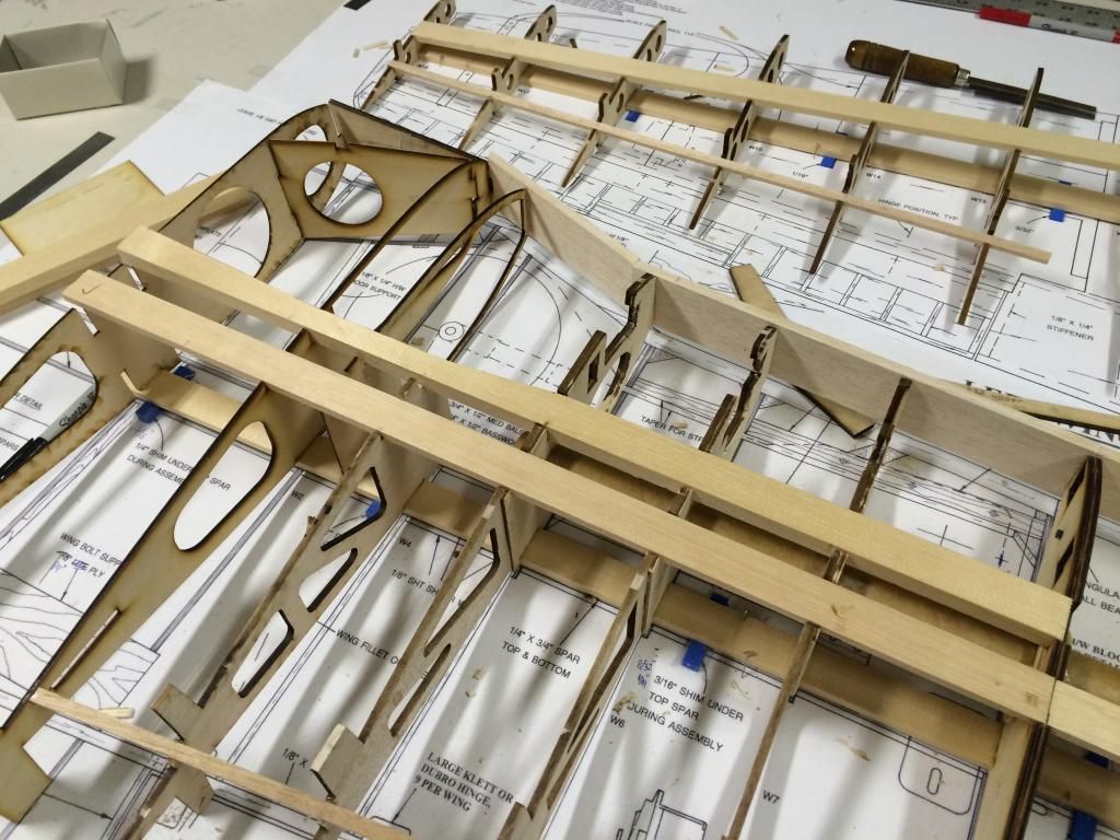
Then the wing ribs were positioned along the 1/4"x1" spruce main spar.
Once all the ribs were on the upper spar, the lower spar was put in place, along with the trailing edge stick at the Aileron LE.
Once all of the lower side stuff is done on this wing, I'll bring the other one up to the same stage.

Then some 3D printed servo opening frames were printed. The actual covers will be printed later.

Then the wing ribs were positioned along the 1/4"x1" spruce main spar.

Once all the ribs were on the upper spar, the lower spar was put in place, along with the trailing edge stick at the Aileron LE.

Once all of the lower side stuff is done on this wing, I'll bring the other one up to the same stage.
12-11-2014, 09:46 PM
#133
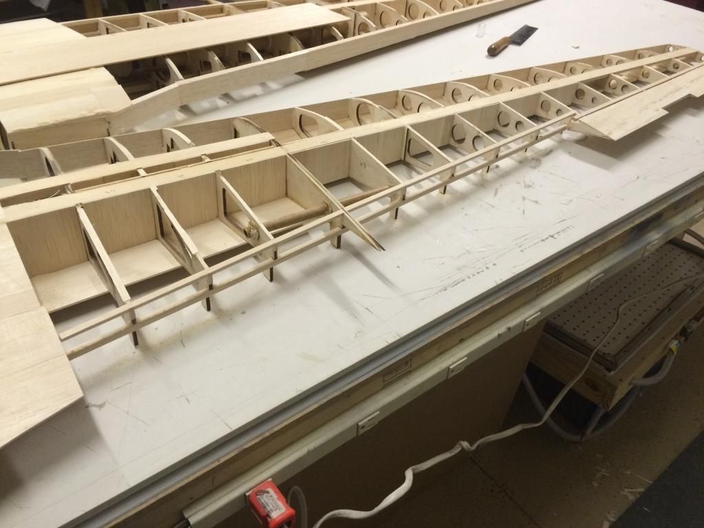
Got a bit more work done on the left wing panel. I installed the wing TE stringer at the flap LE. This was a pain. I replaced the 3/16x5/16 with a 5/16sq. This allowed me to set it into the ribs a bit more and gave me enough room to tack glue a straight edge down the length of it. I then used a straight edge on top of that to verify it was flat.
Then the 3/16" balsa false leading edge was installed along with the 1/2" x1" spruce center section spar.
The right wing panel was then started on. It is essentially at the same stage as the left other than the flap stringer and false leading edge.
These wings definitely aren't the easiest to build, but ive dealt with much worse.

Then the 3/16" balsa false leading edge was installed along with the 1/2" x1" spruce center section spar.

The right wing panel was then started on. It is essentially at the same stage as the left other than the flap stringer and false leading edge.

These wings definitely aren't the easiest to build, but ive dealt with much worse.
12-13-2014, 07:37 PM
#134
The aileron skins were installed. My original plan was 1/16" balsa skins and then a 1/32 ply laser cut piece that replicated the original structure glued over the top. But after getting the one panel flipped, im going to stick with my original plan of laser cut parts for the ailerons. The stock way of building these things is weird.
Another tip for building this thing. When the suggested builiding sequence says to install the aileron skins "top and bottom" dont install the top ones (the ones on the table top).
I also sheeted from the wing spar forward on the outer panel and a 6" wide section aft of the main spar on the inboard panel.
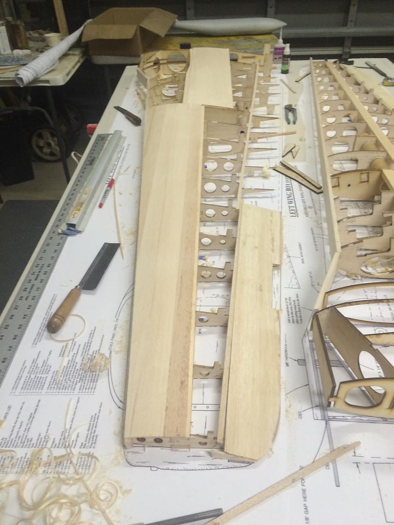
The wing was then removed from the plans and flipped right side up. The upper wing Te for the flap well was installed (this is an addon i made). The root was also sheeted from W1 to W4. The outer sheeting actually overlaps onto this area to butt up against the fuselage fillets.
Sheer webbing was added:
I also hysol'd the wing tube sockets to the wing ribs.
For those wondering about the wing in the Wing Te. Yes it is there. Unfortunately it is in the wrong spot. If built per the plans, the TE kink is just outboard of the gear door outer edge (right at rib W8, where the wing splits). From everything i have seen, it appears thd actual kink is supposed to be at the Flap/aileron split line.
If i can find a better photo of the real think showing the kink further outboard, ill just build a new set of outer wing panels. Or i'll just redesign the wing entirely as the way this thing is built is Really odd to me.
Another tip for building this thing. When the suggested builiding sequence says to install the aileron skins "top and bottom" dont install the top ones (the ones on the table top).
I also sheeted from the wing spar forward on the outer panel and a 6" wide section aft of the main spar on the inboard panel.

The wing was then removed from the plans and flipped right side up. The upper wing Te for the flap well was installed (this is an addon i made). The root was also sheeted from W1 to W4. The outer sheeting actually overlaps onto this area to butt up against the fuselage fillets.


Sheer webbing was added:


I also hysol'd the wing tube sockets to the wing ribs.
For those wondering about the wing in the Wing Te. Yes it is there. Unfortunately it is in the wrong spot. If built per the plans, the TE kink is just outboard of the gear door outer edge (right at rib W8, where the wing splits). From everything i have seen, it appears thd actual kink is supposed to be at the Flap/aileron split line.
If i can find a better photo of the real think showing the kink further outboard, ill just build a new set of outer wing panels. Or i'll just redesign the wing entirely as the way this thing is built is Really odd to me.
12-14-2014, 06:37 AM
#135

I like what is going on with this wing. The stick on the leading edge gives a good straight reference.
http://www.rcuniverse.com/forum/rc-w...l#post11937513
Building this wing was not hard, but getting it straight was. I think that some of the tabs are the wrong size. No way to know that though until you lift it off the board.
Another thing to watch, which may not matter since this one is not flying, are the angles of the maple retract rails. Mine are about 1/8" out. So, this causes the axles to not sit parallel with the ground. Also, the wheels go too far into the wing. A fairly easy fix, but something else to do.
12-14-2014, 07:50 AM
#136
I like what is going on with this wing. The stick on the leading edge gives a good straight reference.
http://www.rcuniverse.com/forum/rc-w...l#post11937513
Building this wing was not hard, but getting it straight was. I think that some of the tabs are the wrong size. No way to know that though until you lift it off the board.
Another thing to watch, which may not matter since this one is not flying, are the angles of the maple retract rails. Mine are about 1/8" out. So, this causes the axles to not sit parallel with the ground. Also, the wheels go too far into the wing. A fairly easy fix, but something else to do.
http://www.rcuniverse.com/forum/rc-w...l#post11937513
Building this wing was not hard, but getting it straight was. I think that some of the tabs are the wrong size. No way to know that though until you lift it off the board.
Another thing to watch, which may not matter since this one is not flying, are the angles of the maple retract rails. Mine are about 1/8" out. So, this causes the axles to not sit parallel with the ground. Also, the wheels go too far into the wing. A fairly easy fix, but something else to do.
The fuselage isnt flying, but the wings are. My retracts use a different mounting method than what is shown on the plans, so the vast majority if the structure forward if the spar and inboard of rib W7 will be removed for scale wheel well detailing.
Im also going to remove the wing dowels on the leading edge and use a ply tongue and receiver setup between the center section spars with some bolts that go through this into a pair of bulkheads in the fuse. This will essentially have four bolts holding it on instead of two and a pair of dowels in an area that has little structure to it.
As far as thd rib tabs, i agree, i believe some of them are off in size.
Once this one is built, i plan to go back and remove all of the tabs on the bottom of the wing and extend the upper ones while adding some to the leading edges as well. This will allow the wing to be built right side up and the entire top being able to be sheeted as well. If that is able to be done, then the wing will be pretty strong at that point and sheeting it and it remaining straight should be easier.
12-14-2014, 07:58 AM
#137
I agree on the sheeting and the basic construction process. Dave has you remove and flip the wing too many times before it is rigid. I would prefer to build the entire wing, right side up, then sheet most of it, before removing it from the board.
I would also add a 1/4" square sup leading edge to keep the ribs centered. This keeps everything lined up. My Ziroli Stuka is this way. Also, now that I have shaped the leading edge, I do not like having the sheeting extend over the L.E. I would rather have a solid L.E. stock to shape. So I would have a Sub- L. E., that gets sheeted over, then a main L.E. that would be glued on tying all of that structure together. This would give better material to shape.
I would also add a 1/4" square sup leading edge to keep the ribs centered. This keeps everything lined up. My Ziroli Stuka is this way. Also, now that I have shaped the leading edge, I do not like having the sheeting extend over the L.E. I would rather have a solid L.E. stock to shape. So I would have a Sub- L. E., that gets sheeted over, then a main L.E. that would be glued on tying all of that structure together. This would give better material to shape.
12-14-2014, 05:49 PM
#139
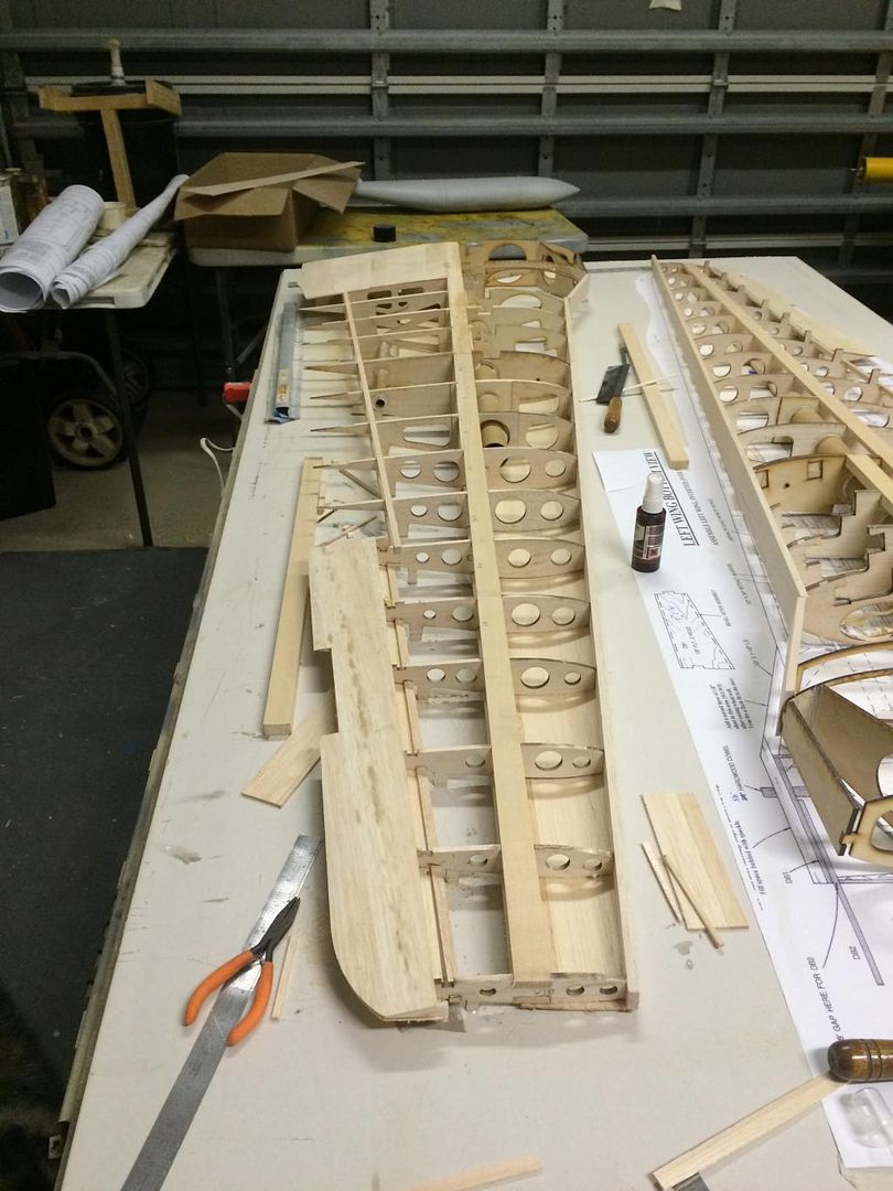
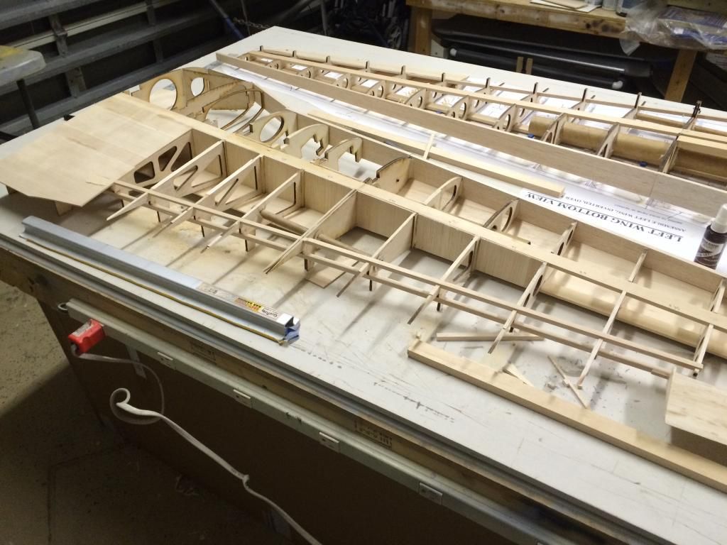
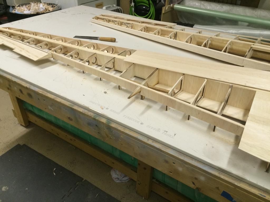
The left wing was brought up to the same completion level as the right and then flipped over on the build table.
The upper rear wing spar stringer was installed along with the sheer webbing.
The 1/2x1 spruce doubler spar in the center section was also installed and sheer webbed on both wings.
Then both wings has the spars trimmed down, the sub leading edge brought to the same level as the wing ribs and the inboard sheeting installed
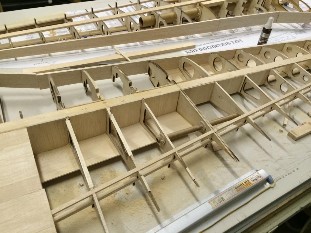
The flap well ribs were then cut off from the balsa ribs and sanded flush to the upper/lower rear spar stringers.
The rear spar stringers then had the rear side sheer webbed with 1/8" balsa with the grain oriented vertically.
Then the hardwood blocks dor the wing retention were installed. Originally i was going to go with merlyn locks, but i decided to go with a way that i typically use and will keep the wing retention bolts 100% hidden.
A hardwood block was epoxied to the outside of the W10 rin and to the spar. This was chosen because it was a snug fit between the wing tube socket and the wing skin. The is will get drilled and tapped for a 6-32 bolt to hold the wing tibe to the outer wing panel. The inboard wing panel had a hardwood block epoxed to W5 at an angle so that the bolt can be gotten to from inside the wheel well. This should allow easy access when the plane is on its gear.

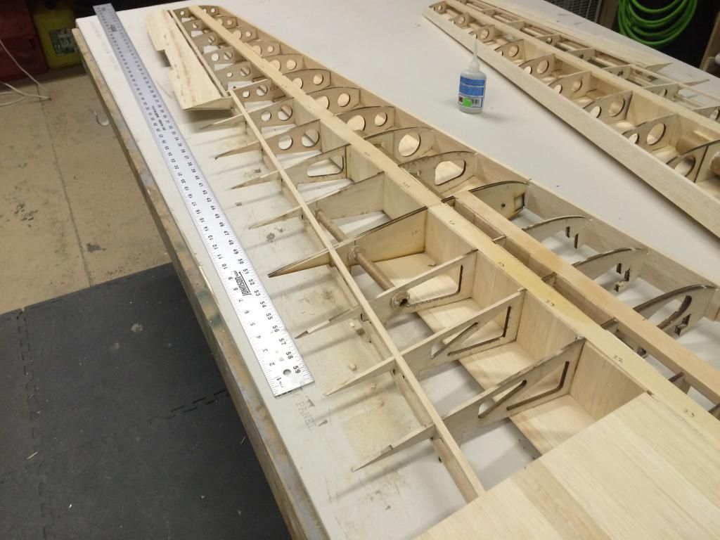
the Top of the outer wings forward of the wing spar were then sheeted.
at this point, both wings are at the same stage of completion and are very rigid. After i get done building a shipping crate tomorrow, ill get the last few things that need to be done prior to sheeting done.
The upper rear wing spar stringer was installed along with the sheer webbing.

The 1/2x1 spruce doubler spar in the center section was also installed and sheer webbed on both wings.

Then both wings has the spars trimmed down, the sub leading edge brought to the same level as the wing ribs and the inboard sheeting installed

The flap well ribs were then cut off from the balsa ribs and sanded flush to the upper/lower rear spar stringers.

The rear spar stringers then had the rear side sheer webbed with 1/8" balsa with the grain oriented vertically.

Then the hardwood blocks dor the wing retention were installed. Originally i was going to go with merlyn locks, but i decided to go with a way that i typically use and will keep the wing retention bolts 100% hidden.
A hardwood block was epoxied to the outside of the W10 rin and to the spar. This was chosen because it was a snug fit between the wing tube socket and the wing skin. The is will get drilled and tapped for a 6-32 bolt to hold the wing tibe to the outer wing panel. The inboard wing panel had a hardwood block epoxed to W5 at an angle so that the bolt can be gotten to from inside the wheel well. This should allow easy access when the plane is on its gear.

the Top of the outer wings forward of the wing spar were then sheeted.

at this point, both wings are at the same stage of completion and are very rigid. After i get done building a shipping crate tomorrow, ill get the last few things that need to be done prior to sheeting done.
12-16-2014, 05:15 PM
#140
The remainder of the top outer wing panels were sheeted.
Then the sheets for the main spar aft for the center section were made and joined. These are cut odd in th inboard ends as the fuselage fillets butt up against these skins. So for a small portion if the inboard wing panels. There is a double skin on the top.

Then the sheets for the main spar aft for the center section were made and joined. These are cut odd in th inboard ends as the fuselage fillets butt up against these skins. So for a small portion if the inboard wing panels. There is a double skin on the top.
 12-18-2014, 10:42 AM
#141
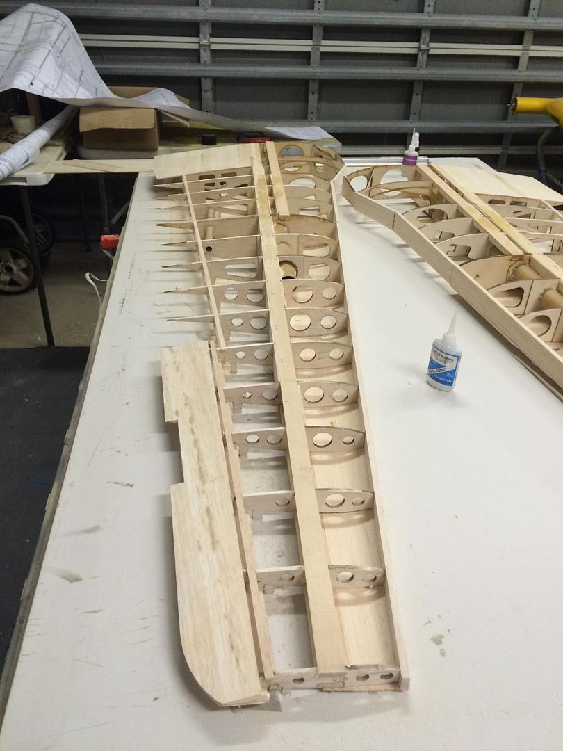
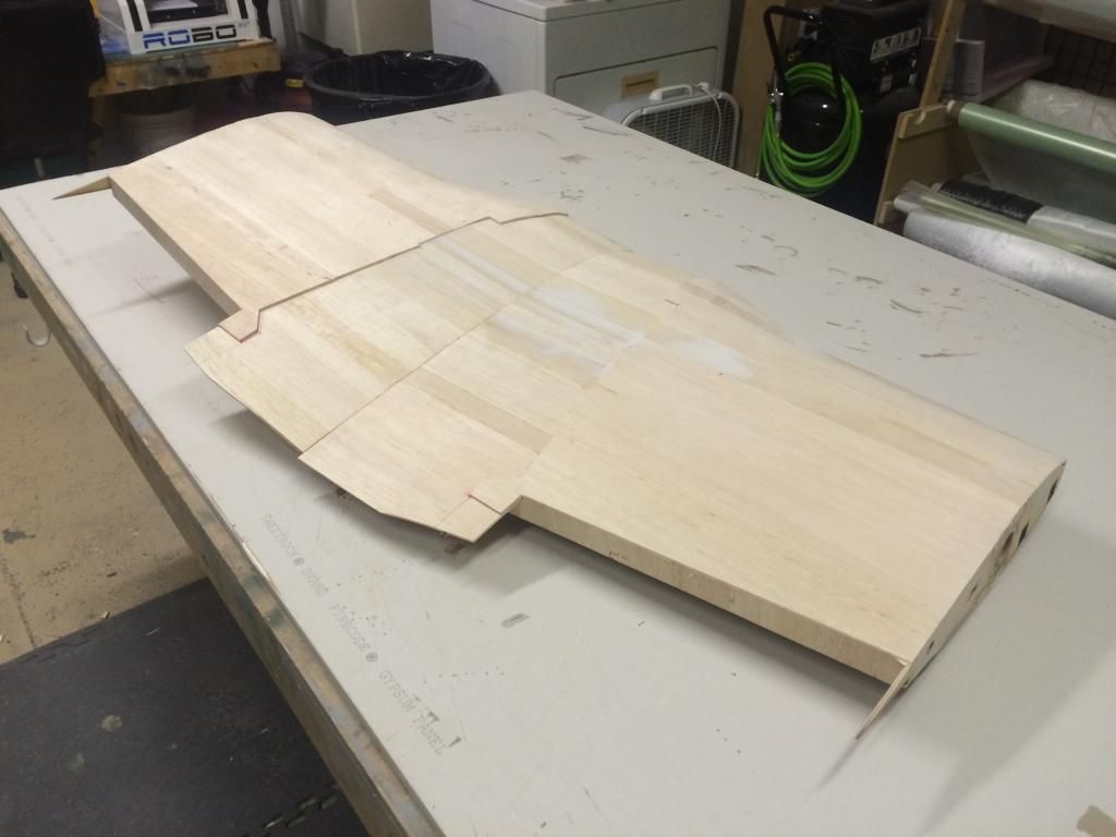
The tops of the wings are now sheeted.
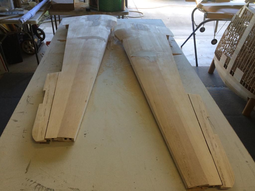
They were then removed from the building table. They are extremely strong at this point with no tendency to warp at all.
Now that i have built these wings more or less, here is what i would suggest.
Dont build the wings upside down, as the only reason i can justify for doing so originally is so the main landing gear rails can be installed. Build it right side up by spacing the wing spar off the building table the thickness of the wing sheeting. Then build the thing as you normally would. I would also suggest the rear spar sheer webbing like i did, even on the original version as it increases the torsional rigidity of the wing greatly. Then install a false leading edge, sheer webs, etc and sheet the entire top of the wing.
At this point the wing should be rigid enough to allow you to sheet the bottom without having to use the building tabs on the tops of the wing ribs.
Disclaimer: i havent done this yet, so before you glue it all together, i would check the incidence angles of the wing ribs to very that you are getting washout into the wings.
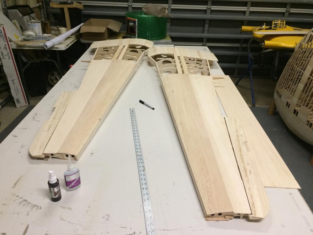
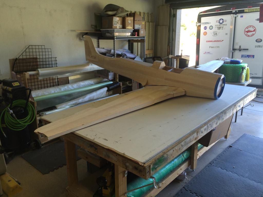
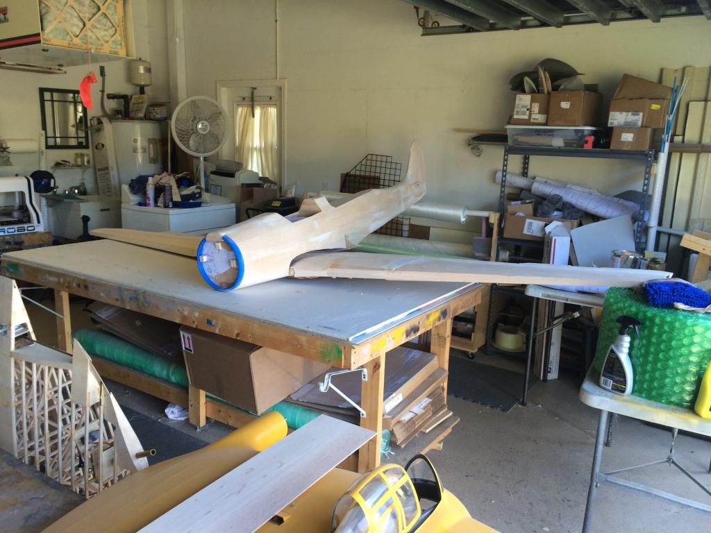
So. Now that the wings are off the table, i can build a shipping crate. But first, i had to get a few motivational shots (not like i needed them). As a reminder, that is a 4x8 foot table it is hanging over.

They were then removed from the building table. They are extremely strong at this point with no tendency to warp at all.
Now that i have built these wings more or less, here is what i would suggest.
Dont build the wings upside down, as the only reason i can justify for doing so originally is so the main landing gear rails can be installed. Build it right side up by spacing the wing spar off the building table the thickness of the wing sheeting. Then build the thing as you normally would. I would also suggest the rear spar sheer webbing like i did, even on the original version as it increases the torsional rigidity of the wing greatly. Then install a false leading edge, sheer webs, etc and sheet the entire top of the wing.
At this point the wing should be rigid enough to allow you to sheet the bottom without having to use the building tabs on the tops of the wing ribs.
Disclaimer: i havent done this yet, so before you glue it all together, i would check the incidence angles of the wing ribs to very that you are getting washout into the wings.
So. Now that the wings are off the table, i can build a shipping crate. But first, i had to get a few motivational shots (not like i needed them). As a reminder, that is a 4x8 foot table it is hanging over.

 12-18-2014, 04:52 PM
#142
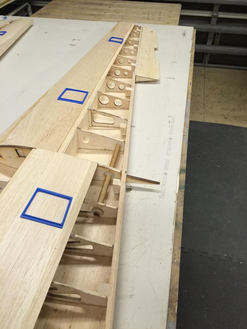
The hinge blocks for the flaps and ailerons were cut and glued in place. For hinges i'll be doing a bunch of CNC cut G10 pieces ghat will have the control horns integrated into them. The 3D printed servo hatch frames were also put in place. Ive got to route some strings for servo extension and then i can sheet the remainder of the bottom outboard wing panel. The inboard wont get finished until after i join the two halves.
 12-18-2014, 09:42 PM
#143
Outer wing panels are fully sheeted:
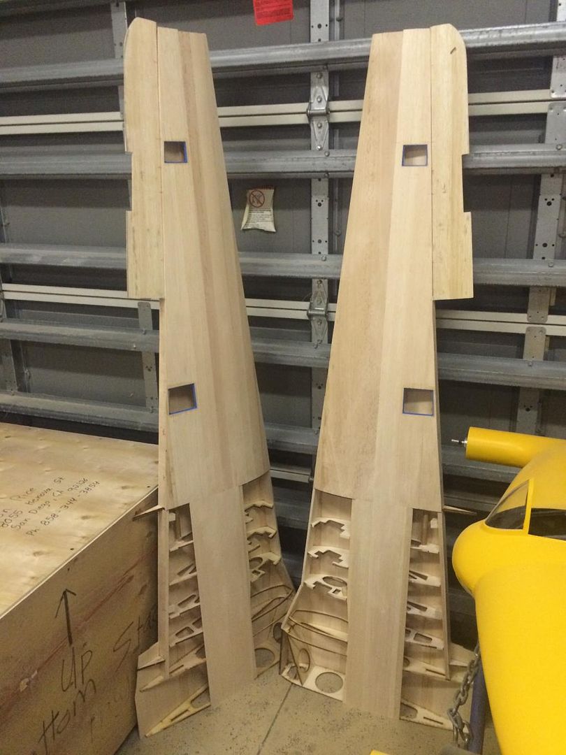
And then two, became four.
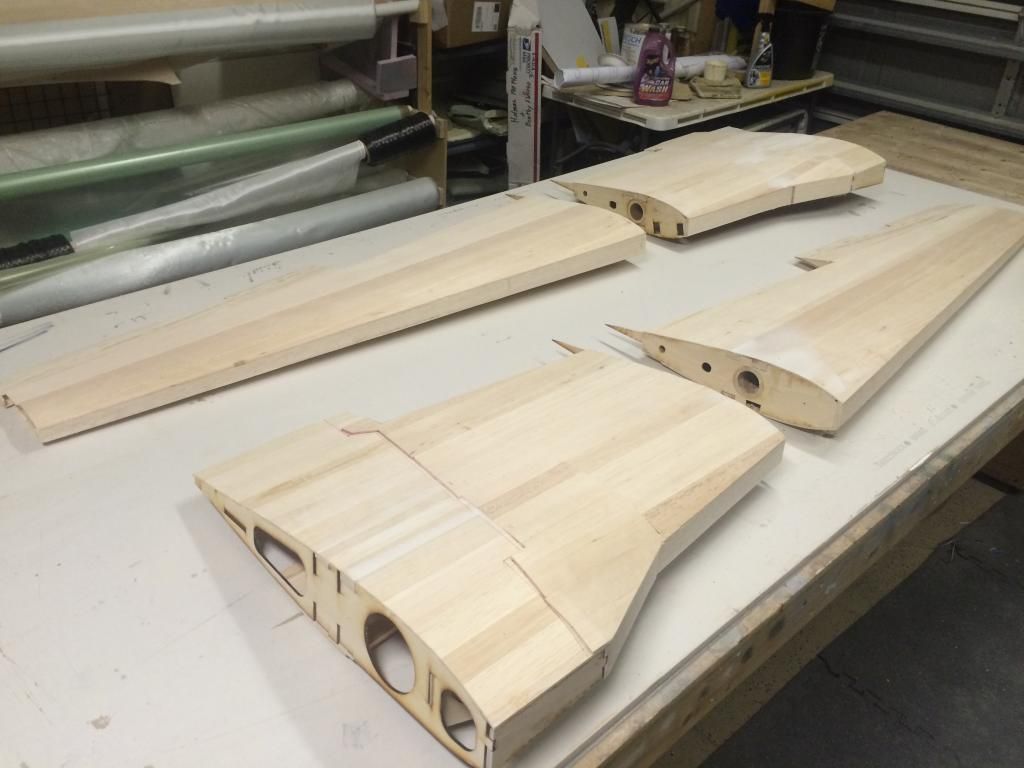
The six Dihedral braces were then test fit and the center sections clamped together are a little bit of fine tuning to get it all to go together smoothly.
Tomorrow i need to make up the rear wing bolt hold down plate and stiffeners. I also hope to get the forward wing bolt parts cut, then i can epoxy this whole thing together.

And then two, became four.

The six Dihedral braces were then test fit and the center sections clamped together are a little bit of fine tuning to get it all to go together smoothly.

Tomorrow i need to make up the rear wing bolt hold down plate and stiffeners. I also hope to get the forward wing bolt parts cut, then i can epoxy this whole thing together.
12-19-2014, 10:45 AM
#144
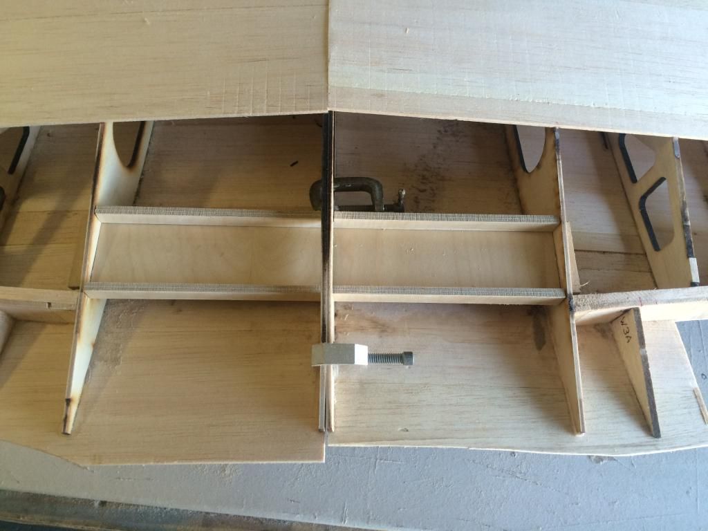
The rear wing bolt plate and stiffeners were cut and test fit.
Then the center wing halves were joined using this stuff.
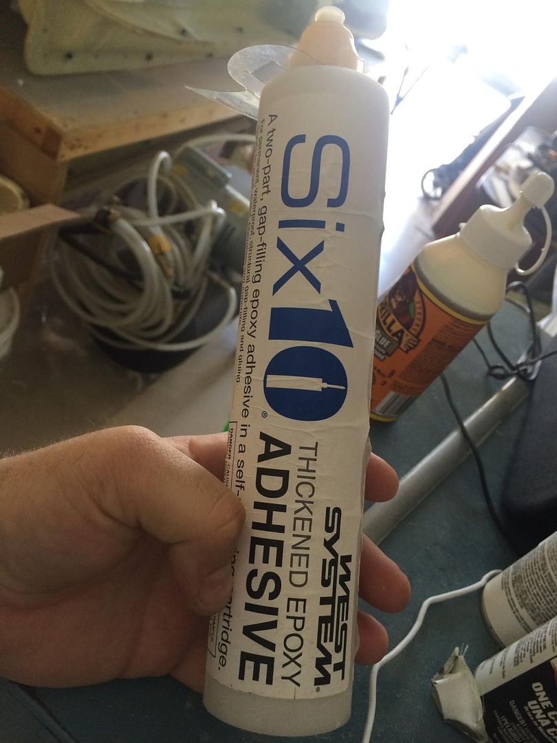
It is similar to Hysol In strength. The difference is, its a 190ml tube for $19. So you basically get 4 times more for the same price. It also uses a regular caulking gun. A 12 pack of nozzles are $20.
One cool thing about it, is it is thixotropic (doesnt sag) when it comes out of the gun, but if you work it with a mixing stick, it becomes more viscous over time. Pretty neat stuff.
Once all the parts and joints were covered in glue, it was all slid together and clamped. Then it was placed on the table with some scrap blocks elevating ribs 8 off the table. The incidence was then checked at each W8 rib. Both were identical, so this will be left to cure for the remainder of the day.
 12-21-2014, 03:34 PM
#145
Invert, I am wondering how to tackle the wing tube bolts. I was thinking of just drilling and tapping hardwood blocks, then allowing the screws to enter into holes in the tube itself. Essentially just preventing the tube from sliding or moving. I was only going to have a hole on one side of the tube. Never having a 3 piece wing before, I am wondering if this is OK, without weakening the tube?
12-21-2014, 04:42 PM
#146
Invert, I am wondering how to tackle the wing tube bolts. I was thinking of just drilling and tapping hardwood blocks, then allowing the screws to enter into holes in the tube itself. Essentially just preventing the tube from sliding or moving. I was only going to have a hole on one side of the tube. Never having a 3 piece wing before, I am wondering if this is OK, without weakening the tube?
Typically what i do is put the tube into the wing panel its going to stay in. Drill through the wood block and through the tube. Then tap both at the same time for whatever size bolt your planning on. Thin CA the wood block to harden the threads, tap again, then thin CA one more time. the wing tube now stays in this panel permanently. If not, you'll have a helluva time realigning the tube to the bolt hole.
Then for the other end, do the same thing.
I typically use 4-40 or 6-32 bolts on my stuff. I also try to keep the bolts as close to the ends of the tube as possible.
12-21-2014, 05:29 PM
#147
Yea you can drill the tube for a 4-40 or 6-32 bolt without worry.
Typically what i do is put the tube into the wing panel its going to stay in. Drill through the wood block and through the tube. Then tap both at the same time for whatever size bolt your planning on. Thin CA the wood block to harden the threads, tap again, then thin CA one more time. the wing tube now stays in this panel permanently. If not, you'll have a helluva time realigning the tube to the bolt hole.
Then for the other end, do the same thing.
I typically use 4-40 or 6-32 bolts on my stuff. I also try to keep the bolts as close to the ends of the tube as possible.
Looking great by the way. I plan to push really hard on mine, as I have the next 2 weeks off. Hope to have mine primered by then.
12-22-2014, 11:07 AM
#148
So Invert, I know we have discussed glassing, and peel ply use before. And also some that did not agree with using the stuff. Well, I started glassing my outer panels today, and I used peel ply. I am kind of thinking it is a no brainer to use the stuff now that I know about the technique. One of the benefits that I had not heard is that the peel ply protects the resin while it cures. No dust, contaminates, bugs, etc can effect it. I will chime back in after I peel it off tomorrow. Hoping to have mine all glassed by end of the week.
12-24-2014, 05:12 PM
#149
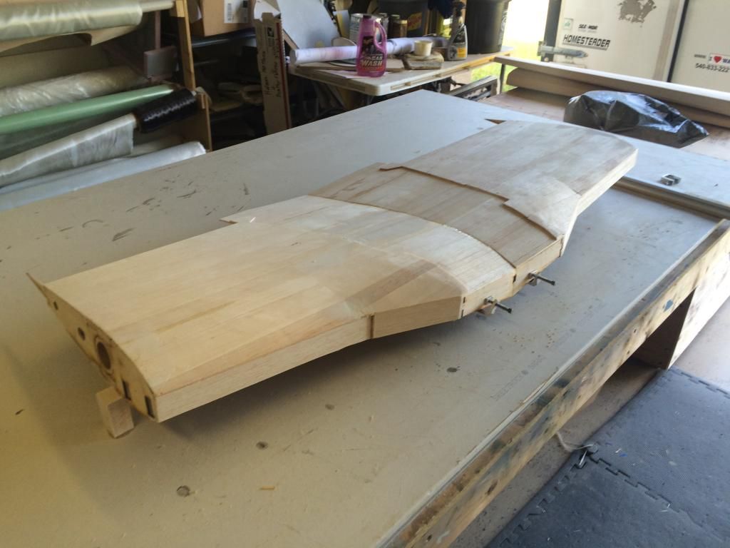
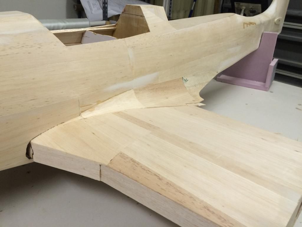
After getting the wing center section aligned, incidence set and the saddle all set, the ply wing fillet base was put in place. Then the F6/7 fillet bulkheads installed and the balsa sheet fillet glued in.
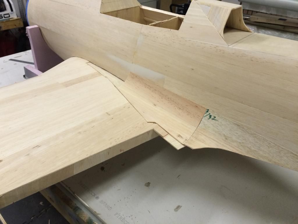
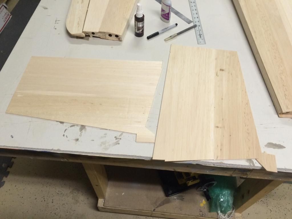
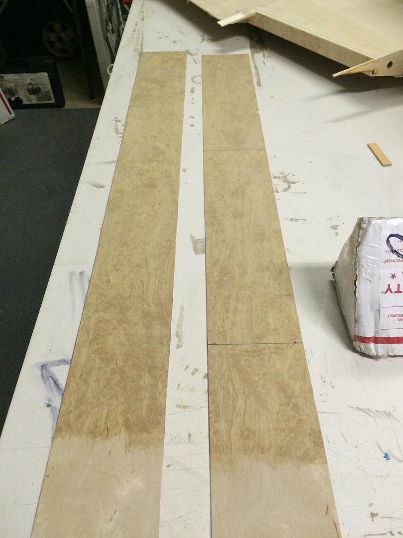
The fore fillets were then cut from a big block of balsa:
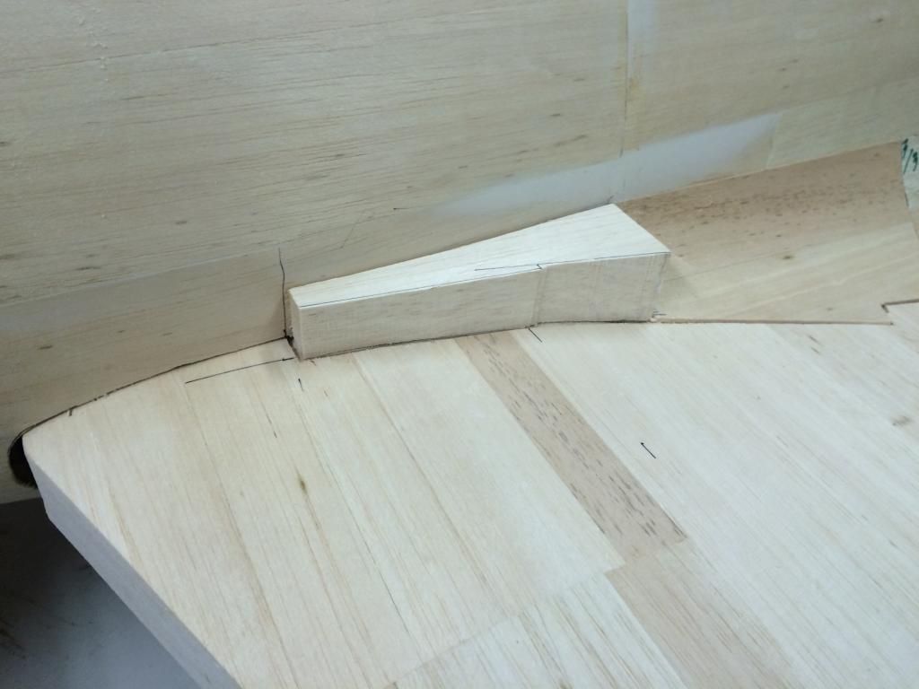
Then the slightly smaller blocks were shaved and sanded into even smaller parts to resemble a fillet. The plans show the outlines of these as a rectangular outline part along the top, but in reality, these have a curve to them as the Le of the fillet is extremely small and gradually builds up to the fillet shape so it follows a curve.
 12-25-2014, 06:40 PM
#150
Last night i glassed one side of some 1/64" ply for the inside surface of the wing skins over the flap.
Then the skins were cut out.
Then the structural ribs inside the flap well were drawn in CAD and the first were started out being 3D printed. I have to finish sheeting the bottom of the center wing section and apply some .003" G10 to the rear spar before i can glue all this stuff in.

Then the skins were cut out.

Then the structural ribs inside the flap well were drawn in CAD and the first were started out being 3D printed. I have to finish sheeting the bottom of the center wing section and apply some .003" G10 to the rear spar before i can glue all this stuff in.
