


Sopwith Scout "Pup" 1/4 scale Balsa USA
 12-11-2014, 07:55 PM
#26

Thread Starter

Join Date: Feb 2007
Location: Los Gatos, CA
Posts: 797
Likes: 0
Received 0 Likes
on
0 Posts
Finally with all the rib stitching complete time to paint the roundels on the bottom. The yellow masking (in photo 1) is made from my vinyl cutter. This comes in handy so much. The only draw back is that the vinyl is so sticky and can pull up any paint under it.
Using the vinyl as paint masks I first dull down the sticky ness by first applying the vinyl to my pants/jeans. I do the several time and sometimes the vinyl will still peal up the covered paint.
Go slow and carful and you can really get fantastic results.


Using the vinyl as paint masks I first dull down the sticky ness by first applying the vinyl to my pants/jeans. I do the several time and sometimes the vinyl will still peal up the covered paint.
Go slow and carful and you can really get fantastic results.

 12-13-2014, 11:06 AM
#30
Thread Starter
Join Date: Feb 2007
Location: Los Gatos, CA
Posts: 797
Likes: 0
Received 0 Likes
on
0 Posts
As the paint from the roundels are drying I’m going to work on the landing gear. I really don’t like having the rear two struts connect to the underside of the lower wing. This requires me to remove the landing gear each time I want to remove the lower wing for transport to the flying field.
My research educated myself to the fact that the full scale originally had a two piece lower wing and the chamfer to the underside allowed mounts to the fuselage without the lower wings interfering. On the Balsa USA this is not the case. This lower wing is one section only.
I plan on leaving the design as is and simply strengthen the struts and lower brace, along with making the axel to �”.
I built the landing gear per the plan and then I start to modify.
I started measuring the length of each strut and cutting aluminum streamline struts. Then I cut off the “L” shaped axels and the ends where the wire struts connected. This allowed me to slip the streamline struts over the wire struts.
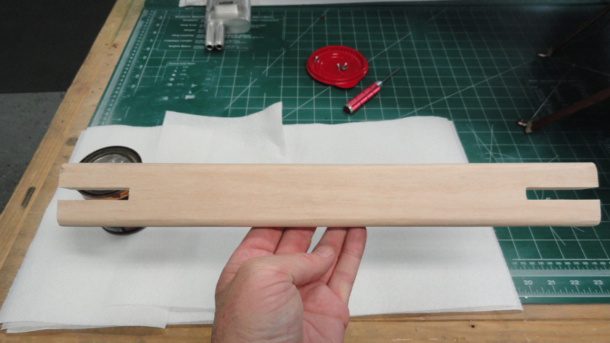
Using a solid piece of wood and my table saw I measured and cut the center wood section. Down the middle I cut a slot for the axel. The full scale has the axel running the length on top.
I gave this much thought as my other planes that are scale and use bungies are always in need of repair. I decided to go super strong and place the axel to the bottom.
I then drilled and tapped 6-32 holes at each end. Using my vice I crimped the ends of each aluminum strut. See Photo 5.
On the top I cut out groves into the ends to look more scale and also let the axel have some flex. The ends of the axels I have slipped on a washer and a brass sleeve. At the ends I drilled a hole so once the wheel is installed another washer and then a cotter pin added to secure the wheel.
To secure the axel I cut out sections to the bottom. Using an aluminum bar I cut pieces and drilled holes at each end. Using wood screws to capture the axel. I believe I’ll small grooves into the axel at these points so as to lock the axel into place and assist in side loading. See Photo 9.
Later I’ll add the brace wires.


My research educated myself to the fact that the full scale originally had a two piece lower wing and the chamfer to the underside allowed mounts to the fuselage without the lower wings interfering. On the Balsa USA this is not the case. This lower wing is one section only.
I plan on leaving the design as is and simply strengthen the struts and lower brace, along with making the axel to �”.
I built the landing gear per the plan and then I start to modify.
I started measuring the length of each strut and cutting aluminum streamline struts. Then I cut off the “L” shaped axels and the ends where the wire struts connected. This allowed me to slip the streamline struts over the wire struts.
Using a solid piece of wood and my table saw I measured and cut the center wood section. Down the middle I cut a slot for the axel. The full scale has the axel running the length on top.
I gave this much thought as my other planes that are scale and use bungies are always in need of repair. I decided to go super strong and place the axel to the bottom.
I then drilled and tapped 6-32 holes at each end. Using my vice I crimped the ends of each aluminum strut. See Photo 5.
On the top I cut out groves into the ends to look more scale and also let the axel have some flex. The ends of the axels I have slipped on a washer and a brass sleeve. At the ends I drilled a hole so once the wheel is installed another washer and then a cotter pin added to secure the wheel.
To secure the axel I cut out sections to the bottom. Using an aluminum bar I cut pieces and drilled holes at each end. Using wood screws to capture the axel. I believe I’ll small grooves into the axel at these points so as to lock the axel into place and assist in side loading. See Photo 9.
Later I’ll add the brace wires.
12-13-2014, 11:07 AM
#31
Thread Starter
Join Date: Feb 2007
Location: Los Gatos, CA
Posts: 797
Likes: 0
Received 0 Likes
on
0 Posts
I now decided to work on the gun. I wanted it to be more scale and yet I don’t want it to break apart with the running engine. First I’ll work on the ammunition boxes. After measuring the entrance and exit of the ammunition at the gun I decided to make them the same size for connivence.
Using a circle template I drew out the sides onto a piece of plastic. See Photo 3,4 and 5.
Also I made the tops and bottoms.
Using Plastic Weld and almost all my patients I glued the pieces together. Then painted them silver.
After the ammunition boxes were complete I wanted to see if I could make a pilot guard with glass plate. So I simply dove in and made a wood template to start. See Photo 12 and 13.
Looking at scale drawings there is a cross bar directly in the middle of the guard. This must have been hard to see around. I made this bar from a piece of brass tube. See Photo 14.
12-13-2014, 11:08 AM
#32
Thread Starter
Join Date: Feb 2007
Location: Los Gatos, CA
Posts: 797
Likes: 0
Received 0 Likes
on
0 Posts
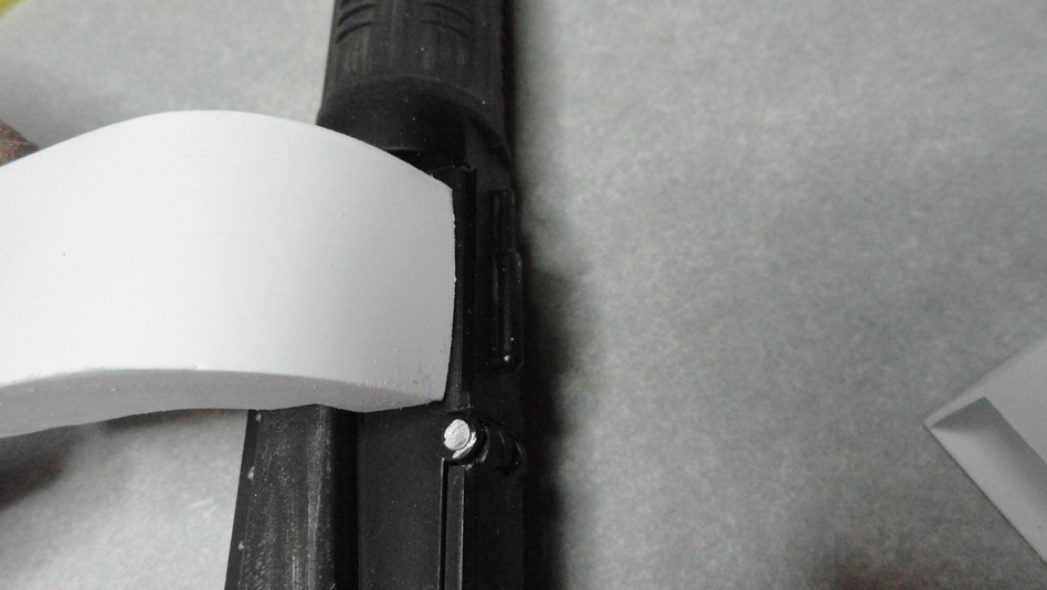
Having the guard and the cross bar the way I liked I now needed a way to attach it to the gun. Again looking at my scale drawings I could see how and why the cross bar was at that location. I started by making templates for the connection bars. See Photo 1 and 2.
I like the way they came out however, the attachment to the cross bar was very week. I knew that simply gluing it to the plastic would not hold. So using my Dremel tool I cut a slot into the brass tube (cross bar) int the rear. This allow the plastic to slip into the bar. This made the connection strong.
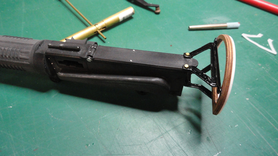
To connect the support bracing to the gun I glued and drilled holes and attached machine bolts.
I then added half round plastic rods to the face of the guard to give some volume when I applied the leather. I then painted the entire frame black and in photo 12 the face is resting in place.


I like the way they came out however, the attachment to the cross bar was very week. I knew that simply gluing it to the plastic would not hold. So using my Dremel tool I cut a slot into the brass tube (cross bar) int the rear. This allow the plastic to slip into the bar. This made the connection strong.
To connect the support bracing to the gun I glued and drilled holes and attached machine bolts.
I then added half round plastic rods to the face of the guard to give some volume when I applied the leather. I then painted the entire frame black and in photo 12 the face is resting in place.
12-13-2014, 11:10 AM
#33
Thread Starter
Join Date: Feb 2007
Location: Los Gatos, CA
Posts: 797
Likes: 0
Received 0 Likes
on
0 Posts
Taking real leather I drew and cut out a piece to cover the face of the guard. Using leather glue I glued the leather to the face. This glue is water soluble and dries clear. It soaks into the leather and stay in place. You need to continue to work into place as it dries. I was able to get the leather and glue at my local crafts store. I went to “Michael’s” craft store.
After the glued had dried, I trimmed the excess. At this point I wondered how I would attach a clear plastic piece to the rear and not have the cross bar in the way. Then it came to me. I’s simply make another wood frame and sandwich the clear plastic and that way then I attached the bar there would be enough space from the clear plastic. See Photos 7 - 14.


After the glued had dried, I trimmed the excess. At this point I wondered how I would attach a clear plastic piece to the rear and not have the cross bar in the way. Then it came to me. I’s simply make another wood frame and sandwich the clear plastic and that way then I attached the bar there would be enough space from the clear plastic. See Photos 7 - 14.
12-13-2014, 11:11 AM
#34
Thread Starter
Join Date: Feb 2007
Location: Los Gatos, CA
Posts: 797
Likes: 0
Received 0 Likes
on
0 Posts
At this point I became worries about the power system. I have already mounted my evaluation G-26 and it fits nicely. However, I have a Zenoha G-38 on the shelf. So I took off the 26 and mounted the 38.
Wow this was much larger than I thought. I would have to cut much more of the cowl so I took off the the G-38 and went back to my G-26. I’ll let you know when I fly how this works out.


Wow this was much larger than I thought. I would have to cut much more of the cowl so I took off the the G-38 and went back to my G-26. I’ll let you know when I fly how this works out.
12-13-2014, 11:12 AM
#36
Thread Starter
Join Date: Feb 2007
Location: Los Gatos, CA
Posts: 797
Likes: 0
Received 0 Likes
on
0 Posts
I found this on my old parts shelf and thought I might be fun to add some machine gun sounds. This is a RAMS kit 171 and it still works. I wonder if the sound will be loud enough. Where to install?

12-13-2014, 11:13 AM
#37
Thread Starter
Join Date: Feb 2007
Location: Los Gatos, CA
Posts: 797
Likes: 0
Received 0 Likes
on
0 Posts
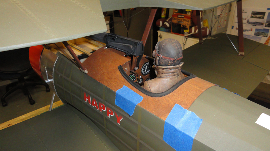
I wanted to stain and lacquer the wood deck around the pilot however I thought that the lacquer would not be as fuel proof as the epoxy paint of Klass Kote. So after letting the stain dry I painted a glossy clear coat of Klass Kote paint to the deck.

12-13-2014, 11:14 AM
#38
Thread Starter
Join Date: Feb 2007
Location: Los Gatos, CA
Posts: 797
Likes: 0
Received 0 Likes
on
0 Posts
While the deck is drying I thought I’d work on making some seat belts. Using light brown leather and leather glue, I cut strips of leather to make the belts. I used a square stock of wood with wood dowels at each end. The leather straps are glued to the dowels and the square stock is glued to the underside and the back of the seat.
The buckles are from Arizona Models. I had some left overs from my last kit.


The buckles are from Arizona Models. I had some left overs from my last kit.
12-13-2014, 06:10 PM
#41
Thank you for a very enjoyable read, just found your thread. Beautiful work, lots of scale detail. I built the QC Pup a few years ago, it is my favorite Sunday flyer. I have a very old Zenoah 23 in it and it is plenty of power for scale flight, with loops & rolls. I have the Zenoah 26 in the 100" SR Battery Eindecker, plenty power. I did add some scale details to the Pup but not as nice as yours. I took it to my third Dawn Patrol Rendezvous (09,11 & 14) sponsored by the USAF Museum In Dayton Ohio this year. I try to make all the dawn patrol & war bird events around Ok, Tx, Ar & Ks. I also take a BUSA QS Fokker D VII and soon a QS BUSA Spad XIII.
Sorry about hijacking your thread.
Here are a some picture.


I'll keep watching
Merry Christmas
Rich
Sorry about hijacking your thread.
Here are a some picture.
I'll keep watching
Merry Christmas
Rich
Last edited by jwrich; 12-13-2014 at 06:17 PM.
12-14-2014, 02:38 PM
#43
Thread Starter
Join Date: Feb 2007
Location: Los Gatos, CA
Posts: 797
Likes: 0
Received 0 Likes
on
0 Posts
The glue is Hysol. It's very strong. Also between the "L" bracket and the cowl, I have placed a rubber washer and an aluminum washer.
Do you think I should also drill and add some hardware through the firewall to secure it more?
Michael
12-14-2014, 02:44 PM
#44
Thread Starter
Join Date: Feb 2007
Location: Los Gatos, CA
Posts: 797
Likes: 0
Received 0 Likes
on
0 Posts
I'm happy to have you visit. Also super to hear about the use of a G-23. I want this bird to be a fun flyer and any given weekend. If the bird is under powered it will simply be a scale flyer. I want to be able to do rolls and full loops.
Thanks,
Michael
12-14-2014, 03:06 PM
#45
Thread Starter
Join Date: Feb 2007
Location: Los Gatos, CA
Posts: 797
Likes: 0
Received 0 Likes
on
0 Posts
Thank you for a very enjoyable read, just found your thread. Beautiful work, lots of scale detail. I built the QC Pup a few years ago, it is my favorite Sunday flyer. I have a very old Zenoah 23 in it and it is plenty of power for scale flight, with loops & rolls. I have the Zenoah 26 in the 100" SR Battery Eindecker, plenty power. I did add some scale details to the Pup but not as nice as yours. I took it to my third Dawn Patrol Rendezvous (09,11 & 14) sponsored by the USAF Museum In Dayton Ohio this year. I try to make all the dawn patrol & war bird events around Ok, Tx, Ar & Ks. I also take a BUSA QS Fokker D VII and soon a QS BUSA Spad XIII.
Sorry about hijacking your thread.
Here are a some picture.
I'll keep watching
Merry Christmas
Rich
Sorry about hijacking your thread.
Here are a some picture.
I'll keep watching
Merry Christmas
Rich
This is not hi-jacking my thread at all. I love all the photos of everyone's planes. Your planes are great! Does the Eindecker have wing wrapping controls?
Also happy to learn about your Pup running on a G-23. I too want this Pup for an every day flyer. Looking forward to starting her up for the first time in a week. I purchased a video camera and I'm starting to work it out for posting. My goal will be to make a video of my first start up if the Eveloution G-26.
Please let let me know about any and all Dawn Patrols as I want to take several trips this year.
Thanks,
Michael
12-14-2014, 03:55 PM
#46

My Feedback: (1)
Hysol is pretty strong, so I am not sure whether any further hardware is needed. Certainly a screw through each would guarantee that it doesn't come loose. Since it's up front where weight isn't an issue, I personally would add a screw in each.
-Ed B.
12-14-2014, 09:36 PM
#48
Thread Starter
Join Date: Feb 2007
Location: Los Gatos, CA
Posts: 797
Likes: 0
Received 0 Likes
on
0 Posts
Andy,
The Vickers machine gun is a plastic kit from Williams Brothers, However, the ammo bins and the front bumper are hand made. Also they make lots of other � scale guns, however, NO 1/3rd scale. Sorry.
Hysol is a 3M product that is really strong epoxy. It comes in these plastic barrels and that you snap into a squeeze handle and the tips mix the two part epoxy as you squeeze the handle. It's not all that cheep, however, very strong. It also comes in different drying times and strengths. The type I used for the cowl is stronger than JB Weld. It takes over night to harden and 24 hours to cure.
Ed,
OK I'll drill a hole and secure the "L" brackets, because I agree that it would be better and I'll have access just before I epoxy the firewall to fuel proof it.
Thanks
12-14-2014, 09:39 PM
#49
Thread Starter
Join Date: Feb 2007
Location: Los Gatos, CA
Posts: 797
Likes: 0
Received 0 Likes
on
0 Posts
I wanted to get the wood deck panel secured over the cockpit area so I needed to finish the inside padding for the pilot. At first I didn’t know how I was going to achieve the stitching. I had the rubber made for this (it already has a slit for installing) so I started with this. Looking at my documentation i found that the padding did not go all the way around the opening in the wood deck. I trimmed it as shown.
After some thought I went to my local crafts store ( Michael’s ) and found a package with an assortment of eyelets. They look like small grommets. The package has four different sizes and three metals. There is brass, aluminum and gold or at least the color of gold. I had to purchase two packages. See Photo 5 and 6.
Photo one is my test piece. Each time I do something new to me I want to test out the procedure on a test piece. Photo three shows the padding simply applied. No glue at this time.
Photo four show how I marked the spacing. I took a piece of wood and with a ruler made �” marks on one edge of the wood. Next using that piece of wood I mark the rubber padding and move the wood piece as a guide and mark the spacing all along the entire padding. See Photo 4.
After several attempts and errors, I found that simply drilling at each of my marks and inserting a single eyelet gave me the correct look I was going after. Still no glue at all. See Photos 7,8 and 9.
After all the eyelets have been inserted I added the thread or rope. I went in and out of every other eyelet and then went back the same way. This gave the full stitched look.
What do you think? Should I have only stitched half as seen in photo 11? Or see photo 12 for a side by side to judge. I went with the full, however, I can always remove the one half. This would be easy to do.
Last edited by MRadu; 12-15-2014 at 11:54 AM.
12-15-2014, 07:24 AM
#50
Michael,
The double stitching seems to be the most correct although some do have single stitching but it just might be the restoration process. The original used padded leather around the cockpit opening. I have hundreds of pictures and I have scale documentation I've posted a few of the relevant ones.


Andy
The double stitching seems to be the most correct although some do have single stitching but it just might be the restoration process. The original used padded leather around the cockpit opening. I have hundreds of pictures and I have scale documentation I've posted a few of the relevant ones.
Andy