


Sopwith Scout "Pup" 1/4 scale Balsa USA
 12-15-2014, 07:35 AM
#51

Andy,
The Vickers machine gun is a plastic kit from Williams Brothers, However, the ammo bins and the front bumper are hand made. Also they make lots of other Ľ scale guns, however, NO 1/3rd scale. Sorry.
Hysol is a 3M product that is really strong epoxy. It comes in these plastic barrels and that you snap into a squeeze handle and the tips mix the two part epoxy as you squeeze the handle. It's not all that cheep, however, very strong. It also comes in different drying times and strengths. The type I used for the cowl is stronger than JB Weld. It takes over night to harden and 24 hours to cure.
Thanks
I am trying to figure out how to create the louvers for a 1/3 scale Vickers my pup. Alex from Iflytailies is working on a 1/3 scale Vickers machine gun that he is going to 3D print. I may buy that and use the barrel portion. I am thinking about building the back of the gun out of aluminum and making all of the levers out of it as well.
Another thing you can do is add an LED to the barrel of the machine gun so that when you activate your sound system you can have the gun look like its firing. I'm doing that on my 1/4 scale BUSA SE5A I'll have one in the Vickers gun and one in the Lewis machine gun. They don't have to synchronize with the sound because you would see the flash before you heard the sound any way.
I have a sound system for my SE5A and a buddy of mine is trying to convince me to put in an amplifier to make the sound louder. I am still thinking about that.
Andy

 12-15-2014, 11:17 AM
#53

Thread Starter

Join Date: Feb 2007
Location: Los Gatos, CA
Posts: 797
Likes: 0
Received 0 Likes
on
0 Posts
Wow!
Thanks Andy
Those photos are great to have for reference. It shows all my errors and my guess work. I used to much thread count in my strapping the cockpit opening. Also my gun bays are fully enclosed on the intake side. Another error. My shape to the front bumper is also incorrect. Another error. My seat belts are also in error.
Now I know about the saying "ignorance is bliss."
Oh well I'm having fun and this will be my everyday fun flyer.
Thanks Andy for sharing. Please send more photos of the Pup. I do like to see how scale I can get and with each build I get better.
I'm already thinking about finishing my framed up Balsa USA Ľ scale SE5a next. Or my ⅓ scale Fokker D.VII all framed as well.
Do you have any photos of a SE5a?
I have a ⅓ scale Fokker D.VII already framed and a ⅓ scale SE5a in box from Glenn Torrence and these I want to scale out to the max.
I have already started the Fokker and it's framed with gear complete. I have a G-62 with a gear reduction system to swing a scale prop.
I found a guy selling ⅓ scale guns that he makes from his 3D printer. I'm also looking into the printer as I know the costs are coming down.
If you want I'll dig up his web site and you can see if his gun is good for your ⅓ Pup, or do you have that already. Also if you want I'll send photos of his product as they came to me.
Let me know and thanks again for the photos. They show me I can do MUCH better on my builds.
Michael
12-15-2014, 11:26 AM
#54
Thread Starter
Join Date: Feb 2007
Location: Los Gatos, CA
Posts: 797
Likes: 0
Received 0 Likes
on
0 Posts
Rich,
You can get the rubber combing from Proctor Enterprise. He has almost every scale item for WWI planes! Just not so much stuff for ⅓ scale. Most is Ľ scale. Great guy and really knows about WWI aircraft.
I.M.P.
Michael
12-15-2014, 11:40 AM
#55
Thread Starter
Join Date: Feb 2007
Location: Los Gatos, CA
Posts: 797
Likes: 0
Received 0 Likes
on
0 Posts
Andy,
I think and I know for myself I'd have the gun 3D printed, simply because of those louvers! That's just me. I would love to learn how you do it if you pull it off!
As for the light in the barrel of the gun, I'd like that very much, however, I don't know how to make the light flash / blink. I have added lights to my other planes and found that at Electric Dynamics they make and sell light super bright, however, the only flashing light they make is a beacon and it blinks to slow to be a gun flash.
How do you make your lights flash?
I too am working on making my sound louder. The RAM system states I can strap two 9volt batteries together and make a bigger box and or add a second speaker. Still testing this out.

On the top servo I simply rubber glued the switch to the servo for activating the sound.

Here is where I'm thinking about adding the speaker. There is room for two?
Anyone have some ideas?
I think and I know for myself I'd have the gun 3D printed, simply because of those louvers! That's just me. I would love to learn how you do it if you pull it off!
As for the light in the barrel of the gun, I'd like that very much, however, I don't know how to make the light flash / blink. I have added lights to my other planes and found that at Electric Dynamics they make and sell light super bright, however, the only flashing light they make is a beacon and it blinks to slow to be a gun flash.
How do you make your lights flash?
I too am working on making my sound louder. The RAM system states I can strap two 9volt batteries together and make a bigger box and or add a second speaker. Still testing this out.
On the top servo I simply rubber glued the switch to the servo for activating the sound.
Here is where I'm thinking about adding the speaker. There is room for two?
Anyone have some ideas?
12-15-2014, 04:20 PM
#56

Join Date: May 2013
Location: Orillia, ON, CANADA
Posts: 34
Likes: 0
Received 0 Likes
on
0 Posts
Hi Michael, this is what i am using on my Fokker and managed to get the leds in the spandue guns using alumium tube as a barrel. The leds plug into the sound board and flash with the sound. The sound board can be programed off of your radio with a spare channel..
I don't know if you will be able to hear it in the air but it will be a hit for static display.
http://www.hobbyking.com/hobbyking/s...dproduct=38890
http://www.hobbyking.com/hobbyking/s...dproduct=38003
I don't know if you will be able to hear it in the air but it will be a hit for static display.
http://www.hobbyking.com/hobbyking/s...dproduct=38890
http://www.hobbyking.com/hobbyking/s...dproduct=38003
12-15-2014, 05:04 PM
#57
Thread Starter
Join Date: Feb 2007
Location: Los Gatos, CA
Posts: 797
Likes: 0
Received 0 Likes
on
0 Posts
Hi Michael, this is what i am using on my Fokker and managed to get the leds in the spandue guns using alumium tube as a barrel. The leds plug into the sound board and flash with the sound. The sound board can be programed off of your radio with a spare channel..
I don't know if you will be able to hear it in the air but it will be a hit for static display.
http://www.hobbyking.com/hobbyking/s...dproduct=38890
http://www.hobbyking.com/hobbyking/s...dproduct=38003
I don't know if you will be able to hear it in the air but it will be a hit for static display.
http://www.hobbyking.com/hobbyking/s...dproduct=38890
http://www.hobbyking.com/hobbyking/s...dproduct=38003
Thanks Paul,
I like this. I have the sound and want to add lights. Do you have these? If so are the lights bright enough to see in direct sunlight?
Michael
12-15-2014, 05:12 PM
#58
Join Date: May 2013
Location: Orillia, ON, CANADA
Posts: 34
Likes: 0
Received 0 Likes
on
0 Posts
Yes they are too bright. So i took some black paint and just wiped it over them to get a more realastic look. I fit them back in the blast nozzels. I used a y harness to hook them to the sound board.
Hope this helps.
Hope this helps.
12-15-2014, 09:46 PM
#59
Andy,
I think and I know for myself I'd have the gun 3D printed, simply because of those louvers! That's just me. I would love to learn how you do it if you pull it off!
As for the light in the barrel of the gun, I'd like that very much, however, I don't know how to make the light flash / blink. I have added lights to my other planes and found that at Electric Dynamics they make and sell light super bright, however, the only flashing light they make is a beacon and it blinks to slow to be a gun flash.
How do you make your lights flash?
I too am working on making my sound louder. The RAM system states I can strap two 9volt batteries together and make a bigger box and or add a second speaker. Still testing this out.
On the top servo I simply rubber glued the switch to the servo for activating the sound.
Here is where I'm thinking about adding the speaker. There is room for two?
Anyone have some ideas?
I had this guy that I met at Toledo make up a special setup for my SE5A. ([email protected]) He had a booth at Toledo Weak Signals show and he custom built a board for me that has two distinct flash patters. For the Vickers gun that fires through the prop it does a 3-flash then pauses and then repeats to simulate firing through the prop. The Lewis gun just flashes quickly to simulate the unrestricted firing of the Lewis gun.
I have his phone number and his contact info down stairs in the basement with the board that he built for me. He makes LEDs for Mustangs and other war birds.
As far as the speaker is concerned, I went with the 4" speaker from Ram and I am mounting it in the bottom of the Fuse as far forward as I can mount it. I figure it is better to have it pointing at the ground.
Andy
12-19-2014, 09:35 AM
#60
Thread Starter
Join Date: Feb 2007
Location: Los Gatos, CA
Posts: 797
Likes: 0
Received 0 Likes
on
0 Posts
Andy,
Thanks for the info I'll try to get in touch with him and let you how it goes.
I'm going to take you advice and locate the speaker on the bottom.
Thanks
Thanks for the info I'll try to get in touch with him and let you how it goes.
I'm going to take you advice and locate the speaker on the bottom.
Thanks
12-19-2014, 09:37 AM
#61
Thread Starter
Join Date: Feb 2007
Location: Los Gatos, CA
Posts: 797
Likes: 0
Received 0 Likes
on
0 Posts
In photos one and two I have drilled and inserted a solid steal rod and using Hysol epoxy into the struts at the lower end.
After the glue had dried for more than 24 hours I painted them dark grey. I also painter the the axle and it’s mounting brackets flat black.
Before I can secure the top front panel I think I should add some weight. Not sure how much however this is a great place to add weight. I wish I could place the batteries here, however, I’d never be able to get them out if they were to fail. So for now I’ll mix up some twelve minute epoxy with some steal powder (this add extra weight to the glue). I also added two pieces of lead weight and used the epoxy to secure them.


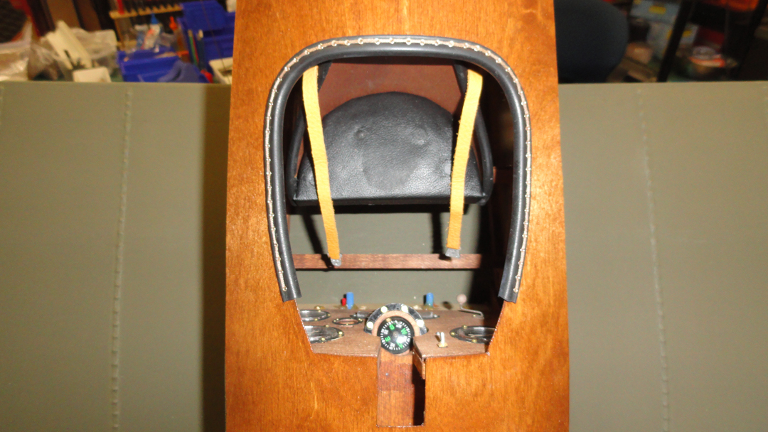


I like this photo (#7) You can just barely make out the pilots eye. Just ready to shoot you down!
After the glue had dried for more than 24 hours I painted them dark grey. I also painter the the axle and it’s mounting brackets flat black.
Before I can secure the top front panel I think I should add some weight. Not sure how much however this is a great place to add weight. I wish I could place the batteries here, however, I’d never be able to get them out if they were to fail. So for now I’ll mix up some twelve minute epoxy with some steal powder (this add extra weight to the glue). I also added two pieces of lead weight and used the epoxy to secure them.
I like this photo (#7) You can just barely make out the pilots eye. Just ready to shoot you down!
Last edited by MRadu; 12-19-2014 at 09:47 AM.
12-19-2014, 09:39 AM
#62
Thread Starter
Join Date: Feb 2007
Location: Los Gatos, CA
Posts: 797
Likes: 0
Received 0 Likes
on
0 Posts
Once the glue had become sticky and almost dry, I went to work on the front top panel.
In photos one through four I continually sanded a little and then placed back to see alinement. I did this a lot and in two places I took off more than I wanted.
Now with the panel cut to it’s final shape I brought out the aluminum tape for ducts.
I made sure the work surface and all things around were super clean. Then I did the same to the panel. As any tiny of anything will show up if trapped under the aluminum.
I cut a piece of aluminum a little larger so as to have some extra to wrap around the edges.
Using a plastic Bondo wiper edge I smooth out the aluminum over the panel. I also use a roller to make sure the aluminum is secured to the panel.
Trim all around the edges. See Photo 9. Using only my hands I fold and rub the aluminum to all edges. At the corners I cut out the over lapping edges.
I used 15 minute epoxy and blue tape to secure the panel to the top of the fuselage and wait to dry.
12-19-2014, 09:43 AM
#63
Thread Starter
Join Date: Feb 2007
Location: Los Gatos, CA
Posts: 797
Likes: 0
Received 0 Likes
on
0 Posts
In photo one you can see one of many of my dividers of all my tiny bolts and rivets. I pull out several pinches of rivets.
Using my Great Planes plastic template and a sharpie I mark the location of rivets. See Photo 2.
Then using my Dremel tool with a small drill bit I drill each mark.
Taking my needle knows pliers I grip a single rivet and dip each one into a small tin pan with CA and wet the tip of the rivet. Then I place each one into a previously drilled hole. I tap the rivet into it’s final position with the back end of my screw driver.
Some CA may stream out around the edges. So for this I add some CA remover to a piece of paper towel and wipe the heads to clear and excess CA.
12-23-2014, 08:20 AM
#66
Thread Starter
Join Date: Feb 2007
Location: Los Gatos, CA
Posts: 797
Likes: 0
Received 0 Likes
on
0 Posts
I was planning on just having a simple dummy engine and was not going to add any detail. Well that changed quickly when I dry fitted it into the cowl. I saw far to much space between the fake cylinders.
So I thought I’d add the brass or copper exhaust pipes. Just how I was not sure. I started with a test piece of brass and placed it into the vice. I liked how it came out, however, how to get all seven the same? I came up with the idea a placing some plywood spacers in the vice so while squeezing the brass tubes the plywood spacers stop the pressure at the same place.
I’m happy with the outcome, however, if I wanted them more scale it might have been better to carve out two halves in hard wood and squeeze the brass tubes to the desired shape.
Using the belt sander I shaped the ends that are closer to the center, as the other ends are not seen I’ll epoxy them to the outer ring.
In photo 8 you can see that for one of the exhaust pipes I tried to drill a hole in the engine and found that this was not going to work. I’ll have to fill in this area and paint.
Then at that point I had the idea of coloring the pipes, however, I did not want to paint each one. I used some pliers to hold one end of the pipe and at the other I used my blow torch only at the end and heated until the end glowed orange red. See Photos 9 through 11.
I’ll do some more touch up and clean up to finish up the engine before I secure it to the cowl.
What do you think about adding some backing to block the air flow between cylinders that are not at the engine?
12-23-2014, 08:22 AM
#67
Thread Starter
Join Date: Feb 2007
Location: Los Gatos, CA
Posts: 797
Likes: 0
Received 0 Likes
on
0 Posts
As the epoxy is drying on the exhaust I want to work out the detail of the making the brace wires. I started with the brace wires over the top of the fuselage just aft of the cowl.
In photo 1 the turnbuckles with slotted ends are from Proctor Enterprises. The brass connector is to small to attach the wing struts. So I started to make my own. See Photos 3 through 8. I found these connection to be to large and they forced the wing strut to not sit flush to the fuselage.
I took some smaller brass strips and realized that these wires are not structural and therefore do not have to be supper strong.
I took the brass strip and bent it into an angled “L” shape. Then I cut a slot into the top of the fuselage. I found this helpful as it also allowed me to raise the turnbuckle up to be able to fit the bolt and nut.
12-23-2014, 08:23 AM
#68
Thread Starter
Join Date: Feb 2007
Location: Los Gatos, CA
Posts: 797
Likes: 0
Received 0 Likes
on
0 Posts
Now with the turnbuckles secure, I decided to silver solder the brass connections to the wing mounts. In photo one the hole for the wing bolt is reduced by the brass connection. After the solder had cooled I drilled out the hole to it’s original size.
Finally I used blue lock tight to lock the turnbuckles.


Finally I used blue lock tight to lock the turnbuckles.
12-24-2014, 09:30 AM
#73
Merry Christmas Michael!
I love the details. One thing you can do with your turnbuckles that they did on the full size plane is to wrap a thin wire around each end of the turnbuckle and through the hole in the middle. They did this to keep the turnbuckles from unscrewing. It is a small detail but it does add that additional level of realism to it.
Andy
 12-27-2014, 11:02 PM
#75
Thread Starter
Join Date: Feb 2007
Location: Los Gatos, CA
Posts: 797
Likes: 0
Received 0 Likes
on
0 Posts
Thank to all who posted. Glad you are still watching.
It’s time to fuel proof the fire wall with epoxy. I used 20 minute epoxy and added a small amount of denatured alcohol to thin out the epoxy. It makes it thin and you can spread it a long way. When you do this thinning, the epoxy takes much longer to dry. It stayed sticky to the touch for about two hours. It was cold in the garage which adds more drying time as well.
I did not take a photo of the epoxy on the fire wall, however, I did show that I added screws to the “L” brackets for the cowl. See Photo 2.
Starting with photo 3 I’m beginning to place all the items needed. In photo 3 the fuel tank is installed and both switches with charging jacks.
I was fitting all the items and did not take photos of each time I installed one. So look at photos 4 through 7. I have installed the following items in the front bay.
In photos 8 through 14 I first used some tracing paper the create the size of the bottom panel. The tracing paper allowed myself to see through and mark the location on the speaker and the mounts for the landing gear bar.
The last two photos show that once I had completed the bottom panel I covered it with aluminum tape.


It’s time to fuel proof the fire wall with epoxy. I used 20 minute epoxy and added a small amount of denatured alcohol to thin out the epoxy. It makes it thin and you can spread it a long way. When you do this thinning, the epoxy takes much longer to dry. It stayed sticky to the touch for about two hours. It was cold in the garage which adds more drying time as well.
I did not take a photo of the epoxy on the fire wall, however, I did show that I added screws to the “L” brackets for the cowl. See Photo 2.
Starting with photo 3 I’m beginning to place all the items needed. In photo 3 the fuel tank is installed and both switches with charging jacks.
I was fitting all the items and did not take photos of each time I installed one. So look at photos 4 through 7. I have installed the following items in the front bay.
- (2) Switches with charging jacks.
- A LiPo 2 Cell 7.4 volt battery for ignition.
- (2) 9 volt batteries that I soldered together to make an 18 volt battery that is connected to:
- An on/off switch.
- A 6 volt 4500 mAh battery
- The chip board of the sound system.
- The 2” inch speaker.
- The fuel vent / over fill tube.
- The fuel fill cap.
In photos 8 through 14 I first used some tracing paper the create the size of the bottom panel. The tracing paper allowed myself to see through and mark the location on the speaker and the mounts for the landing gear bar.
The last two photos show that once I had completed the bottom panel I covered it with aluminum tape.