


Ziroli 92" p-47 build thread

 07-18-2019, 02:20 PM
#178
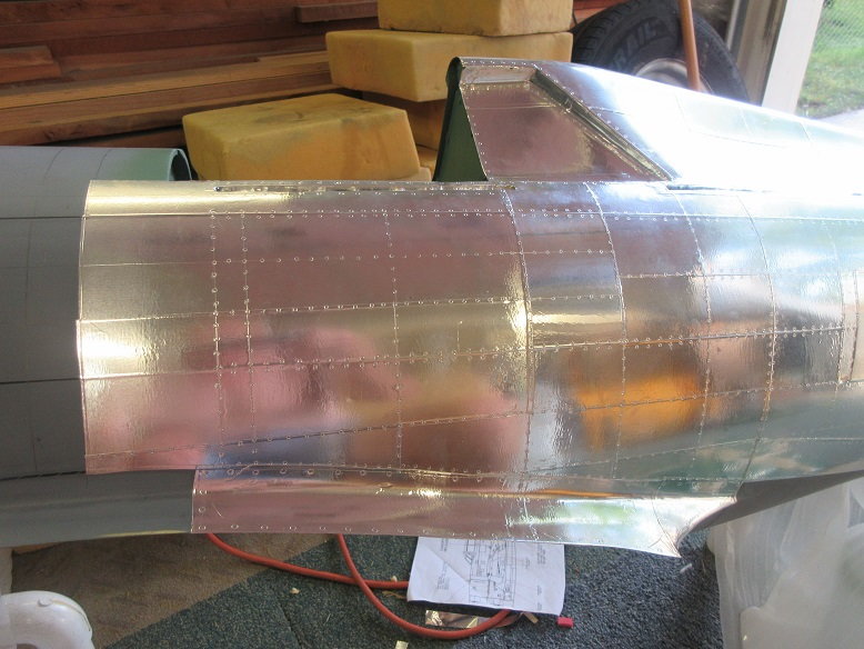
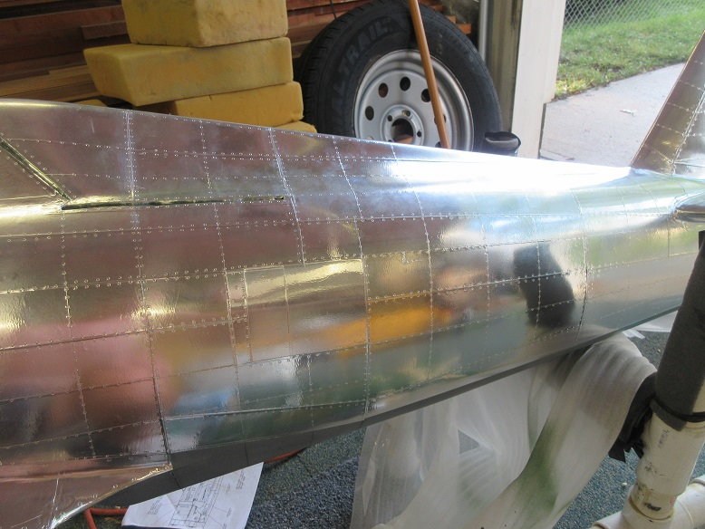
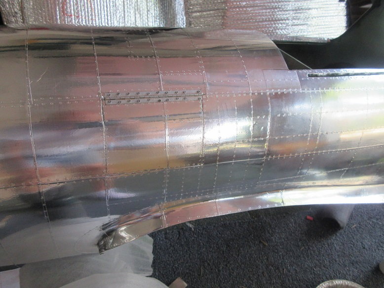
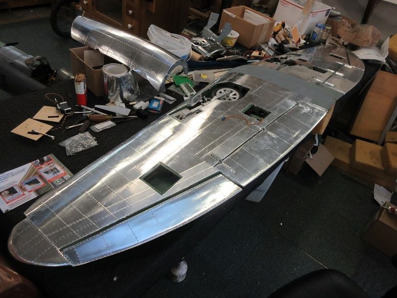
Aluminum application (cont)
Bottom of fuse done.
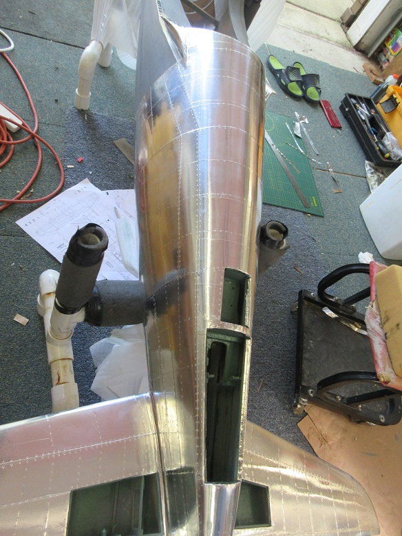
Most of right side of fuse done.
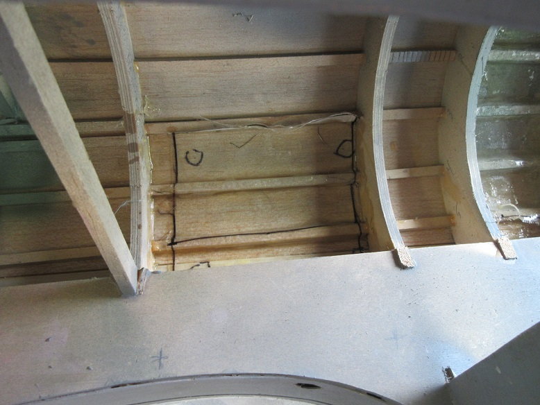
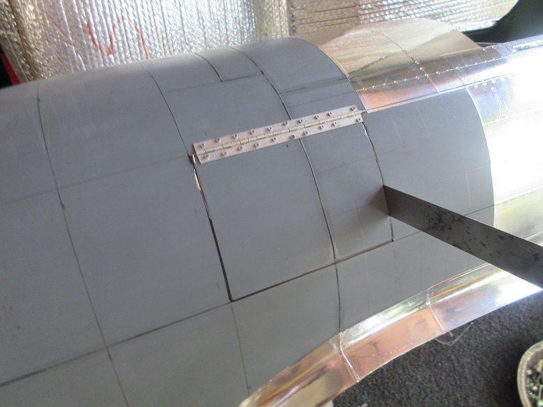
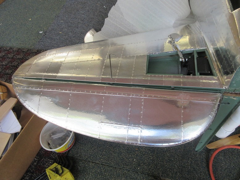
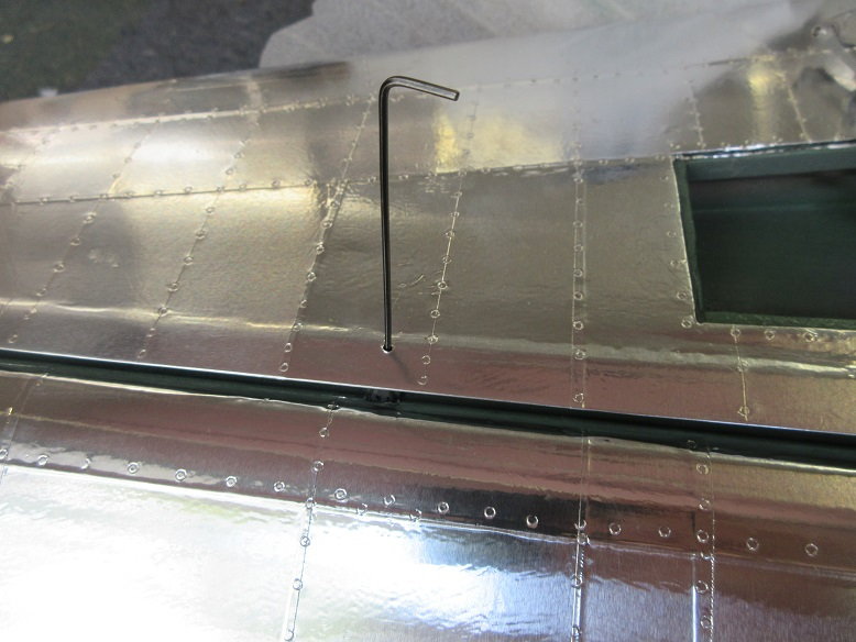
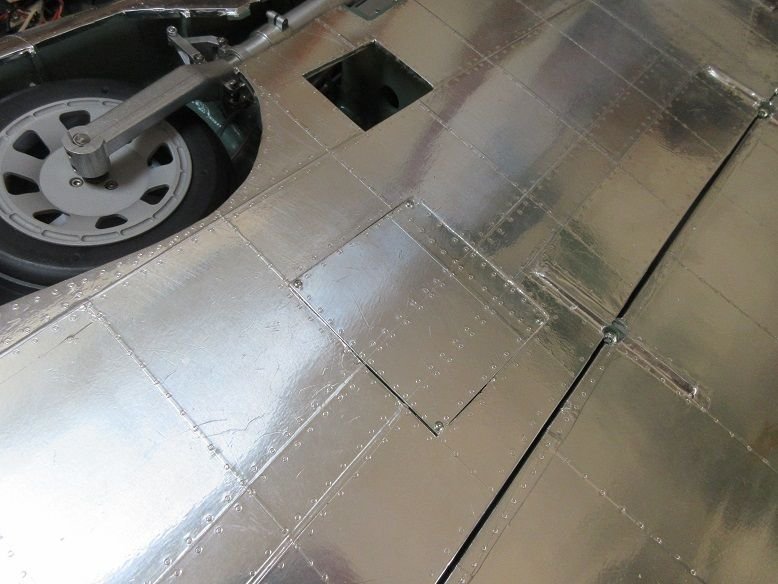
Decided to make my usual 3"X4" access panel hatch on the left side of the fuse.
Stuck pins in fuse to locate proper position of hatch so not to interfere with formers.
Able to locate door edges along rivet lines.
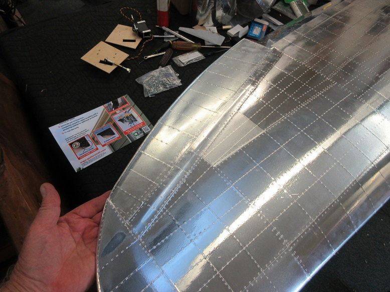
Laid up some 2 oz FG cloth to reinforce the door area and insure the door keeps its original shape.
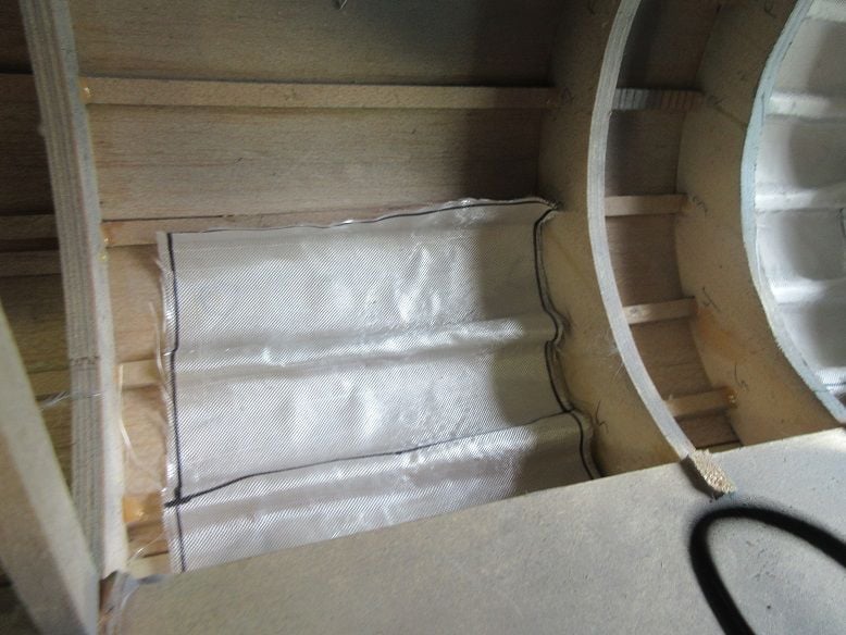
Also, finished laying up FG cloth in the top half of the fuse by the fire wall.
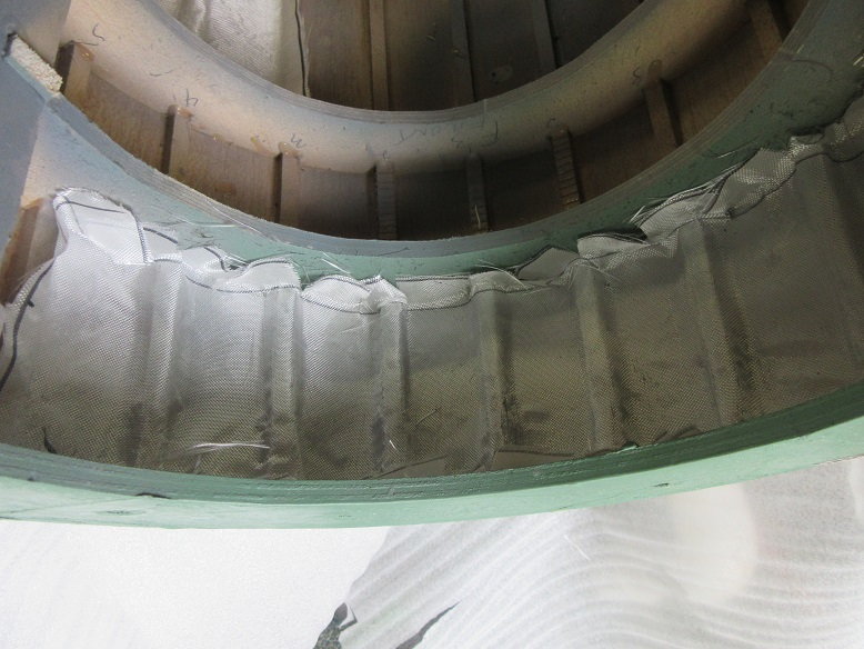
Zap finishing resin added: let that cook overnight.
Black circles are corners of door.
Bottom of fuse done.
Most of right side of fuse done.
Decided to make my usual 3"X4" access panel hatch on the left side of the fuse.
Stuck pins in fuse to locate proper position of hatch so not to interfere with formers.
Able to locate door edges along rivet lines.
Laid up some 2 oz FG cloth to reinforce the door area and insure the door keeps its original shape.
Also, finished laying up FG cloth in the top half of the fuse by the fire wall.
Zap finishing resin added: let that cook overnight.
Black circles are corners of door.
Last edited by samparfitt; 07-18-2019 at 02:27 PM.
07-24-2019, 10:38 AM
#179
Able to get back to planes after working on son's and daughter's cars and house duties.
============
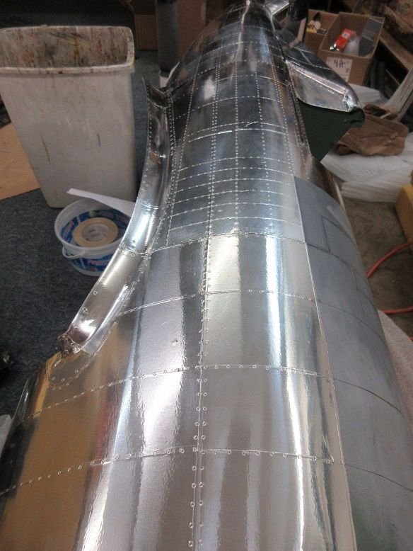
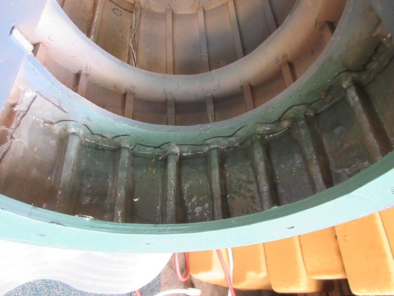
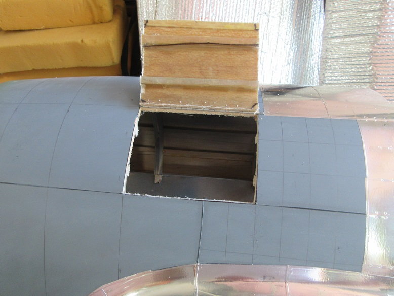
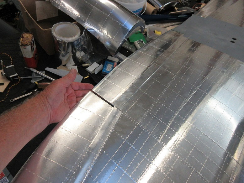
Service panel door.
Used some piano hinge for the door.
Cut the top of door and installed the hinge and, then, cut the remaining three sides with a razor saw with no backing.
Previously applied FG cloth and resin kept the door's shape.
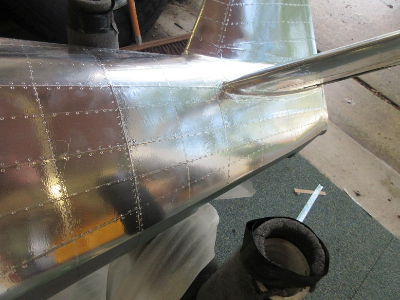
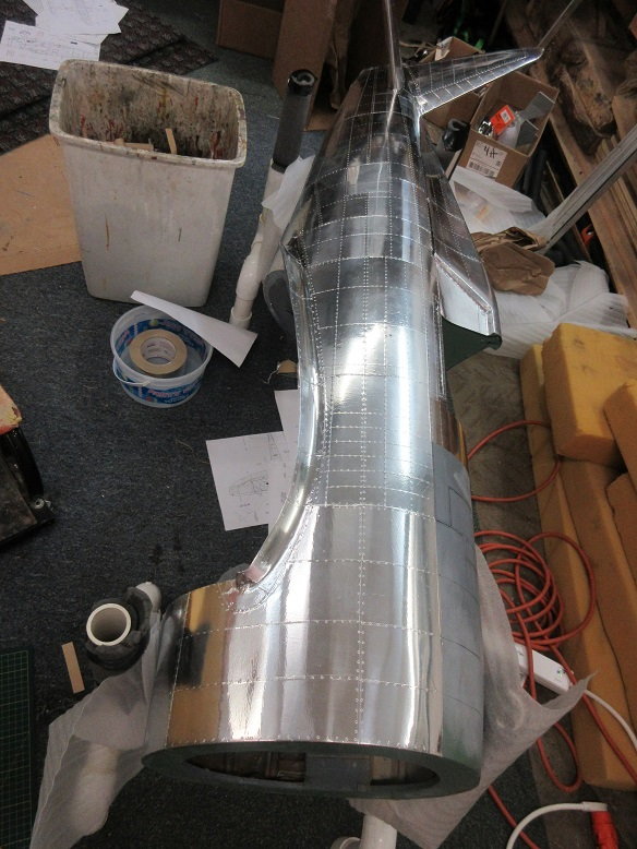
Aluminum application (cont)
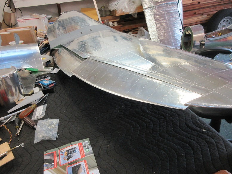
Fuse done.
Service panel door.

============
Service panel door.
Used some piano hinge for the door.
Cut the top of door and installed the hinge and, then, cut the remaining three sides with a razor saw with no backing.
Previously applied FG cloth and resin kept the door's shape.
Aluminum application (cont)
Fuse done.
Service panel door.
Last edited by samparfitt; 07-24-2019 at 03:35 PM.
 07-26-2019, 03:54 PM
#182
Thanks, Bob,
==========
Had to power clean the deck and bench and apply water sealant; now back to planes.
TF kit F6F: replaced the loud muffler with a Zenoah stock muffler on the G-62 and get ready for Saturday's club picnic.
============
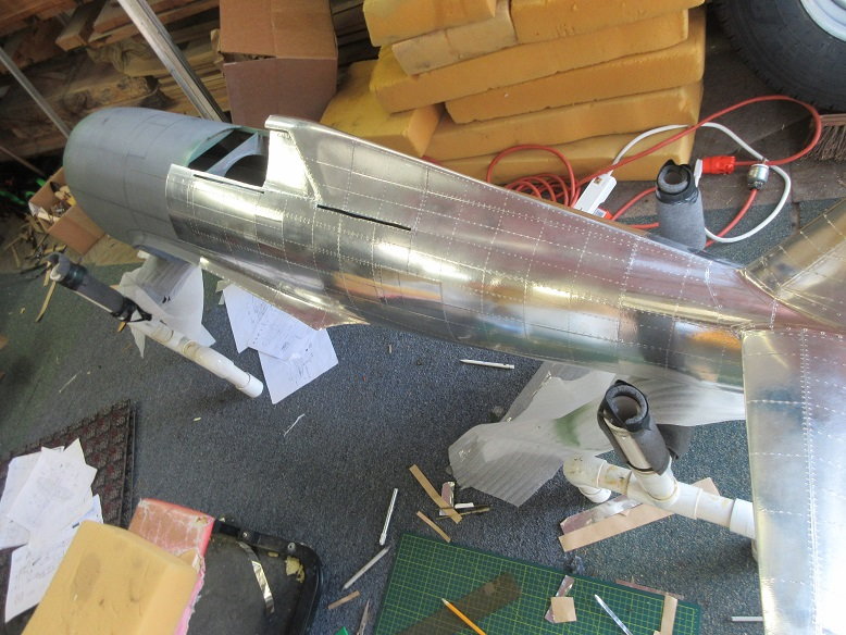
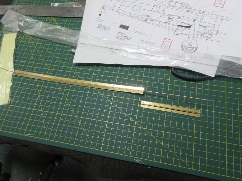
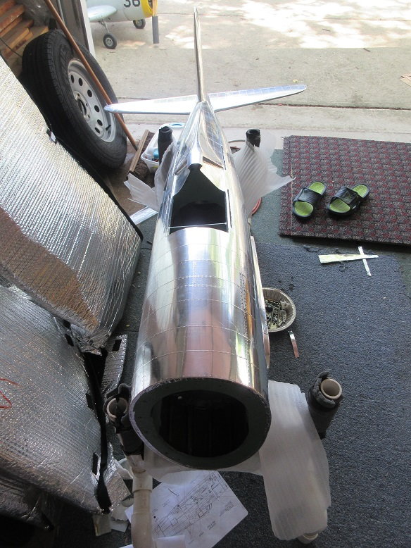
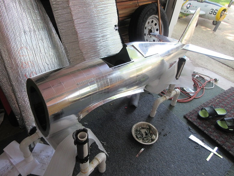
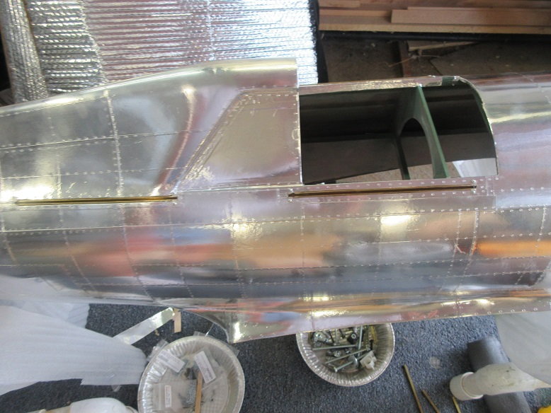
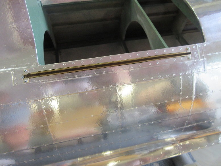
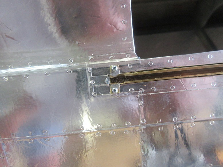
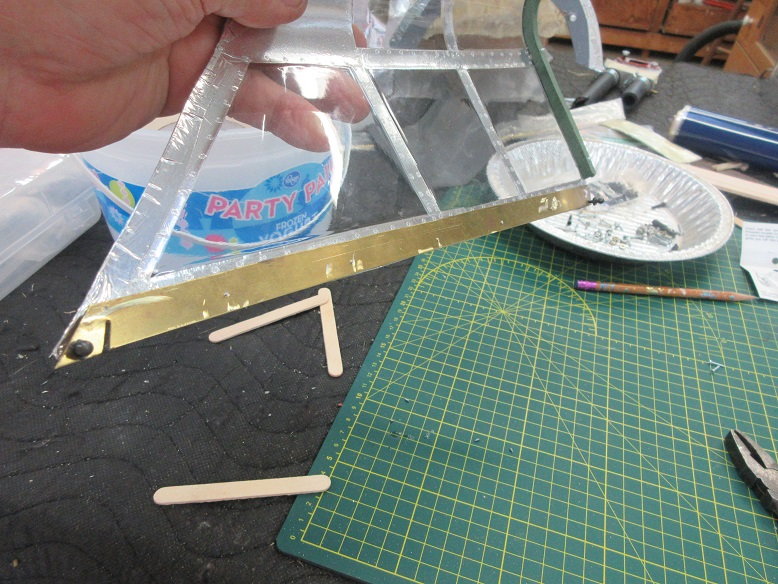
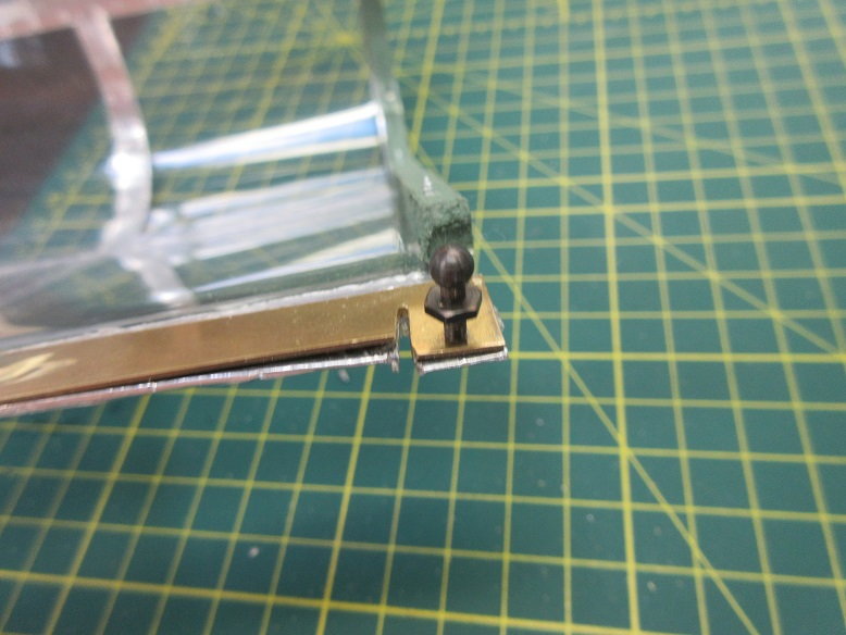
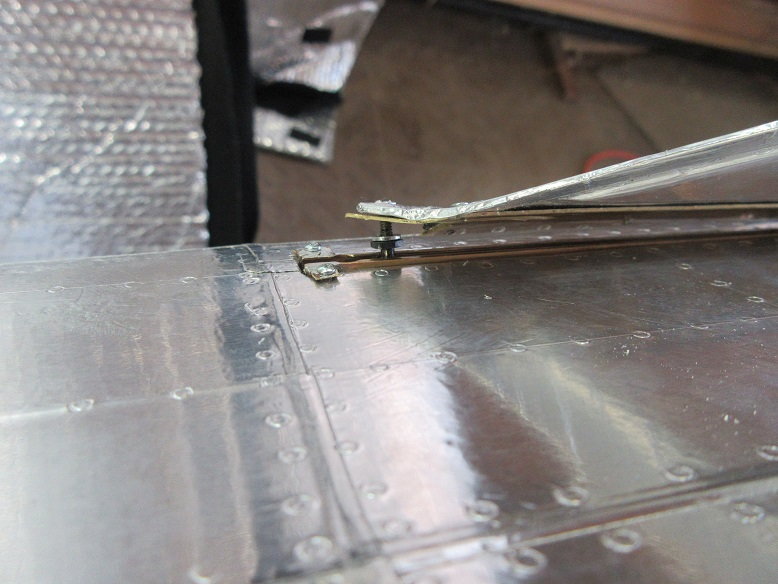
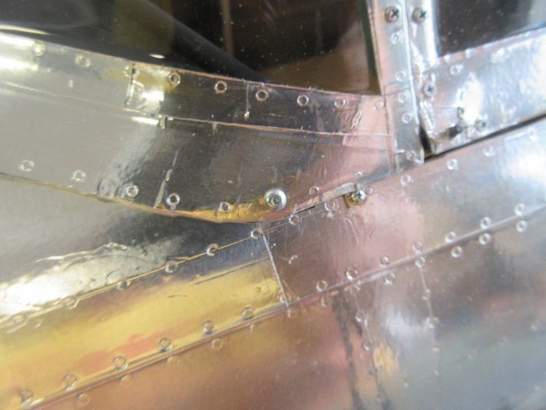
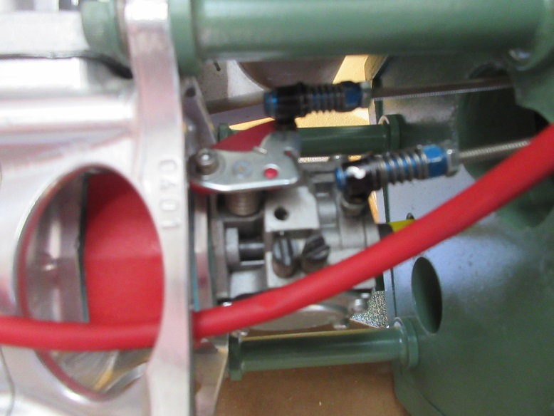
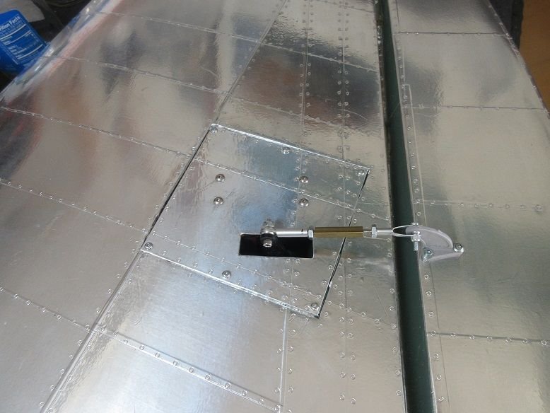
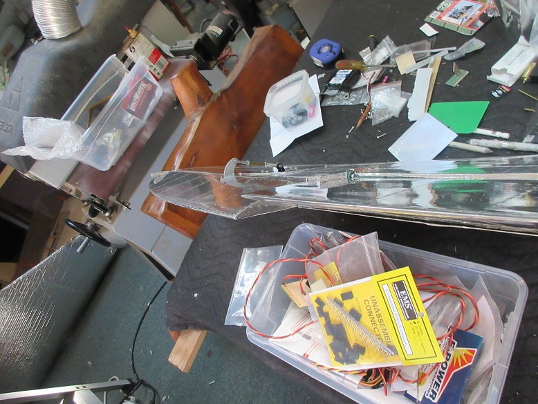
P-47 sliding canopy.
Soldered some L brackets on each end of the brass rails, made a round hole at the back end for the ball socket and used #0X1/4" screws to secure them to the fuse. There is 1/4" square spruce stringers on each side of the rails.
==========
Had to power clean the deck and bench and apply water sealant; now back to planes.
TF kit F6F: replaced the loud muffler with a Zenoah stock muffler on the G-62 and get ready for Saturday's club picnic.
============
P-47 sliding canopy.
Soldered some L brackets on each end of the brass rails, made a round hole at the back end for the ball socket and used #0X1/4" screws to secure them to the fuse. There is 1/4" square spruce stringers on each side of the rails.
Last edited by samparfitt; 07-26-2019 at 03:57 PM.
07-28-2019, 04:40 PM
#183
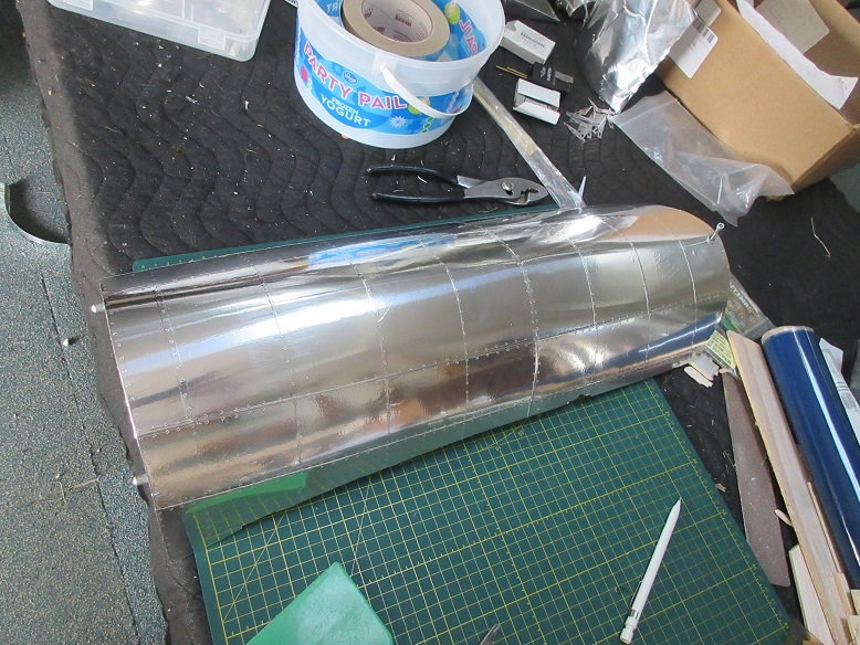
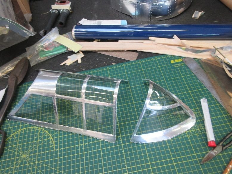
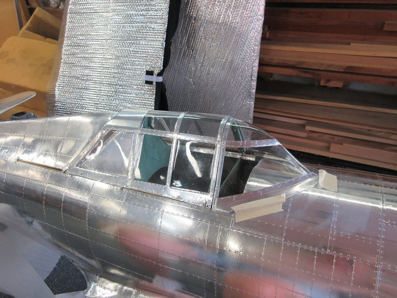
Functioning canopy (cont)
Aluminum tape applied to frame area.
I used to make a FG frame (which was a lot of work) but I think the canopy will hold up with the tape.
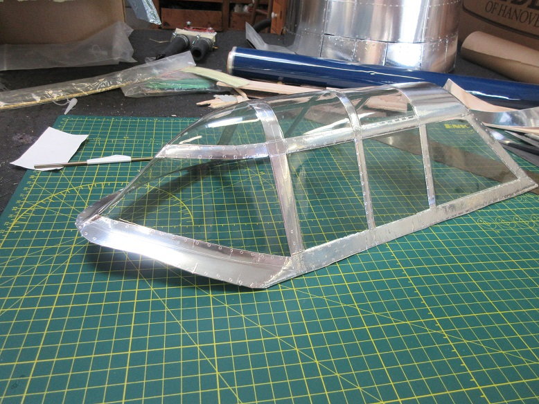
Large and small tin snips to cut canopy in half.
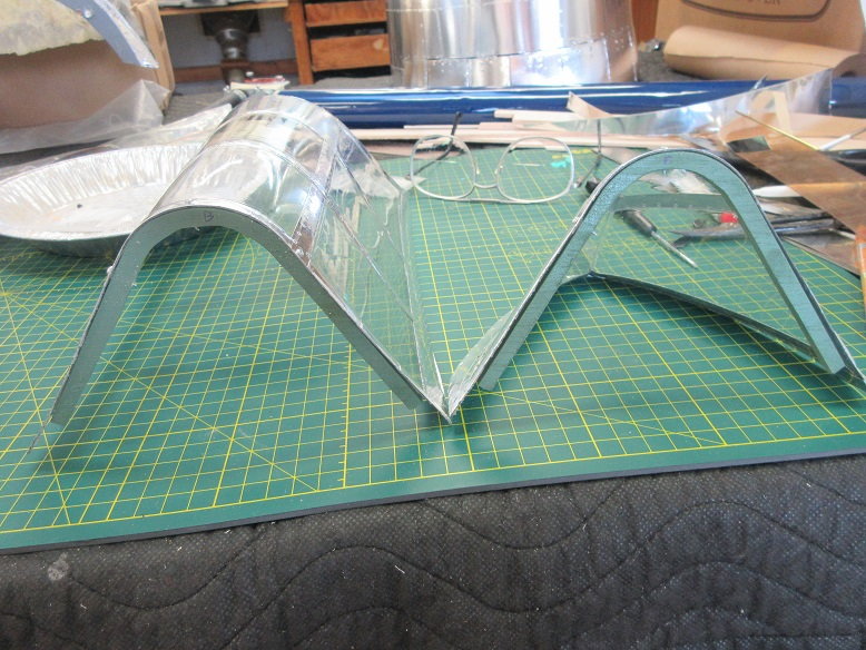
Canopy outline traced on 1/4" thick ply and two canopy supports made.
Canopy screwed to supports.
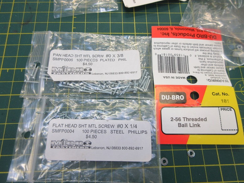
#0X3/8" used for canopy supports.
#0X1/4" used to secure canopy to brass flat stock.
Ball joints used for guides.
Brass stock screwed to canopy to stiffen canopy and excess screw threads ground off with cut off disk.
Brass stock cut to allow ball socket to be perpendicular to the guide rails.
Sliding canopy test fitted with front of canopy taped in place.
Ball socket has to be perpendicular to rail guide to prevent binding.
Aluminum tape applied to frame area.
I used to make a FG frame (which was a lot of work) but I think the canopy will hold up with the tape.
Large and small tin snips to cut canopy in half.
Canopy outline traced on 1/4" thick ply and two canopy supports made.
Canopy screwed to supports.
#0X3/8" used for canopy supports.
#0X1/4" used to secure canopy to brass flat stock.
Ball joints used for guides.
Brass stock screwed to canopy to stiffen canopy and excess screw threads ground off with cut off disk.
Brass stock cut to allow ball socket to be perpendicular to the guide rails.
Sliding canopy test fitted with front of canopy taped in place.
Ball socket has to be perpendicular to rail guide to prevent binding.
08-01-2019, 01:11 PM
#185
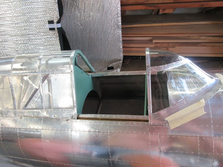
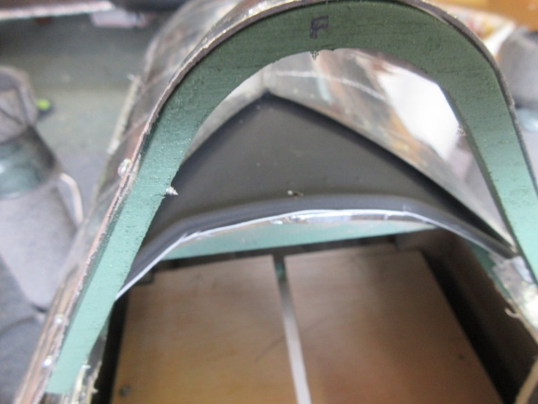
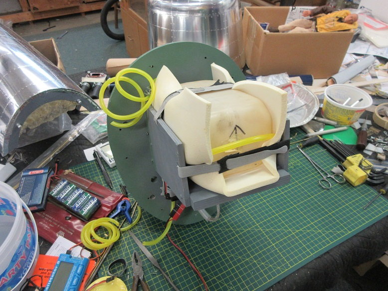
Cockpit and canopy install.
Using Brian's Z P-47 cockpit scale kit from dynamic balsa.
Figure I'd better install the cockpit and then install all hardware around it.
One former needed cutting to open up the cockpit area.
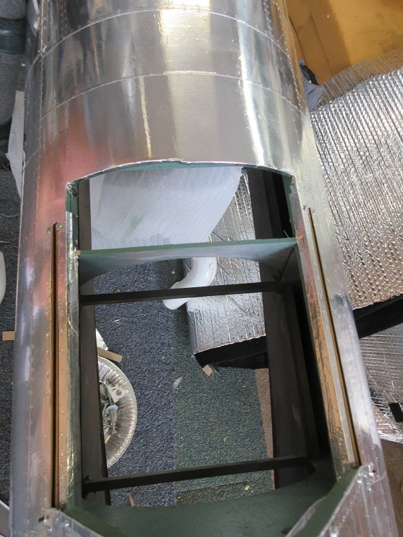
A 1/4" lite ply used for the sub floor. Used ply instead of balsa as everything is screwed in and less likely to have anything vibrating free.
Everything is screwed in so everything can be removed, for PM, etc.
Had to cut the ply in half to insert the sub floor.
Black top of dash cut to match front of canopy.
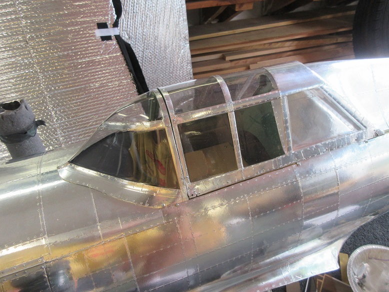
Button head screws used to secure front of canopy to fuse. For now, only installed three screws.
The white edge of the ABC plastic can be touched up with a brush.
Using Brian's Z P-47 cockpit scale kit from dynamic balsa.
Figure I'd better install the cockpit and then install all hardware around it.
One former needed cutting to open up the cockpit area.
A 1/4" lite ply used for the sub floor. Used ply instead of balsa as everything is screwed in and less likely to have anything vibrating free.
Everything is screwed in so everything can be removed, for PM, etc.
Had to cut the ply in half to insert the sub floor.
Black top of dash cut to match front of canopy.
Button head screws used to secure front of canopy to fuse. For now, only installed three screws.
The white edge of the ABC plastic can be touched up with a brush.
08-01-2019, 01:21 PM
#186
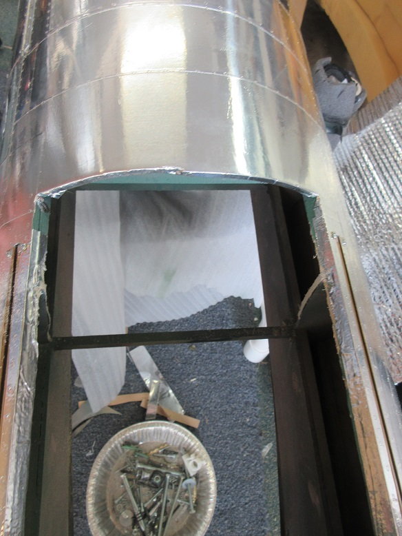
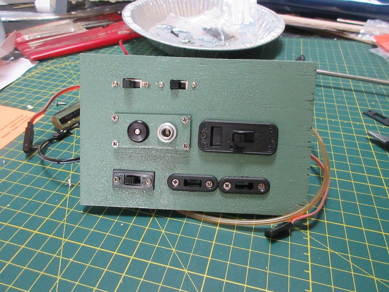
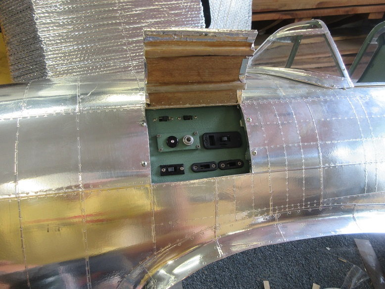
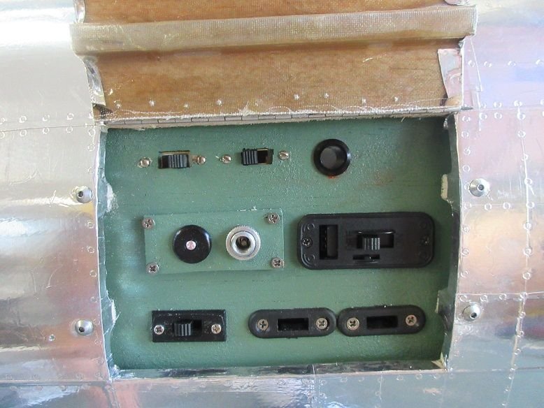
Service panel.
Used some ply and cut out all the holes for controls:
Top two toggles for nav and landing lights.
Air gauge, air filler and ignition switch.
Air always mounted to removable ply as much easier to service these via a removable plate versus accessing the back of the service panel.
JR power safe soft switch and two charging outlets for the two batteries.
They were arranged parallel to the two stringers that are attached to the service panel door to prevent interference with each other.
Last edited by samparfitt; 08-01-2019 at 01:25 PM.
08-01-2019, 03:44 PM
#187
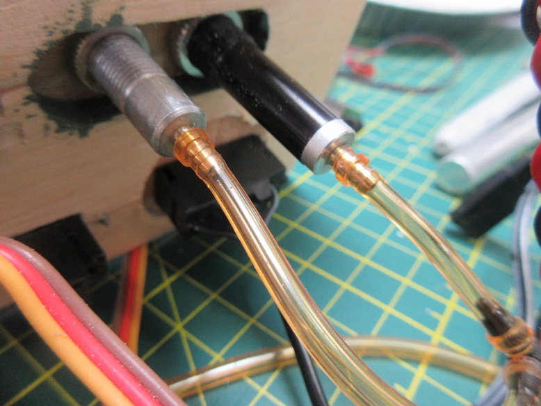
Service panel.
All connections made to back for ease of connecting wires/hoses after panel install.
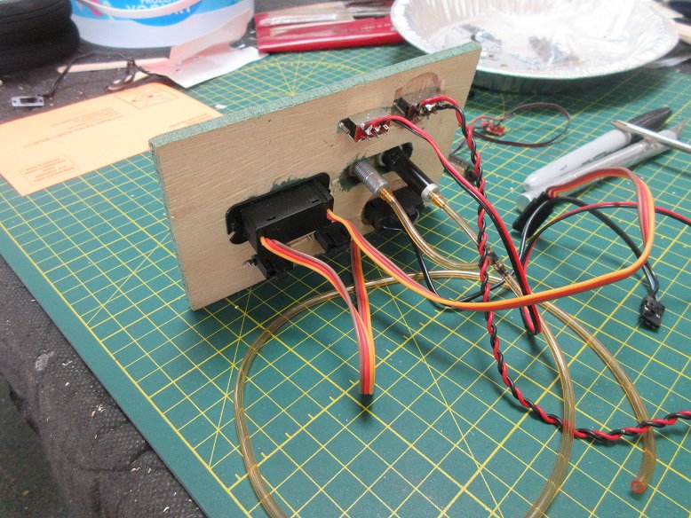
Scott Prossen showed me this on putting a 1/16" wide air collar over the air tube to secure it.
Four large button head screws to secure panel to fuse and makes it removable.
MMMM: forgot the fuel line!
Cockpit:
Dry fitted floor, back and screwed one side panel into the fuse.
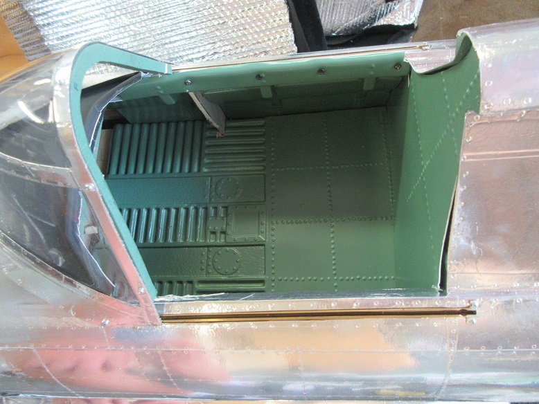
The sides are suppose to be straight but, I find that there, usually, isn't a lot of room for all the 'stuff' that goes on those side panels and they, usually, interfere with the seat/pilot.
I made the sides long (height wise) so they went behind the floor. I cut around the former as I didn't want to make the former thinner and weaken that area.
All connections made to back for ease of connecting wires/hoses after panel install.
Scott Prossen showed me this on putting a 1/16" wide air collar over the air tube to secure it.
Four large button head screws to secure panel to fuse and makes it removable.
MMMM: forgot the fuel line!
Cockpit:
Dry fitted floor, back and screwed one side panel into the fuse.
The sides are suppose to be straight but, I find that there, usually, isn't a lot of room for all the 'stuff' that goes on those side panels and they, usually, interfere with the seat/pilot.
I made the sides long (height wise) so they went behind the floor. I cut around the former as I didn't want to make the former thinner and weaken that area.
Last edited by samparfitt; 08-01-2019 at 04:17 PM.
08-01-2019, 07:51 PM
#188

My Feedback: (1)
Join Date: Sep 2004
Location: Charlotte,
NC
Posts: 112
Likes: 0
Received 0 Likes
on
0 Posts
Sam,
I've been using your build as a reference for my Z47 for the past 1.5yrs. Incredible building skills, my friend! Love the aluminum finish. It's great to see you�ve picked yours back up again to hopefully finish her. I was really hoping you would. You've once again inspired me to finish mine! I'll be watching your finish much more closely now!!
Glenn
Last edited by tgking44; 08-02-2019 at 04:49 AM.
08-02-2019, 05:27 AM
#189
Glenn,
I was hoping to have her done by Aug 1 but that was wishful thinking with flyins to go to and non plane stuff to do. I'll just 'truck along' until it's done.
================
I'll leave the rest of the cockpit install for later. I've got enough done to know where I can install the rest of the hardware, ie servos, receiver, etc.
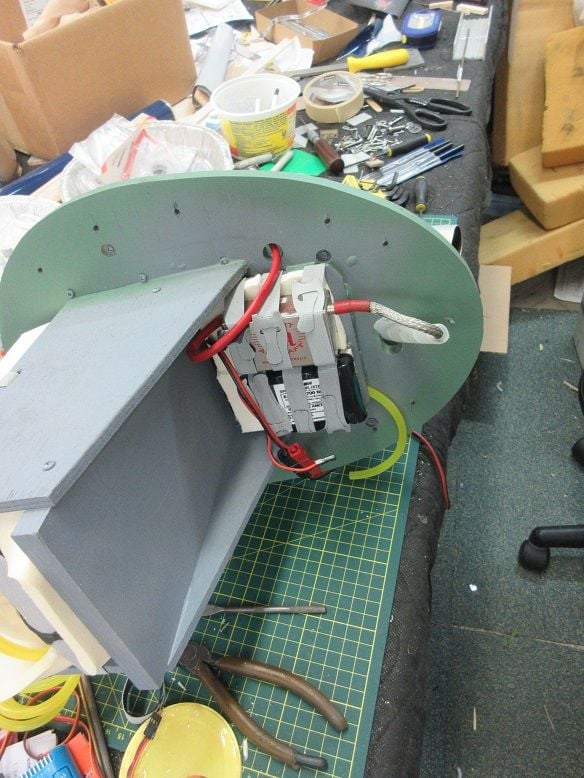
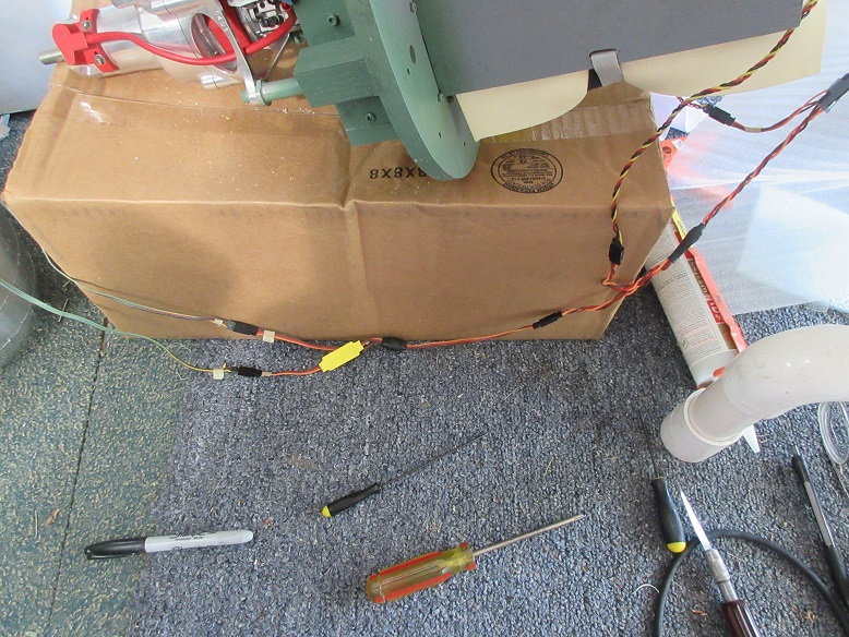
Receiver batteries.
Figure I'll install receiver and batteries, first, as I can now test each servo as it's installed.
Some 1/4" ply cut with slots for velcro.
Dry fit in front bottom of fuse.
Epoxied. Two 4200 ma batteries.
Fuel tank filler installed in service panel.
I was hoping to have her done by Aug 1 but that was wishful thinking with flyins to go to and non plane stuff to do. I'll just 'truck along' until it's done.
================
I'll leave the rest of the cockpit install for later. I've got enough done to know where I can install the rest of the hardware, ie servos, receiver, etc.
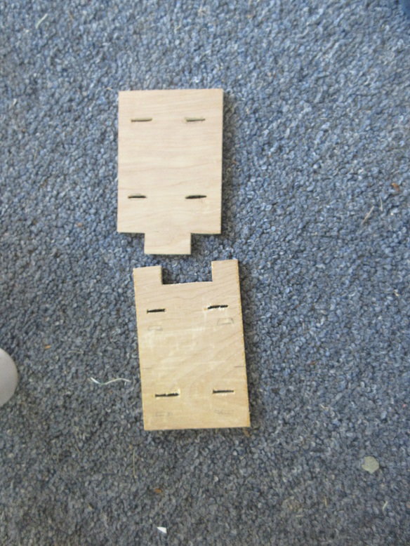
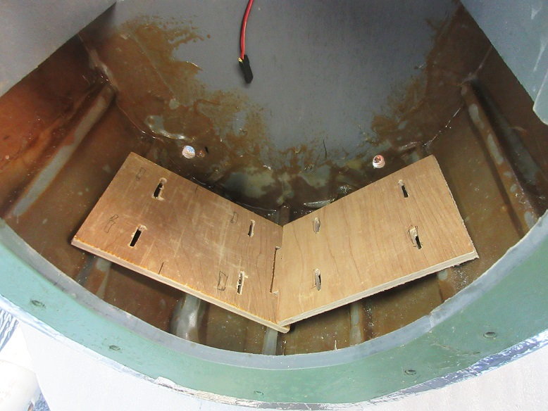
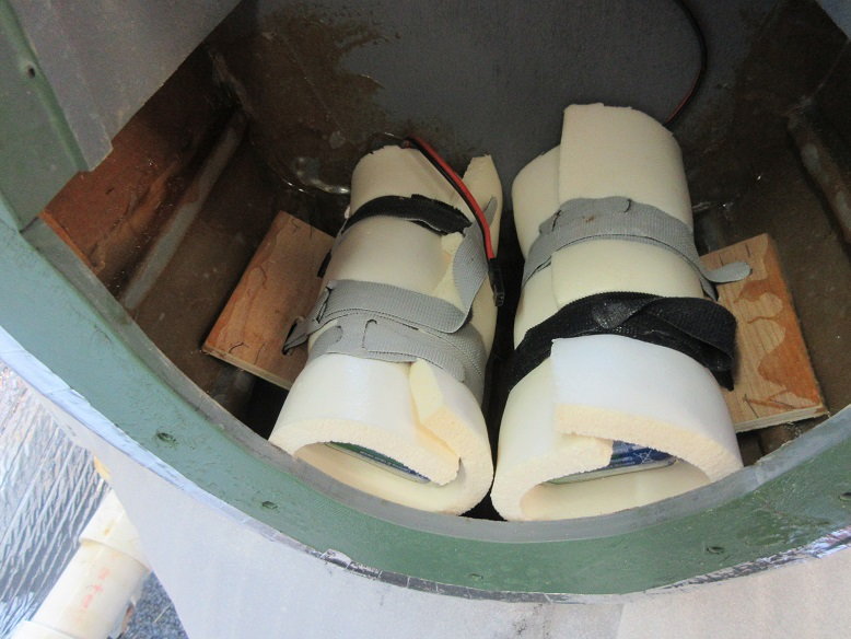
Receiver batteries.
Figure I'll install receiver and batteries, first, as I can now test each servo as it's installed.
Some 1/4" ply cut with slots for velcro.
Dry fit in front bottom of fuse.
Epoxied. Two 4200 ma batteries.
Fuel tank filler installed in service panel.
Last edited by samparfitt; 08-02-2019 at 05:33 AM.
08-02-2019, 01:06 PM
#190
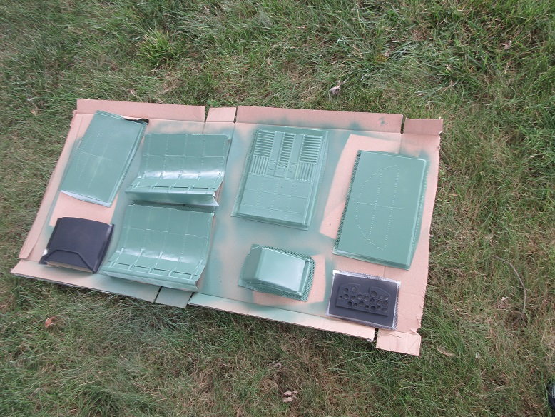
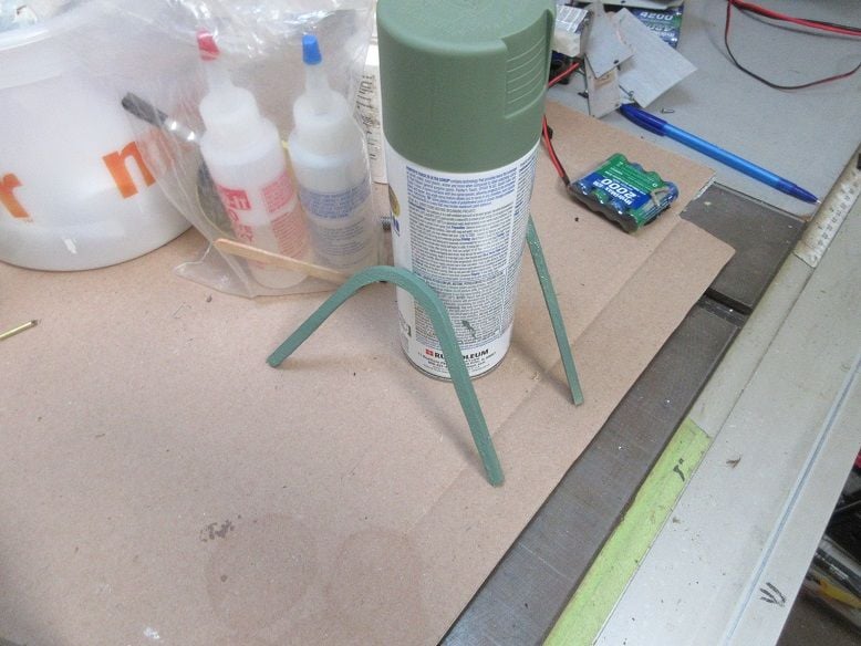
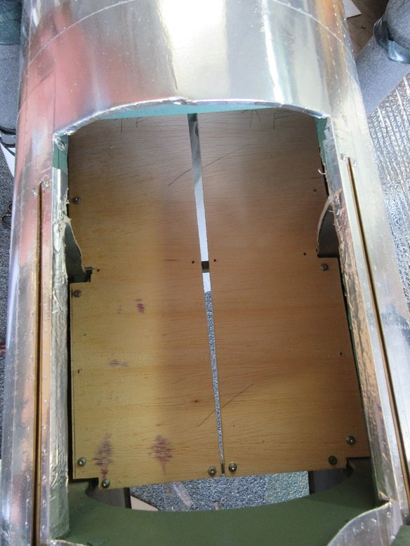
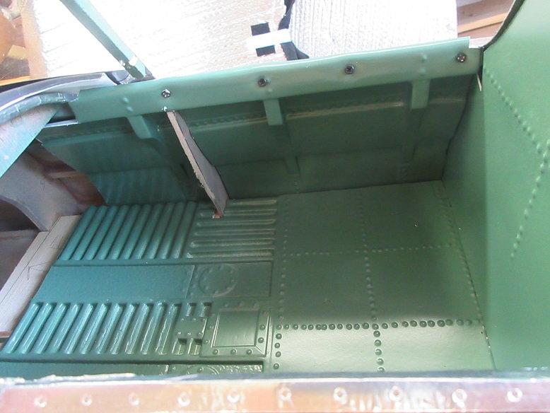
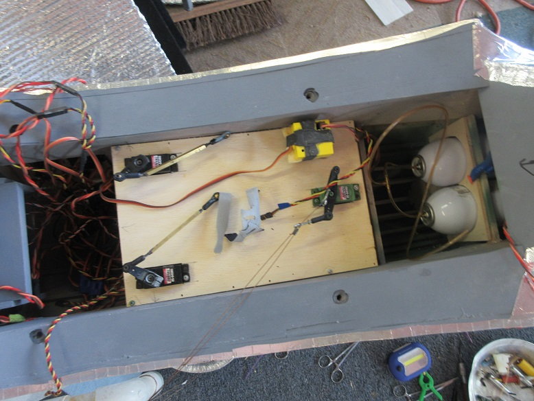
Utility floor:
Two spruce 'runners' were epoxied to each side of the fuse below the cockpit.
Removable fire wall installed to insure no interference with service panel, etc.
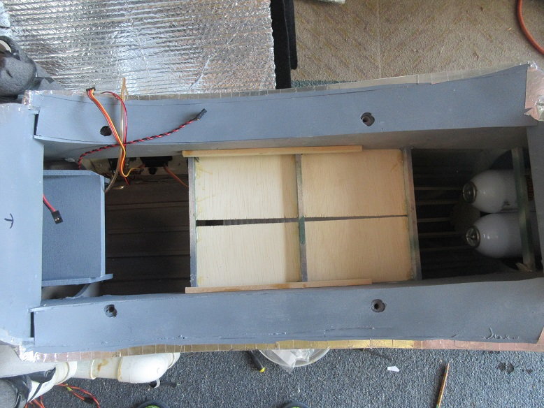
Some 1/4" thick lite ply screwed to the runners to support receiver, etc.
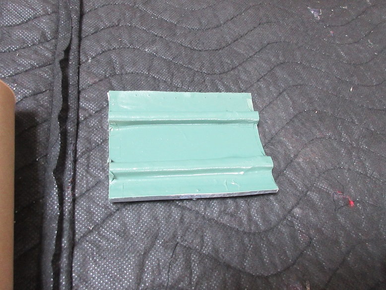
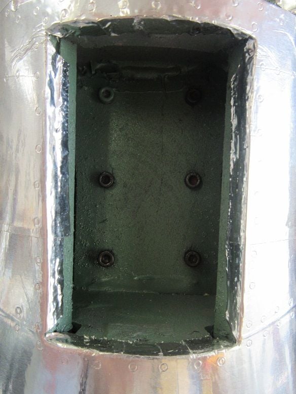
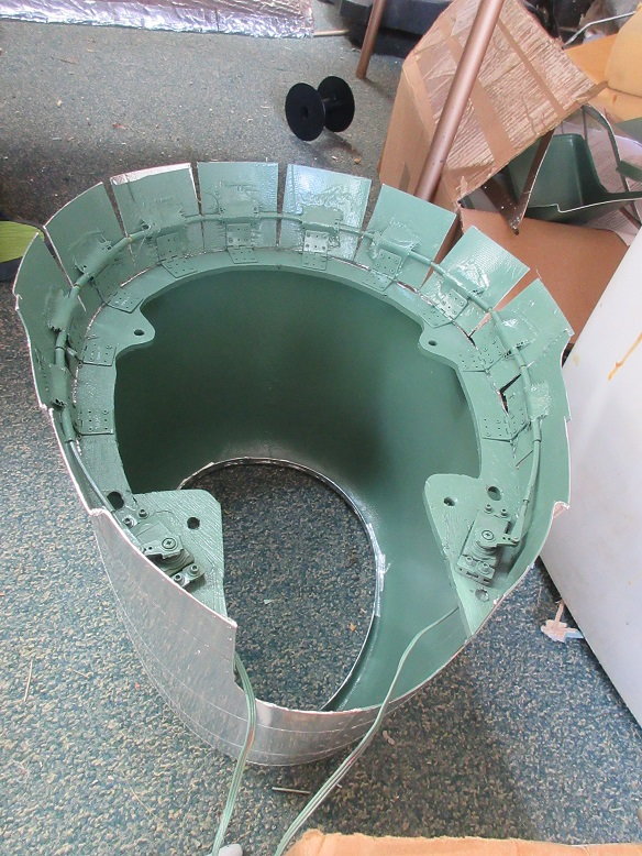
Inside of service panel door painted moss greeen.
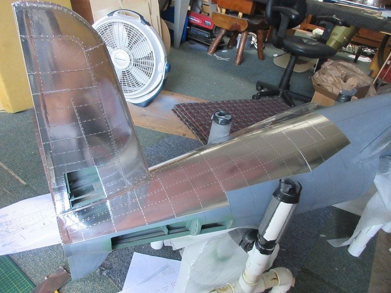
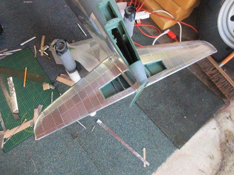
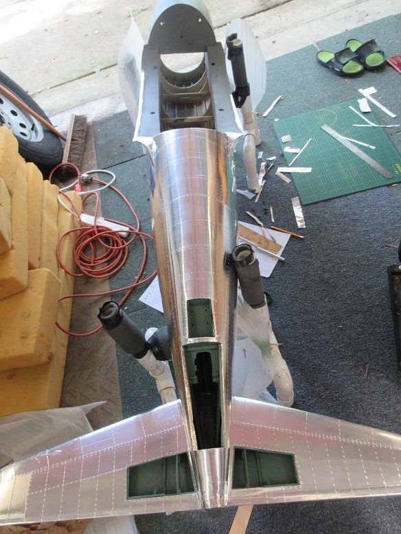
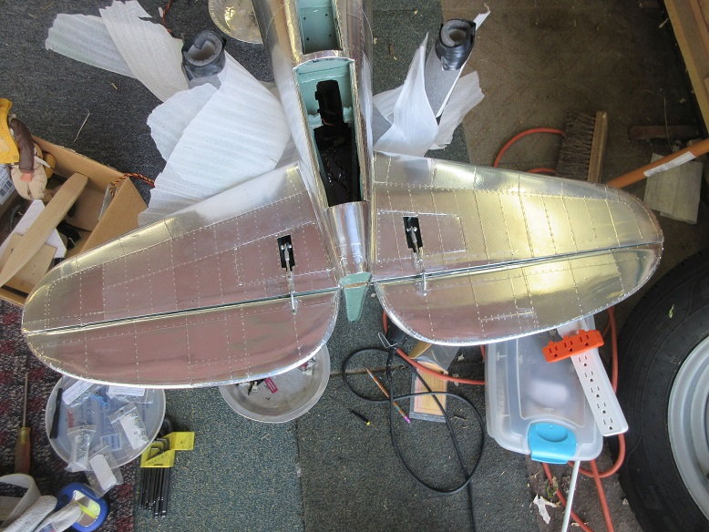
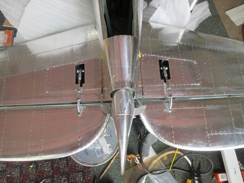
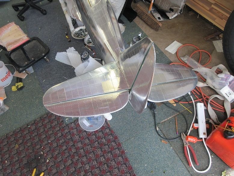
Elevators.
HS-645's screwed into the stab.
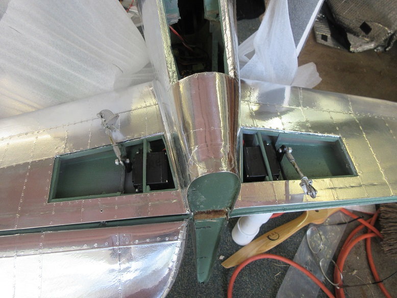
Elevators installed into Robart pocket hinges. Everything is made modular.
Small hole in bottom of stab to access pocket hinge set screw.
End view of pocket hinge.
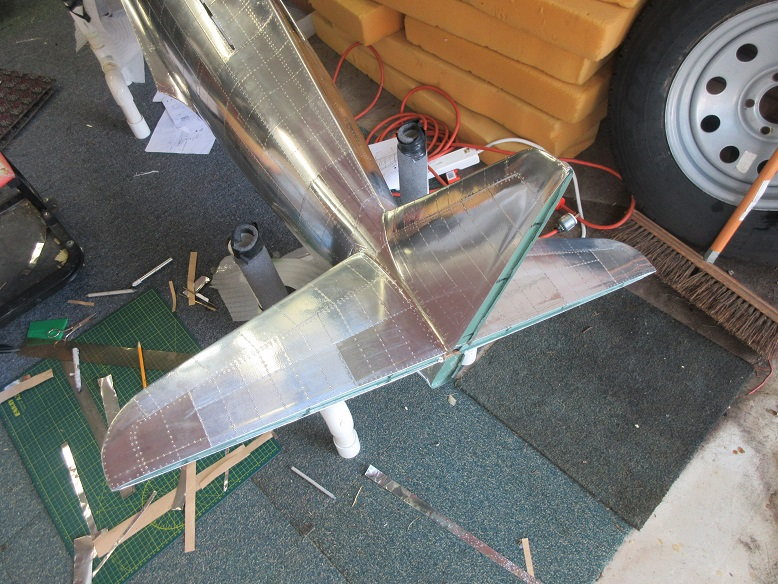
Servo covers installed and elevators checked via the transmitter and receiver.
Ball sockets on all connections and short linkages from servos to moving surfaces.
Button head screws to secure servo covers to stab.
Large holes needed as servo arm is short and allow room for ball sockets.
Two spruce 'runners' were epoxied to each side of the fuse below the cockpit.
Removable fire wall installed to insure no interference with service panel, etc.
Some 1/4" thick lite ply screwed to the runners to support receiver, etc.
Inside of service panel door painted moss greeen.
Elevators.
HS-645's screwed into the stab.
Elevators installed into Robart pocket hinges. Everything is made modular.
Small hole in bottom of stab to access pocket hinge set screw.
End view of pocket hinge.
Servo covers installed and elevators checked via the transmitter and receiver.
Ball sockets on all connections and short linkages from servos to moving surfaces.
Button head screws to secure servo covers to stab.
Large holes needed as servo arm is short and allow room for ball sockets.
Last edited by samparfitt; 08-02-2019 at 01:10 PM.
08-06-2019, 12:02 PM
#191
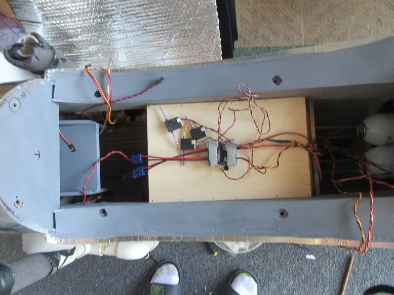
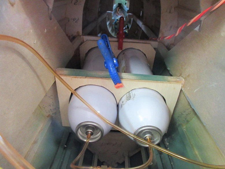
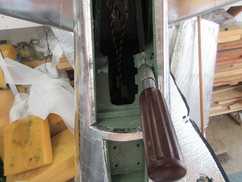
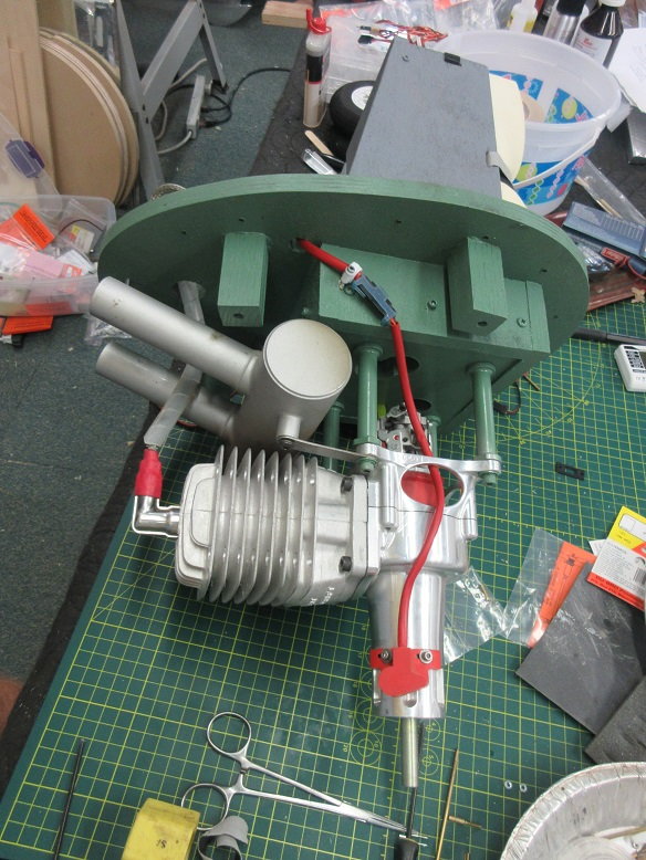
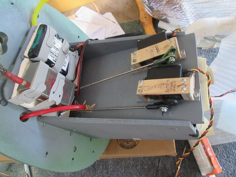
Two large air tanks installed behind the cockpit.
After the ply air tank supports epoxy dried, clear caulk used to secure tanks to supports.
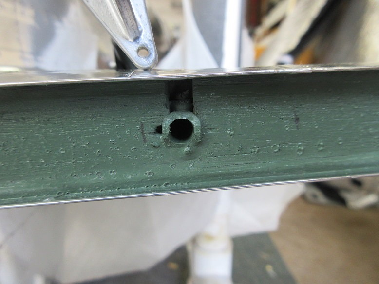
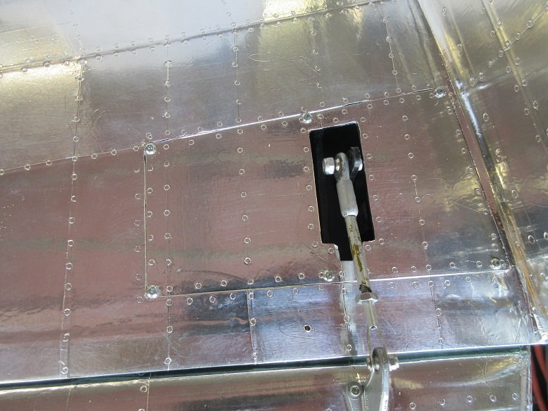
Rudder servo and pull/pull lines installed.
Some Sullivan golden rod used for wire guides.
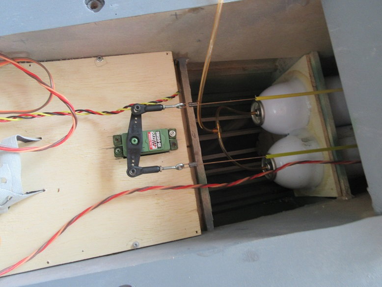
A long 1/8" diameter drill bit used to drill into side of fuse and the next former forward to route the sullivan golden rod.
Some aluminum tape will be used to cover up the yellow.
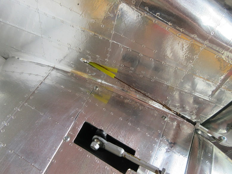
Had to cut some ply out to insert the giant sierra tail wheel gear.
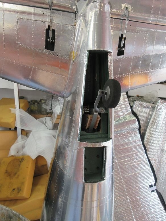
Six screws, forward of the tail wheel gear well, holds the gear to a ply plate.
After the ply air tank supports epoxy dried, clear caulk used to secure tanks to supports.
Rudder servo and pull/pull lines installed.
Some Sullivan golden rod used for wire guides.
A long 1/8" diameter drill bit used to drill into side of fuse and the next former forward to route the sullivan golden rod.
Some aluminum tape will be used to cover up the yellow.
Had to cut some ply out to insert the giant sierra tail wheel gear.
Six screws, forward of the tail wheel gear well, holds the gear to a ply plate.
Last edited by samparfitt; 08-06-2019 at 12:07 PM.
 08-07-2019, 12:59 PM
#196
Mike,
The tape is from Home Depot and, since it's used for duct work, they don't list the thickness.
I've used other brands and the duct tape is thicker than other brands.
Thicker may sound like a negative but I like the thicker tape as it's easier to apply. I found thinner to be a little more difficult to apply as it seems to be more sensitive to getting wrinkled before applying it to the surface. The thinner stuff does wrap around compound curves better.
For me, the extra weight is not a factor: when doing a 40 pound planes, if it weighs another pound due to paint/tape is not critical (and I'm guessing if it weighs another pound).
For me, it takes about 130 hours to put tape and rivets on a plane but, if you get any hanger rash, it's quick and easy to fix.
I never worry much about weight. A ziroli flies well whether it's 32 pounds or 42 pounds. Personally, I prefer heavier planes: the wind doesn't move them around as much, they seem to turn more scale and when they land, you don't have to worry about it floating back into the air. All I do is light aerobatics with warbirds and weight is not much of a factor for such maneuvers.
Last edited by samparfitt; 08-07-2019 at 01:04 PM.
08-07-2019, 04:03 PM
#197
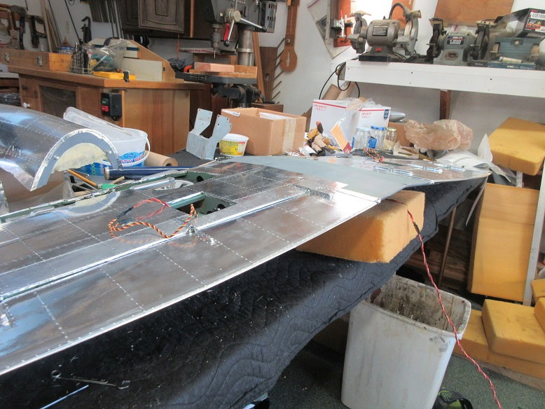
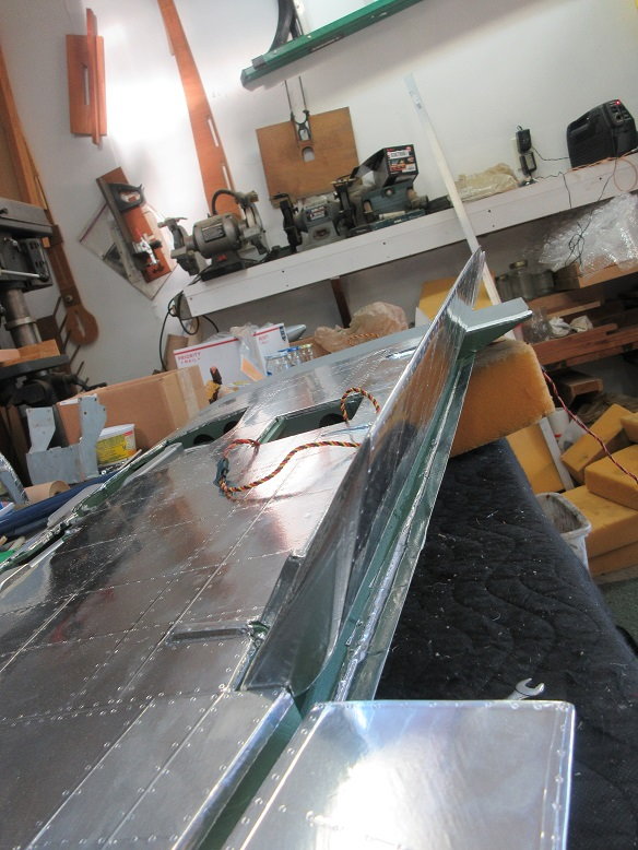
Wing.
Flap/aileron install.
Before:
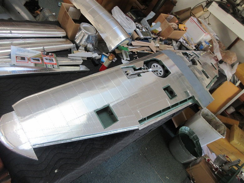
Dubro heavy duty hinges for ailerons.
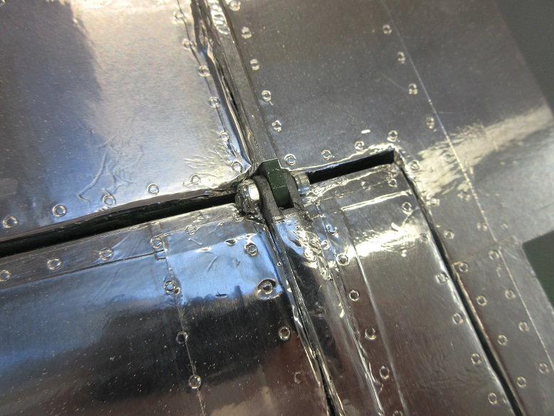
Homemade fowler type hinges for flaps.
G10 used for flap hinges with 4X40 bolts/nuts.
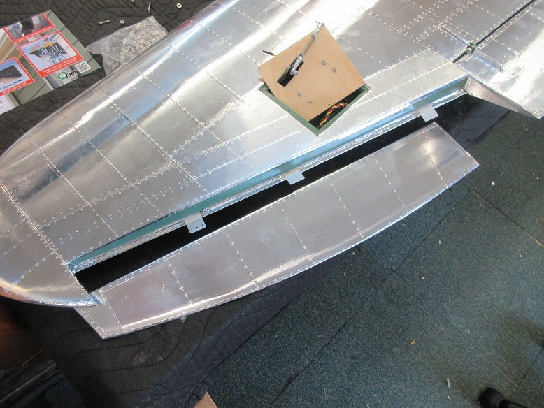
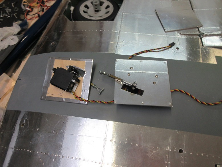
Flap servo.
UP: servo arm at 90 degrees.
Down: servo arm and push rod inline with with other.
Ball joint used.
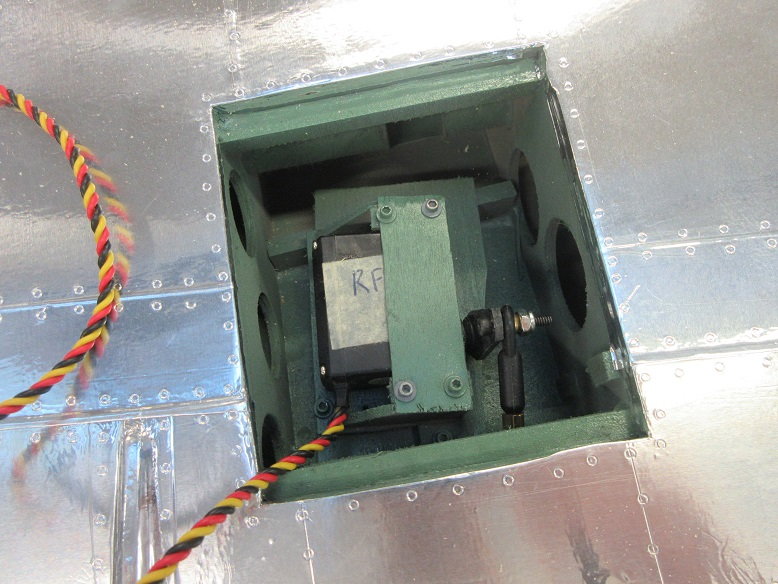
4/40 bolt/nut secure ball joint pushrod to flap control horn. Washer next to bolt head to insure ball joint doesn't come off.
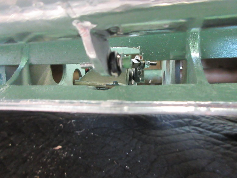
Bottom view.
Top view.
Flap/aileron install.
Before:
Dubro heavy duty hinges for ailerons.
Homemade fowler type hinges for flaps.
G10 used for flap hinges with 4X40 bolts/nuts.
Flap servo.
UP: servo arm at 90 degrees.
Down: servo arm and push rod inline with with other.
Ball joint used.
4/40 bolt/nut secure ball joint pushrod to flap control horn. Washer next to bolt head to insure ball joint doesn't come off.
Bottom view.
Top view.

 08-09-2019, 09:26 AM
#200
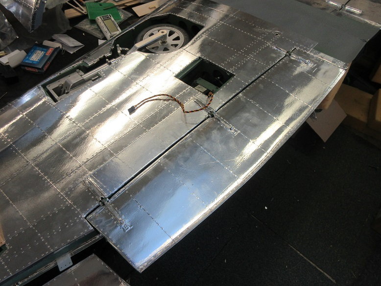
Wing (cont)
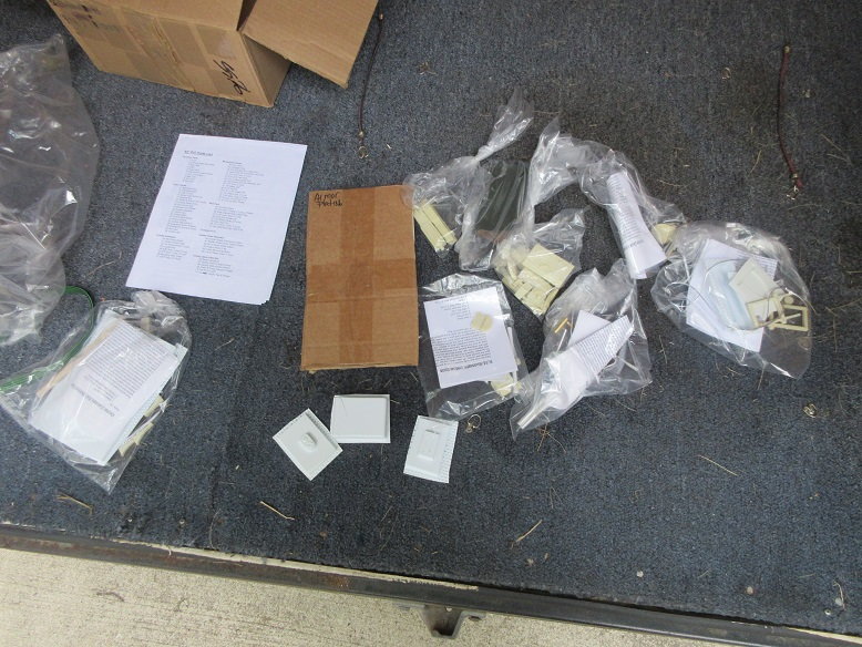
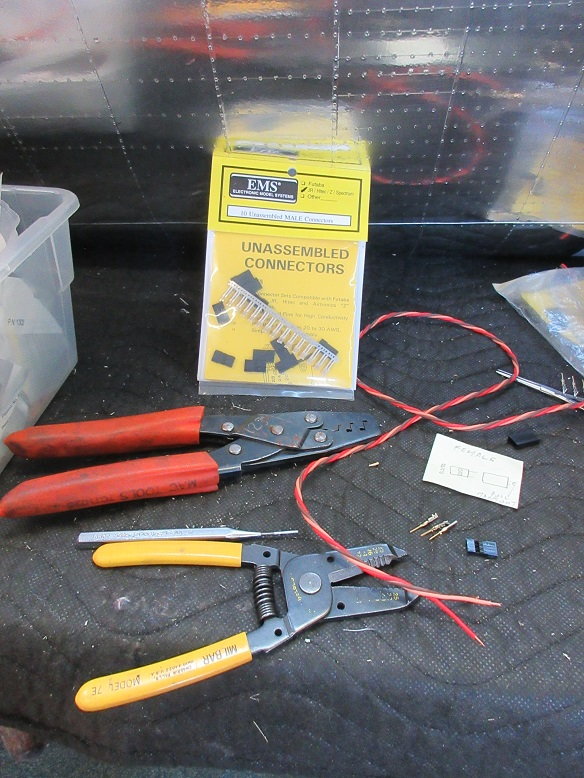
Nav lights: have some kits I ordered 3-4 years ago.
Comes with control module and more LED's than I'll use.
Nice in that I can plug the control module into any receiver port to power it.
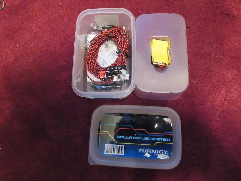
Wire leads are about 2' long and I need them much longer. Cut the end connect off and will keep it for connecting to the control module in the fuse. Used some CAT-5 cable to extend the length of the wires to reach the center of the wing.
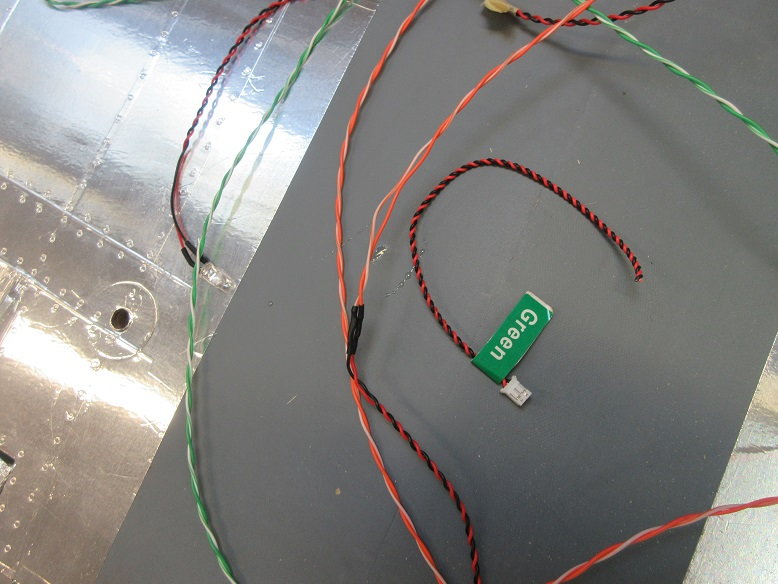
Wing tip LED.
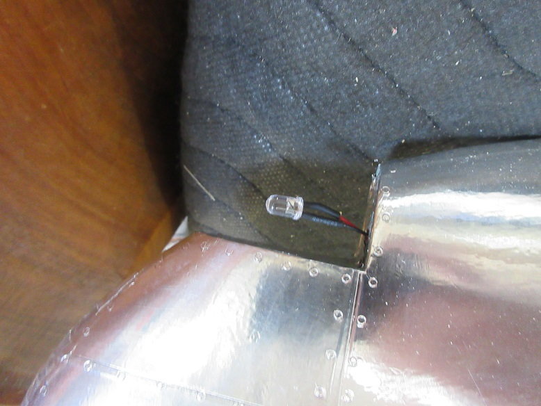
Routing tubes were pre-built in when building the wing.
Wing tip leads to aileron well.
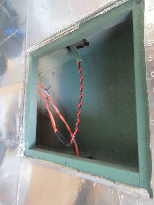
Some 20 gauge wire extensions made.
Aileron linkage installed. Servos are hatch mounted. Robart ball control horn and dubro ball linkage.
Ailerons tested via receiver.
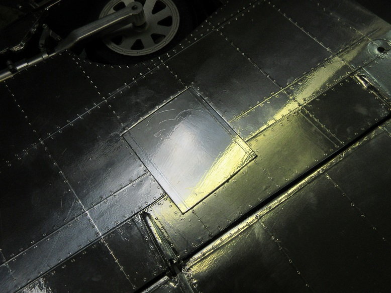
Flap hatches covered and secured.
Nav lights: have some kits I ordered 3-4 years ago.
Comes with control module and more LED's than I'll use.
Nice in that I can plug the control module into any receiver port to power it.
Wire leads are about 2' long and I need them much longer. Cut the end connect off and will keep it for connecting to the control module in the fuse. Used some CAT-5 cable to extend the length of the wires to reach the center of the wing.
Wing tip LED.
Routing tubes were pre-built in when building the wing.
Wing tip leads to aileron well.
Some 20 gauge wire extensions made.
Aileron linkage installed. Servos are hatch mounted. Robart ball control horn and dubro ball linkage.
Ailerons tested via receiver.
Flap hatches covered and secured.