


Kolm 135 install in CARF Mustang
 11-16-2014, 05:09 PM
#1

A lot of people have watched the youtube video of this motor in the spitfire and mustang. The sound is what got me interested. I'm not really into Mustangs, but love the sound of the Kolm! I bought a used mustang from Greg Wright here on RCU, and ordered the Kolm from Gotz at Vogelsang. This will be kind of a review of the motor and a how to on mounting it.
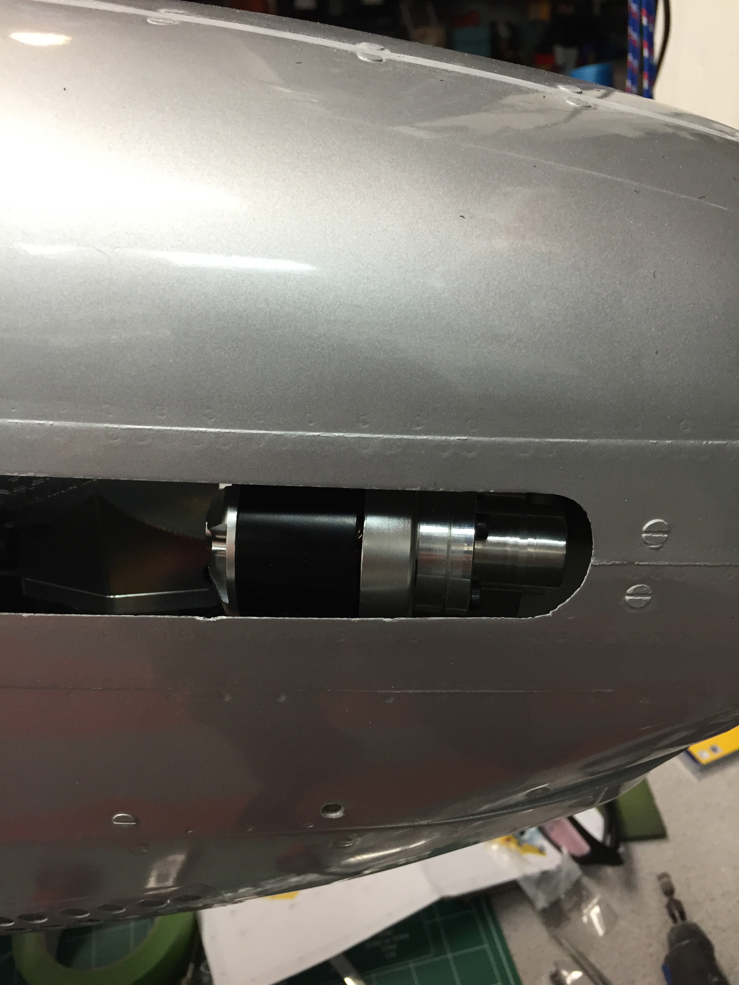
I got the motor last week, it is a work of ar!. I think the only castings are on the walbro carbs. Everything is machined. It also came with a mounting kit specifically for the mustang. Not sure I would have purchased the motor without it. It has six rubber soft mounts that requires two firewalls. I am almost done with the mustang, waiting not he motor was holding me up. The supplied hardware and wood mounting kit was a great start, but needed a lot of trimming. A few of the wood parts were missing or way off in size. The rubber bushings that are supplied use 6mm bolts. The holes in the motor are 5mm. It was hard to take a drill to my brand new shiny Kolm! three of the four, I tapped. The fourth cannot screw in because of a plastic housing on the back of the motor. Weird that they designed it with uneven mounting on the back. I had to cut half of one of the rubber bushing off to make everything sit flush.
I have the keleo scale exhaust, unfortunately the electric starter gets in the way and I might not be able to use both. I need to talk to Kelvin about modifying it.
I ordered the electric start version, it did not come with an ESC, I have the electric starters for my DLE 55, they come with a a module to control it. Waiting on Hans to advise me on what I need.
Here are a bunch of pics, I'm halfway done, I'll update as I go.
 11-16-2014, 07:52 PM
#2

My Feedback: (24)
I think the early videos are with the 3 cylinder 150, then later they installed a 4 cylinder 200. Personally I think the 3 cylinder version sounds better, but that's just me.
Nevertheless, this should be an awesome plane, with a very cool sound once complete! Will be following along with great interest
Nevertheless, this should be an awesome plane, with a very cool sound once complete! Will be following along with great interest
11-16-2014, 09:06 PM
#3
Join Date: Nov 2013
Location: Fair Oaks, CA
Posts: 144
Likes: 0
Received 0 Likes
on
0 Posts
Looks pretty awesome DrScoles! I just ordered the IL135's little brother, the EZ65 a little over a week ago through Gotz. It will be going into a Yellow Aircraft P-40.
How long did it take for your engine to arrive? I'm pretty excited!
How long did it take for your engine to arrive? I'm pretty excited!
11-17-2014, 01:56 PM
#4
They said six weeks, got it in seven. I was more than happy with that. Got all of the baffle done this morning. There is no manual for this. Obviously, overheating is a concern. I need to figure out if I have to cut a hole in the bottom of the fuse forward of the wing, or is the exit out the back radiator vents enough? My other concern is the perforated cooling vents on each side. Are they going to disrupt the airflow in the baffle? I'm putting telemetry on this plane with temp sensors on both heads, I'll just have to do some testing. Pretty easy to put covers inside to close up those holes if necessary. For now, they're open. I'm familiar with the opening being 1/3 the size of the exit rule, but not sure if introducing other holes along the way will disrupt things.
Hard part is over, indexing the two firewalls was a PAIN IN THE ASS. The motor is very heavy, and you have to reach through the cockpit to tighten the bolts, while you're worried about dropping the motor and dinging up the bottom of the fuse. Not sure how many times took the motor in and out….
Next up is 6oz bidi carbon from the front of the cockpit to the firewall. I took the nose off the CARF P-47 4" behind the firewall and saw that two CARF corsairs did the same trick last summer on dead stick landings. There just isn't enough reinforcement in the front of these. The p-47 and corsair are obviously anemic, not sure about this mustang, but not gonna take any chances. Unfortunately, on the P-51, I don't think I need the extra weight up front.
11-17-2014, 06:32 PM
#5
Join Date: Nov 2013
Location: Fair Oaks, CA
Posts: 144
Likes: 0
Received 0 Likes
on
0 Posts
I can't imagine having any issues with the P-51 being anemic with that engine installed! Does the engine have the 270 degree crank in it? I'm assuming you have not ran the engine on a test stand?
Gotz informed me between 4 to 8 weeks for the EZ65, hopefully it will arrive before Christmas!
Gotz informed me between 4 to 8 weeks for the EZ65, hopefully it will arrive before Christmas!
11-18-2014, 10:32 PM
#7

Join Date: Jul 2006
Location: N�rb�, NORWAY
Posts: 91
Likes: 0
Received 0 Likes
on
0 Posts
Hello,
Looks wery good! I am starting in some weeks on the same plane With the Kolm 150 and you give good inspiration:-) Have you found out With the el starter and ESC ?
Brg Geir
Looks wery good! I am starting in some weeks on the same plane With the Kolm 150 and you give good inspiration:-) Have you found out With the el starter and ESC ?
Brg Geir
11-19-2014, 07:42 AM
#9
Got up early enough to do a little carbon work. I'm not really worried about rotational/torque forces (should I be?) More the shear weight of the motor stressing the area behind the firewall. Any structural engineers in the house? The other CARF planes I have are notoriously weak here. Ask me know I know…..


11-19-2014, 10:20 PM
#10

Wow... And the Jug and Corsair are designed around the Moki engines too. So your suggesting I look into strengthening the firewall area of my Corsair?
On the P-51 since it was never designed for the Kolm engine or the kind of power it makes Id say its a very good idea to beef it up AND look at the rest of the plane while your at it!
How did the firwall fail on your Jug? Rough landing?
On the P-51 since it was never designed for the Kolm engine or the kind of power it makes Id say its a very good idea to beef it up AND look at the rest of the plane while your at it!
How did the firwall fail on your Jug? Rough landing?
11-19-2014, 10:30 PM
#11
Join Date: Jul 2006
Location: N�rb�, NORWAY
Posts: 91
Likes: 0
Received 0 Likes
on
0 Posts
That is not good! I am in the final stage of my carf corsair With moki 300 and think i need to make make some carbonwork myself!
The P51 is normal fibreglass and not in composite sandwitch so i think this makes it stronger!
Geir
The P51 is normal fibreglass and not in composite sandwitch so i think this makes it stronger!
Geir
11-20-2014, 12:04 AM
#12

Hello!
Your installation looks good! i see you are using the installation-kit from Kolm.
i�m also a kolm pilot and i�m happy to see that the engines are now available in USA :-)
maybe i can give you a answer if you have any questions.
Tom
Your installation looks good! i see you are using the installation-kit from Kolm.
i�m also a kolm pilot and i�m happy to see that the engines are now available in USA :-)
maybe i can give you a answer if you have any questions.
Tom
 11-20-2014, 03:09 AM
#14
:-)
A short video for you... will motivate you in your work on the plane. me and my friends with kolm-Warbirds.
https://www.youtube.com/watch?v=vOE2...2_c1UkaAwvrppA
A short video for you... will motivate you in your work on the plane. me and my friends with kolm-Warbirds.
https://www.youtube.com/watch?v=vOE2...2_c1UkaAwvrppA
11-20-2014, 07:47 AM
#15
If you look at the corsair, from the firewall back, all there is is a 2" carbon tape along the top. Not enough in my opinion. We need the weight, so it doesn't make sense not to beef it up. I know of two corsairs that broke mid fuse last summer. The P-47 had no reinforcement at all. So, we're relying on foam and a thin layer of glass to support a 12 pound engine and another few pounds of lead. The P-51 has so many curves and angles that I think its probably inherently stronger. I still don't trust it. The repair job on the P-47 sucked, and I'm not even doing all the work!
I've already done the reinforcing on the corsair. Its in storage, or I'd share some pics. I took 6" 5.9oz carbon tape and ran it from the firewall back past the cockpit on the sides, and up to the cockpit on the top. Gary Prince had one crack in half right at the cockpit from a belly landing. To make it worse for me, I put a hatch on top of the corsair. I laid carbon down before I cut it, but didn't think to beef up the sides until the P-47 experience and what Gary went through.


I weighed both the kolm and the moki 250 last night, surprised the kolm beat it! I knew it wasn't ten pounds.


I've already done the reinforcing on the corsair. Its in storage, or I'd share some pics. I took 6" 5.9oz carbon tape and ran it from the firewall back past the cockpit on the sides, and up to the cockpit on the top. Gary Prince had one crack in half right at the cockpit from a belly landing. To make it worse for me, I put a hatch on top of the corsair. I laid carbon down before I cut it, but didn't think to beef up the sides until the P-47 experience and what Gary went through.
I weighed both the kolm and the moki 250 last night, surprised the kolm beat it! I knew it wasn't ten pounds.
11-20-2014, 07:49 AM
#16
:-)
A short video for you... will motivate you in your work on the plane. me and my friends with kolm-Warbirds.
https://www.youtube.com/watch?v=vOE2...2_c1UkaAwvrppA
A short video for you... will motivate you in your work on the plane. me and my friends with kolm-Warbirds.
https://www.youtube.com/watch?v=vOE2...2_c1UkaAwvrppA
Awesome Tom! If you could take a pic of the bottom of your mustang cowl area, I would greatly appreciate it! I have no idea how big a hole I have to cut for the air to exit. I know some will go through the fuse and out the radiator vent, but pretty sure I need to make an exit hole on the left side of the cowl on the bottom in front of the wing?????
11-20-2014, 08:57 AM
#17
Thats a pretty heavy two cylinder engine! Interesting...
The hot air exhausts can have a screen to dress up the opening you make in the nose area, just throwing that out there.
Also the total area of the exits should be 3.5-4x the area of the intake but should also be in an area of low pressure to promote evacuation of the hot air.
The natural choice being the two belly radiator exhaust doors presents the problem of hot air running through the interior of the fuse. The ducting made by a couple modellers makes sense but is that available as a kit?
11-20-2014, 09:46 AM
#18
Just to jump in , have you thought about fitting a small edf unit into the fire wall so it draws most of the hot air out ?only needs to run at 50 % ish, also gives it a kind of supercharger sound if you use your imagination : )
I've seen it on a couple of models and seems to work well. Would have to look at how ducting could be routed through the fus and out the rear belly vent ?
Been meaning to get going with my carf p-51 for far to long now, and it may have twisted my arm on the choice of engine for it.
Its a real shame about your P-47, Graham had done a fantastic job on the paint , he will be getting his mitts on my p-51 when I stop faffing around with other models
look forward to your progress
Toby
11-20-2014, 10:03 AM
#19
Yes, big bummer on the P-47. Luckily, I have a friend who is a very gifted painter, paints cars for a living. He has the liquid metal paint and the skill set to get close to what Graham did. The riveting was easier than I thought. It will be very close in appearance and dramatically stronger!
There are lots of people using the Kolm without all the ducting and fans, don't wanna go there. I can't see how you could do it and have a full cockpit and anywhere to place the radio gear anyway. I'll be using telemetry on this plane, temp sensors on both cylinders, I'll get it figured out. Gonna start conservative with the holes, I can always enlarge them. The baffle kit Hans came up with is slick. Just need to fire it up and see how it goes. Spent some time on the servo tray and radio tray to hold the Robbe 2018 and batteries last night. Its getting close to going to paint!
There are lots of people using the Kolm without all the ducting and fans, don't wanna go there. I can't see how you could do it and have a full cockpit and anywhere to place the radio gear anyway. I'll be using telemetry on this plane, temp sensors on both cylinders, I'll get it figured out. Gonna start conservative with the holes, I can always enlarge them. The baffle kit Hans came up with is slick. Just need to fire it up and see how it goes. Spent some time on the servo tray and radio tray to hold the Robbe 2018 and batteries last night. Its getting close to going to paint!
11-20-2014, 11:08 AM
#20
Hello Guys!
Im Using the Engines without ducted Fans or so. I have the il150 in mY Spitfire with telemetry on 2zylinders. After 100 flights or more i can Tell you everything about the Cooling. The cooling in the Mustang with the Il135 was also made by me. Its the Same like You do it here.
It Sounds simple:
front in-all fresh air On One Side-all the air thru the Zylinders-hot air Out in the back before the Firewall.
At the Mustang You have to close the small holes in the intake-Side. And downside near the Firewall You have to Cut Out For the hot air.
You can see it at my spitfire.
Tom
11-20-2014, 11:18 AM
#21
I Try to get the Fotos for Installation in Mustang For you. I can do in the Office tomorrow. Photos by phone dosnt work... Don't know.
Sorry For my bad English
Tell my when you will install the engine fixed. So i Tell you my Tricks For a Working cooling.
Sorry For my bad English
Tell my when you will install the engine fixed. So i Tell you my Tricks For a Working cooling.

