


P 51d mustang 60cc hangar 9 build


 11-12-2015, 06:41 AM
#27
Well I guess I should get back to this before it gets totally skyjacked.
I built this jig to make the offsets for the gear door stops and it worked well. It's in the manual. I put a small amount of petroleum jelly on it so the CA glue would not stick to it.

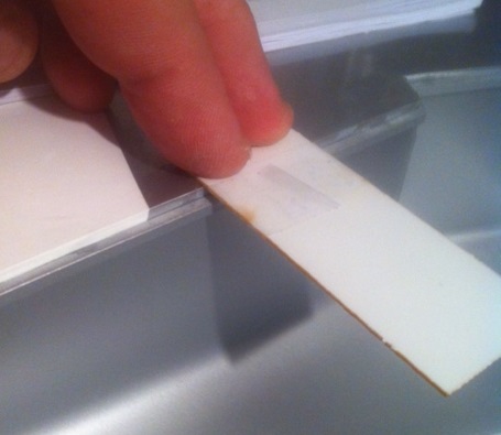 After the flanges where in place it was time to check how the door fit. Here I found a problem.
As you can see from the picture the gear doors on the left side do not fit. The door, itself, was the right size. The wheel well itself was built too wide. When I received the kit I noticed that there where 2 sets of gear doors and one of them had been opened. This lead me to believe that this was a returned kit. The previous buyer had the same problem and Hangar 9 sent him a new set of gear doors which still would not fit. After much argument and pictures from different angles, sent to hangar 9, They sent me a new center section of the wing.
I built this jig to make the offsets for the gear door stops and it worked well. It's in the manual. I put a small amount of petroleum jelly on it so the CA glue would not stick to it.
As you can see from the picture the gear doors on the left side do not fit. The door, itself, was the right size. The wheel well itself was built too wide. When I received the kit I noticed that there where 2 sets of gear doors and one of them had been opened. This lead me to believe that this was a returned kit. The previous buyer had the same problem and Hangar 9 sent him a new set of gear doors which still would not fit. After much argument and pictures from different angles, sent to hangar 9, They sent me a new center section of the wing.
11-12-2015, 11:25 AM
#28
After getting things straighten out with Hangar 9 everything fits like it should.

It didn't take long after that to install the EFlite electric landing gear that Hangar 9 recommends. They are really tough landing gears.


the inner gear doors open let the gear out and then close behind and the last picture shows after it closes with gear up.
This is the servo cutouts and installed. After you epoxy it turn the center piece upside down so the glue will run back against the bottom of the servo plate


It didn't take long after that to install the EFlite electric landing gear that Hangar 9 recommends. They are really tough landing gears.
the inner gear doors open let the gear out and then close behind and the last picture shows after it closes with gear up.
This is the servo cutouts and installed. After you epoxy it turn the center piece upside down so the glue will run back against the bottom of the servo plate
11-13-2015, 11:19 AM
#29
Time to put in the fuel system and tank. The tank that comes with it should be plumbed in before you install it in place. The throttle servo will be next to it in the fuselage and should be in place before the tank. 
 As you can see from this picture i have a carb pressure canister made out of a film case that runs to the carburetor pressure hole. I have the film case filled loosely with cotton and the hose is glued in. I will show you the back of the carb a little later. That servo that's in the middle had to be moved to get the choke to work properly on the DLE 61 I used for power. I'll show that in future post.
Below you see the tank installed with the carb canister and throttle servo on the left under all those wires. It's a tight fit but works well
Also below you see that the tank had to be moved back to where the plans say so the balance and the room to put the chock servo in front.
I bet your wondering about the foam tape on the top of the tank? It's actually the bottom of the tank and it helps keep the vibration bubbles out of the tank.
Last edited by coxco; 11-19-2015 at 07:36 AM.
11-17-2015, 08:59 AM
#30
I got the light kit in and couldn't wait to get it installed. Not only did I put it in the wing tips and rudder, I also put lights behind the dash. I will be installing the electronic engine shut down indicator light in the dash also. The wingtip lights that come in the kit are crap. The coloring peels off and then they are clear. It would be better if they came clear because the lights you install are the right color. To make them brighter to see in daytime I peeled the coloring off and got Sharpies in the right color and painted the inside of the lenses. They look good.


Last edited by coxco; 11-17-2015 at 09:07 AM.

 11-18-2015, 05:51 AM
#35
I finish the battery box install all except the wiring I plan to put in to make it look a little more realistic looking.
Be sure to scratch the paint from the fuel bladder and as it has a slit curve in it you will have to push down and hold as the glue dries.
If you scratch the paint a little too wide , just paint it with a black sharpie.
scratch the paint off the bottom and back of the seat and also the places in the cockpit where they will be joined and I used the Rubberized CA on this. I also put a screw through the bottom as an extra added precaution from vibrations.
Last edited by coxco; 11-18-2015 at 06:04 AM.
11-18-2015, 06:26 AM
#36
Now the big stuff the ENGINE install. I did a lot of prep work on the engine compartment before I was comfortable with bolting it in. I took a small brush and some 15 min epoxy and brushed over the whole thing just a precaution from that old dreaded adversary Vibration. I even did behind the firewall.

I had to purchase some 1/4" spacers and some flat washers to get the correct clearance for the spinner. There is about 3/32" or a little less between the spinner and cowling. I like it !
You see the ribs coming through the firewall all the way to the nose. If you go by china freight (Harbor Freight) and get some wheel balancing weights, they fit in between the ribs perfect. I used almost 2 lbs of weight to balance it. I know WOW. Do what you have to do right....

I had to purchase some 1/4" spacers and some flat washers to get the correct clearance for the spinner. There is about 3/32" or a little less between the spinner and cowling. I like it !
You see the ribs coming through the firewall all the way to the nose. If you go by china freight (Harbor Freight)
and get some wheel balancing weights, they fit in between the ribs perfect. I used almost 2 lbs of weight to balance it. I know WOW. Do what you have to do right....
The following users liked this post:
jose (07-22-2020)
11-18-2015, 07:08 AM
#38
So are you still wondering about he black canister to the back of the carb in the earlier post well wonder no further
 This is so the change of atmospheric pressures do not affect the way the engine runs no matter where I fly. (most times) Mainly to keep the pressures in the engine compartment from affecting the way the engine runs.
Time to put the exhaust stacks on. Cut away the covering where they will be placed but make sure to cut a little less than needed so that when you glue the stacks on they will hold the edges of the covering so it will not come loose.


Time to put the exhaust stacks on. Cut away the covering where they will be placed but make sure to cut a little less than needed so that when you glue the stacks on they will hold the edges of the covering so it will not come loose.
11-18-2015, 07:46 AM
#39
The exhaust system was not to my liking so I purchased a wrap around Pitts Style to replace it with. It's kinda big and still wouldn't fit under the cowling but I made it work so about half of it is sticking out and is really not a big deal because it is the same color as the covering. I had to cut out around the muffler and engine head and make a slot for the spark plug wire.
I used the cut out parts to re-enforce the areas of possible stress. You can see where I glued it in. Sorry the one picture is not clear.


I also did not like where the exhaust stacks where so I made a little cut in them, bent them over slightly to be in the middle, and welded in place. It's nice to have a welding shop sometimes. I do a lot of welding on muffler for RC Flyers. Especially on Evolution 3pc mufflers. You can not keep them from spinning around so I just weld them all around. This stops the spinning around and even helps keep them tight against the engine port.


You can see in the last picture the edge of the cowling and the muffler and how much it sticks out. I thought about modifying the thickness too but will wait until I peal, glass and paint it. That will be after all the bugs are worked out and I get to fly it 50 times. You can also see where I put the LIFE 3200 and 2200mah batteries and the ignition module. I wrapped the batteries in some RF prof material and foam. I had to route the spark plug wire around the muffler.
I used the cut out parts to re-enforce the areas of possible stress. You can see where I glued it in. Sorry the one picture is not clear.
I also did not like where the exhaust stacks where so I made a little cut in them, bent them over slightly to be in the middle, and welded in place. It's nice to have a welding shop sometimes. I do a lot of welding on muffler for RC Flyers. Especially on Evolution 3pc mufflers. You can not keep them from spinning around so I just weld them all around. This stops the spinning around and even helps keep them tight against the engine port.
You can see in the last picture the edge of the cowling and the muffler and how much it sticks out. I thought about modifying the thickness too but will wait until I peal, glass and paint it. That will be after all the bugs are worked out and I get to fly it 50 times. You can also see where I put the LIFE 3200 and 2200mah batteries and the ignition module. I wrapped the batteries in some RF prof material and foam. I had to route the spark plug wire around the muffler.
Last edited by coxco; 11-18-2015 at 09:39 AM.
11-18-2015, 07:58 AM
#40
One more thing before I take it to the field for engine run and breakin.
Tail Wheel Install. Retracting of course.

There are some straight and spring like wires being installed in here so when deployed it will steer and when retracted the wheel pushes the spring wire that is attached to both doors and as it goes into the fuselage, pulls the doors closed behind it. There is another set of springs that help pull the doors open as the wheel come out. Works great by the way and cuts down on the weight of not having an extra servo to do this.
Tail Wheel Install. Retracting of course.
There are some straight and spring like wires being installed in here so when deployed it will steer and when retracted the wheel pushes the spring wire that is attached to both doors and as it goes into the fuselage, pulls the doors closed behind it. There is another set of springs that help pull the doors open as the wheel come out. Works great by the way and cuts down on the weight of not having an extra servo to do this.
Last edited by coxco; 11-18-2015 at 09:40 AM.
11-19-2015, 07:38 AM
#41
Getting a video on here is like getting an act of congress. Nether one works!!!! haha
Because I didn't like the way the control horns where installed I decided to double up on them. I made a new set and cut out a block of semi hard balsa, drilled a slot in it and installed it on the other side of the rib from the original horn and doubled the strength. The servos install directly inside the horizontal stabs and only one servo will work right. A small Spektrum digital servo. I have always been a Futaba flyer so was not happy that futaba did not have a servo that would FIT. The Spektrum seems to work ok.


Because I didn't like the way the control horns where installed I decided to double up on them. I made a new set and cut out a block of semi hard balsa, drilled a slot in it and installed it on the other side of the rib from the original horn and doubled the strength. The servos install directly inside the horizontal stabs and only one servo will work right. A small Spektrum digital servo. I have always been a Futaba flyer so was not happy that futaba did not have a servo that would FIT. The Spektrum seems to work ok.
Last edited by coxco; 11-19-2015 at 01:37 PM.
11-19-2015, 08:03 AM
#43
After running 1 gal of gas through in I took it home to see if there was anything that might need attention and wouldn't you know it I found something important.
If you look close you can see the weights I have installed between those ribs I talked about earlier. One of them was loose so I re-glued and braced.
https://youtu.be/bK5X_XMwNGk
If you look close you can see the weights I have installed between those ribs I talked about earlier. One of them was loose so I re-glued and braced.
https://youtu.be/bK5X_XMwNGk
11-20-2015, 08:03 AM
#44
Ok time to FLY. The tack off was easier than you would have thought. At half throttle she was running down the runway on the mains so I pulled back a little and off she went. I only had to trim 2 clicks left aileron and 3 clicks of up. When I retracted the landing gear I had to give it 2 clicks of down. I have now programed the needed adjustments for the landing gear down and up. I also programed the flap down characteristic into it also. I found that only half flap is needed to make a perfect landing. I've nosed it over a couple of times but it was because I was not quick enough on the flaps up switch. If I switch the flaps up just before touch down she will roll out with the tail wheel off the ground about half the length of the field and look very scale like.
The flying characteristic and landing approaches are as smooth as a pattern ship. If your not quite over the runway just kick a little rudder in to correct. SO I know you want me to shut up and show the video.
https://youtu.be/Oq8MOCe3_r8
The flying characteristic and landing approaches are as smooth as a pattern ship. If your not quite over the runway just kick a little rudder in to correct. SO I know you want me to shut up and show the video.
https://youtu.be/Oq8MOCe3_r8
12-03-2015, 03:28 AM
#46
Member
Join Date: Aug 2014
Location: Kent, England, UK
Posts: 39
Likes: 0
Received 0 Likes
on
0 Posts
Thought you would be interested to see my EME60 Auto-start engine installation in this plane. The brushed motor assembly is a tight fit but worth the effort as it all works well. Also had the custom muffler made to reduce cowl cutting almost completely. I modified the EME auto start bracket to swing assembly 180 deg for best fit (just). See photos. All works fine plane nearly finished. Nice comfortable fit and superb engine. Will post more photos in coming weeks and a start-up video.


12-03-2015, 03:35 AM
#47
Member
Join Date: Aug 2014
Location: Kent, England, UK
Posts: 39
Likes: 0
Received 0 Likes
on
0 Posts
Almost forgot, the Muffler was built by Weston Model Parts UK who are only 10 miles away from me in Kent, UK http://www.westonuk.co.uk/westonuk2_003.htm also http://www.westonuk.co.uk/.
The EME60 Autostart system (also sold separately) also fits DLE and other engines check out http://www.propguy.co.uk/shop/auto-start-kit-for-eme60/.
The EME60 Autostart system (also sold separately) also fits DLE and other engines check out http://www.propguy.co.uk/shop/auto-start-kit-for-eme60/.
11-24-2016, 11:57 AM
#48
Junior Member
Join Date: Jan 2015
Posts: 11
Likes: 0
Received 0 Likes
on
0 Posts
Getting a video on here is like getting an act of congress. Nether one works!!!! haha
Because I didn't like the way the control horns where installed I decided to double up on them. I made a new set and cut out a block of semi hard balsa, drilled a slot in it and installed it on the other side of the rib from the original horn and doubled the strength. The servos install directly inside the horizontal stabs and only one servo will work right. A small Spektrum digital servo. I have always been a Futaba flyer so was not happy that futaba did not have a servo that would FIT. The Spektrum seems to work ok.
Because I didn't like the way the control horns where installed I decided to double up on them. I made a new set and cut out a block of semi hard balsa, drilled a slot in it and installed it on the other side of the rib from the original horn and doubled the strength. The servos install directly inside the horizontal stabs and only one servo will work right. A small Spektrum digital servo. I have always been a Futaba flyer so was not happy that futaba did not have a servo that would FIT. The Spektrum seems to work ok.
I've recently bought two Spektrum A5060 Mini HV Digital Hi-Torque MG servos for my Mustang and I find that they are noisy when idling in the centre position. They are making a random 'clicking' noise even though there is no load on them � even with the servo horn removed. They don't seem to move with the clicking noise, but you can feel it slightly through the casing of the servo if you hold it. Other than this clicking noise, they seem to work fine.
I've not noticed this with other HV metal geared servos that I have and I wondered what was causing it, and if it was a problem. Will it cause premature wear in the servo or excessive drain on the battery? I've tried the servos at 6v and 7.4v and with different receivers but it doesn't make any difference, the clicking noise is still there.
Thanks and Regards
Pete
09-16-2017, 02:11 AM
#49

My Feedback: (4)

Join Date: Sep 2010
Location: TOLLESON, AZ
Posts: 8
Likes: 0
Received 0 Likes
on
0 Posts
did it work Well? How much was it?....
thanks
Luis