


Ziroli 1/6 Hellcat Build
 01-15-2021, 10:04 AM
#276

My Feedback: (23)
Nice job! Well mine is done! With my DLE 120 engine all I needed was 4.6 lbs of weight to balance the Hellcat. All batteries behind engine cowl. The Robart electric conversion works perfectly and is powered by a 7.4 5000mah battery. Test flight probably in late April. Busy at work etc. But I am done!
 02-10-2021, 08:15 PM
#277
Thread Starter
Well, construction is basically done. A few hatch covers to make, installing magnets to hold the electrical hatch cover closed - I think that's it. Before deciding on lights and starting the finish process (lots of filling and sanding...), spending some time on assembling the 200lb dummy bombs from Dynamic Balsa and the drop tank from Top-Flite. A a few pics to mark the progress, below.
Re-formed the upper exhaust ducts. Drawings from one designer, cowling from another - the ducts didn't line up with the cowling parting lines correctly. Had to redo them. Next time, when using parts, drawings from multiple sources, will get all my parts before cutting anything.
Cardboard cylinders for dummy bombs, center lines drawn. Check length and perpendicularity before proceeding! One was perfect, the other needed some sanding to get it square and to same length as the other.
Wood mounts installed. Need a slot cut for the payload mounting plate. A screw at each end of the plate, into the wood, will hold it in place.
Plastic rings epoxied into each end. The nose and tail cones are glued to these rings.
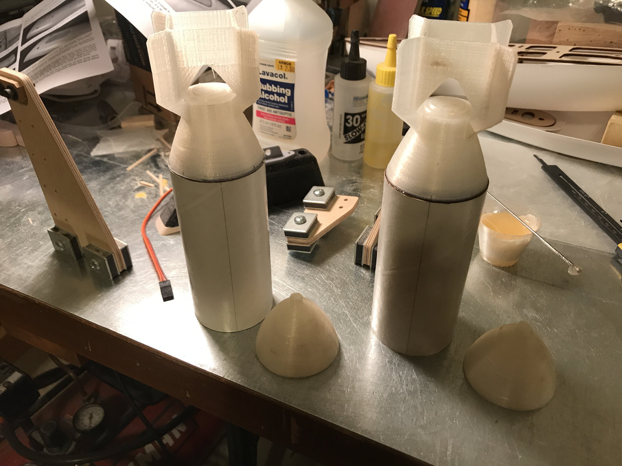
Tail cones epoxied in place. Could have stood them the other way and glued both ends on at the same time. Instructions lacked info on CG, so left the nose cones off. Little info found on the internet. Even looked for CG location on throwing darts. Found a site with a picture of a WWII 250lb bomb with features located at the midpoint of the cylinder, locating the CG and lifting points. Will replicate this CG point, adding weight to the nose cones.
Next entry, I should have some input regarding the drop tank assembly.
Re-formed the upper exhaust ducts. Drawings from one designer, cowling from another - the ducts didn't line up with the cowling parting lines correctly. Had to redo them. Next time, when using parts, drawings from multiple sources, will get all my parts before cutting anything.
Cardboard cylinders for dummy bombs, center lines drawn. Check length and perpendicularity before proceeding! One was perfect, the other needed some sanding to get it square and to same length as the other.
Wood mounts installed. Need a slot cut for the payload mounting plate. A screw at each end of the plate, into the wood, will hold it in place.
Plastic rings epoxied into each end. The nose and tail cones are glued to these rings.
Tail cones epoxied in place. Could have stood them the other way and glued both ends on at the same time. Instructions lacked info on CG, so left the nose cones off. Little info found on the internet. Even looked for CG location on throwing darts. Found a site with a picture of a WWII 250lb bomb with features located at the midpoint of the cylinder, locating the CG and lifting points. Will replicate this CG point, adding weight to the nose cones.
Next entry, I should have some input regarding the drop tank assembly.
02-13-2021, 06:30 PM
#279
Thread Starter
Progress on the Top-Flite Hellcat drop tank.
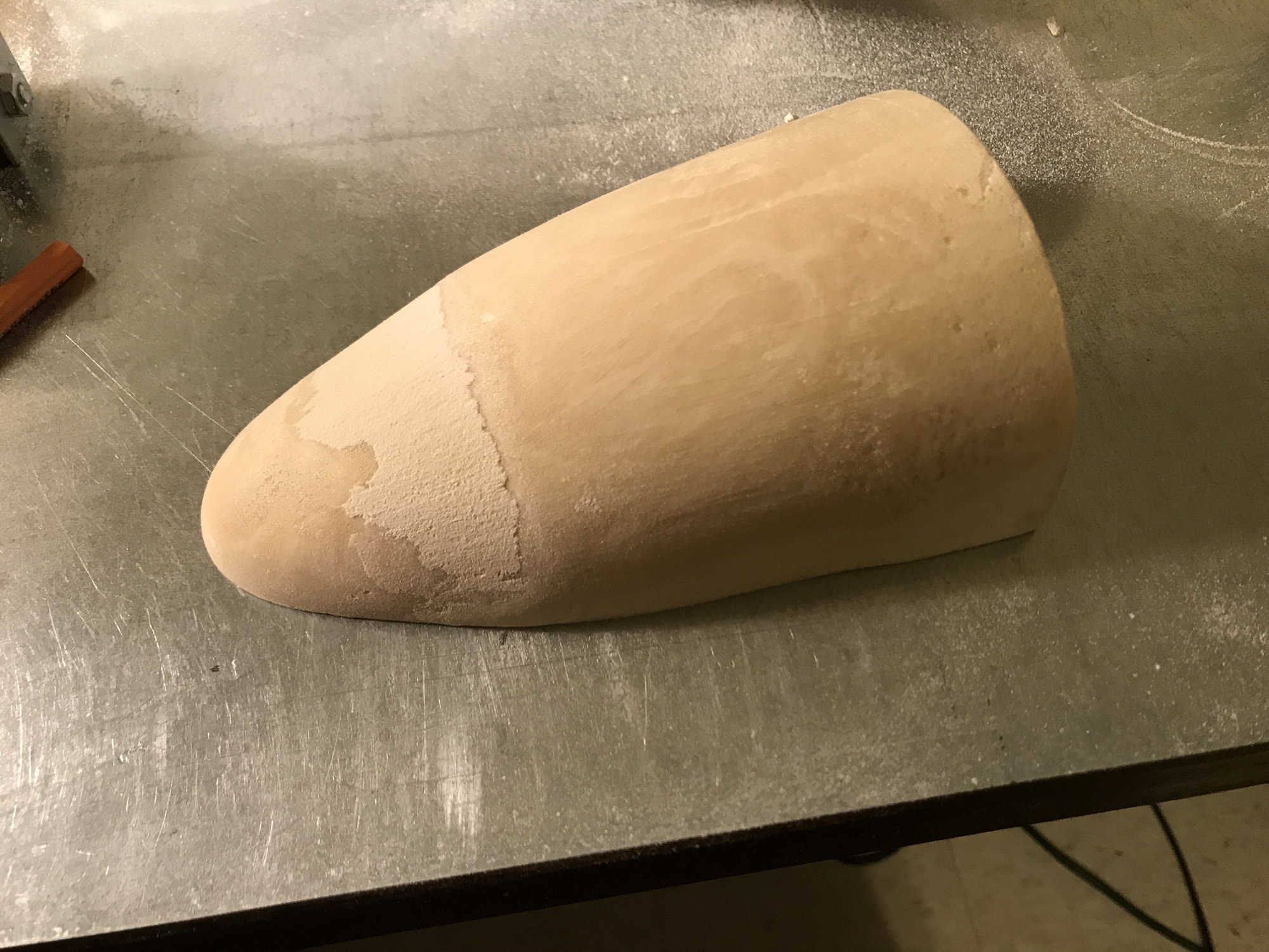
There are a couple closed foam 'plugs' for the nose of the drop tank. This one, for the top half of the tank, needed some filler. Also, needed to sand the flat side that faces the center of the tank, to ensure there was room for the frame to sit flush with the edge of the tank half.
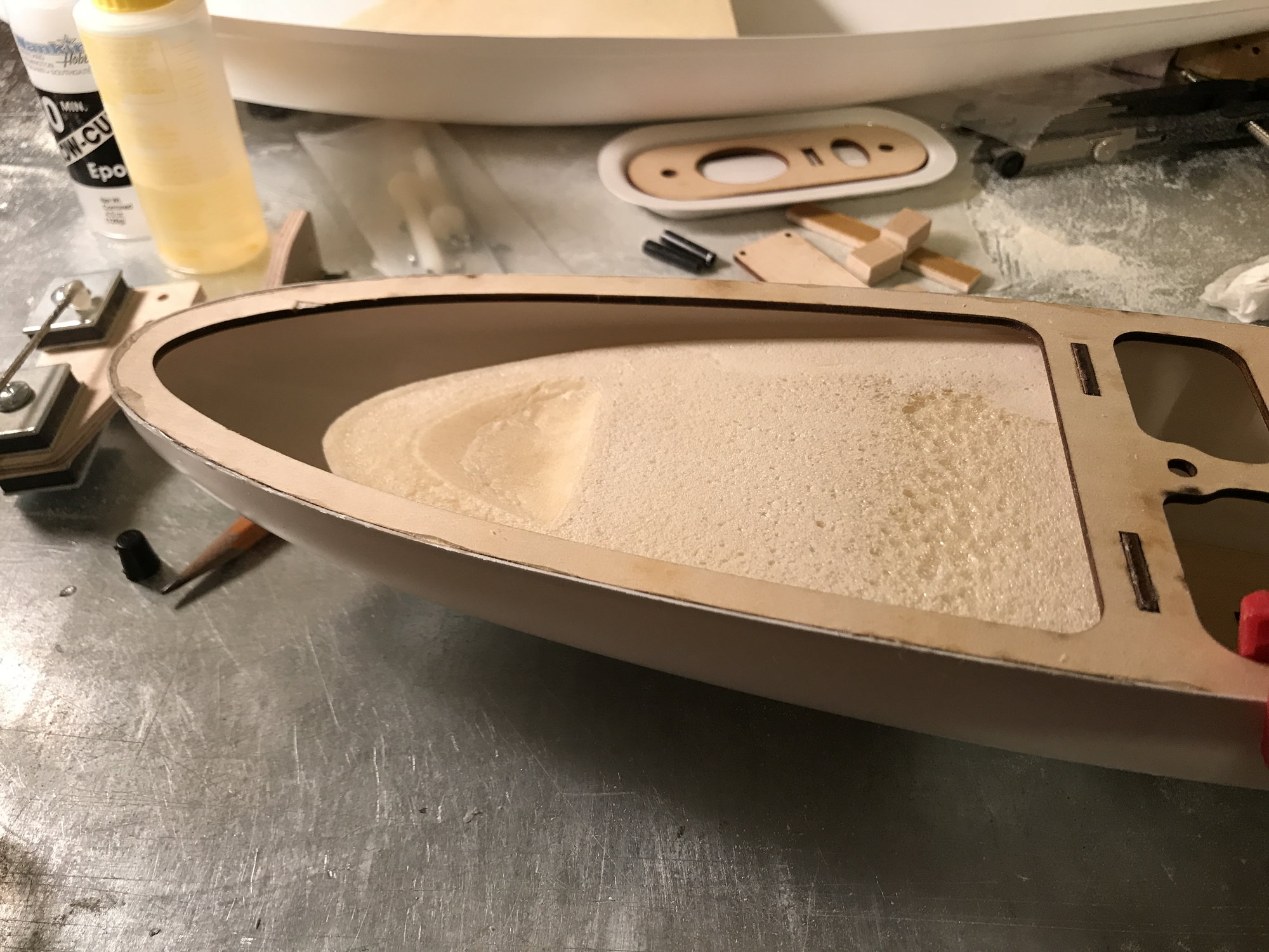
The tank is made of ABS - it's a bit floppy. I used 5 min. epoxy to glue the frame to the top half of the tank. Did this in 4 sections, holding each by hand: Nose to front frame brace, left side (top of pic); nose to front frame brace, right side (bottom of pic); frame brace to end of frame, right side; frame brace to end of frame, left side. Foam plug is loose.
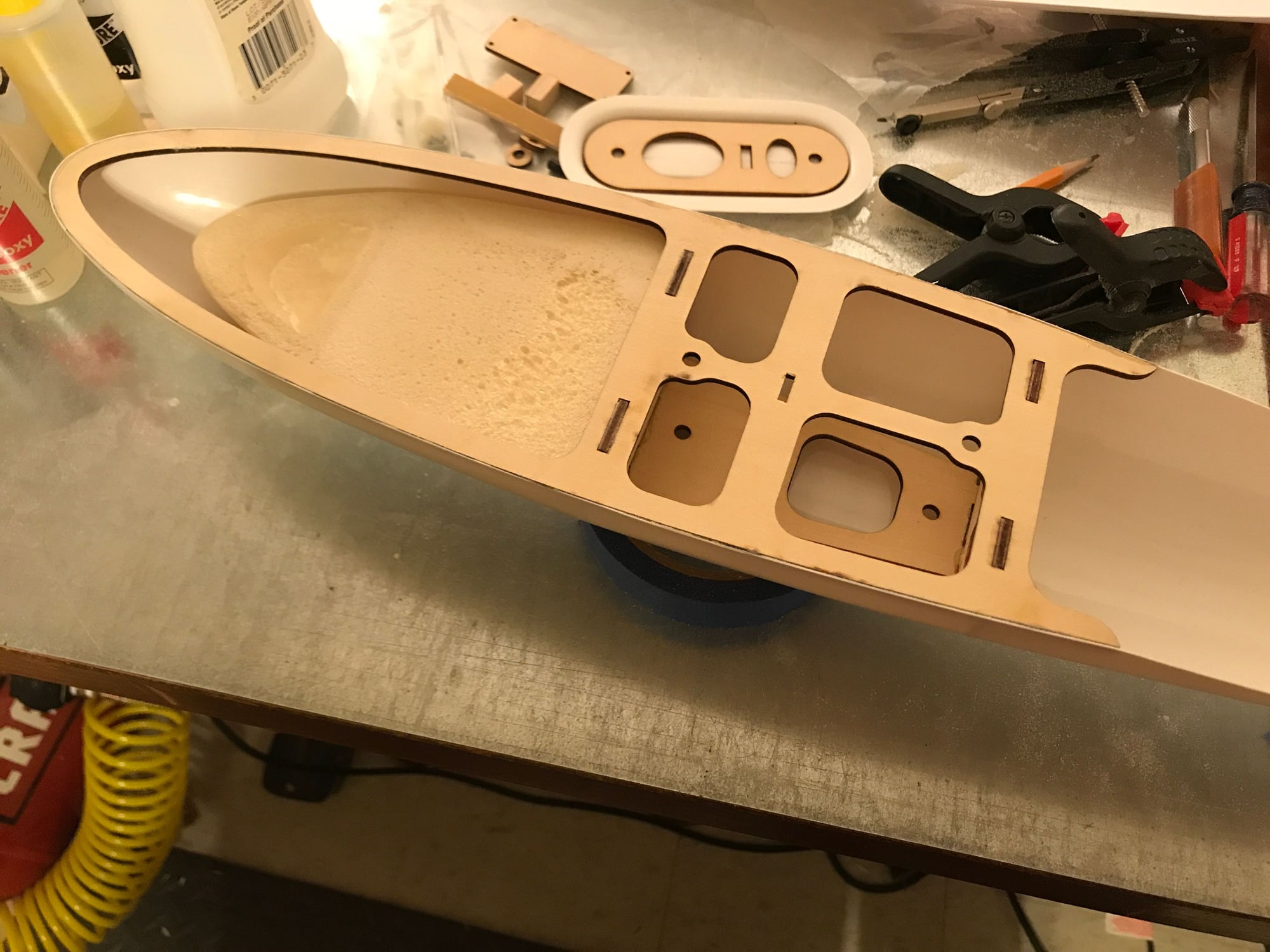
Frame glued in place, plug loose. Instructions have one glue the plug in place, first, leaving space for the frame; then, glue the frame in. I found this too awkward, as the ABS was so flexible. Trying to hold the plug in place, keeping a gap for the frame...just thought it too was to easy to end up with a misshaped tank. Drizzled thin 30min epoxy between the ABS and plug, spread it well, including between the frame and plug.
Once the epoxy is drizzled in and spread, pushed the plug forward and laid a bead of 5min epoxy to form a fillet between the plug and ABS - its secured.
Tank mount resting on guide pins on top of tank.
There are a couple closed foam 'plugs' for the nose of the drop tank. This one, for the top half of the tank, needed some filler. Also, needed to sand the flat side that faces the center of the tank, to ensure there was room for the frame to sit flush with the edge of the tank half.
The tank is made of ABS - it's a bit floppy. I used 5 min. epoxy to glue the frame to the top half of the tank. Did this in 4 sections, holding each by hand: Nose to front frame brace, left side (top of pic); nose to front frame brace, right side (bottom of pic); frame brace to end of frame, right side; frame brace to end of frame, left side. Foam plug is loose.
Frame glued in place, plug loose. Instructions have one glue the plug in place, first, leaving space for the frame; then, glue the frame in. I found this too awkward, as the ABS was so flexible. Trying to hold the plug in place, keeping a gap for the frame...just thought it too was to easy to end up with a misshaped tank. Drizzled thin 30min epoxy between the ABS and plug, spread it well, including between the frame and plug.
Once the epoxy is drizzled in and spread, pushed the plug forward and laid a bead of 5min epoxy to form a fillet between the plug and ABS - its secured.
Tank mount resting on guide pins on top of tank.
The following users liked this post:
CAPT John (02-14-2021)
02-14-2021, 08:16 AM
#280
Thread Starter
Just discovered that Top-Flite parts, kits are kaput. Finding discussions, now, on the internet, going back a couple years. Guess this happened when I wasn't looking. I best not damage the cowling or drop tank!
02-15-2021, 07:32 PM
#281
Thread Starter
I've been looking for a spare Top Flite Hellcat drop tank - not finding any. However, I did find this page where, half way down, is a picture of a tank someone has framed up from balsa: KSU Flyer's drop tank
Last edited by DaleCS; 02-15-2021 at 07:35 PM.
02-15-2021, 08:22 PM
#282

My Feedback: (60)
Join Date: Dec 2001
Location: Litchfield Park,
AZ
Posts: 7,677
Likes: 0
Received 25 Likes
on
23 Posts
I've got a new 3d printer on the way that may be just the ticket for drop tanks. Not quite big enough to do them all in one go but I could probably do them in 3 pieces. They could be made to key together for a strong and precise joint that would just need a little filler to be perfect. The printer uses resin and is high resolution so the finished surface is nearly perfect. I did a plug for a vacuum formed 1/6th scale drop tank some years back but it was just too large for my forming equipment. I sent the plug to a vac-forming service that offered them for a couple of months and then went out of business. Never did get my plug back!
02-17-2021, 05:55 PM
#283
Thread Starter
Chad - I could get you sketches, dims off the TF Hellcat tank. I don't know how many TF Hellcat owners are out there that may want to buy a replacement that could plug & play with the TF mount/release mech. I was thinking about documenting the design to some extent, should I ever need to rebuild/replace it. The internal framework will be 'close-enough' - should've traced the pieces before assembling, installing in the tank, but wasn't thinking about TF failing.
02-17-2021, 08:51 PM
#284
My Feedback: (60)
Join Date: Dec 2001
Location: Litchfield Park,
AZ
Posts: 7,677
Likes: 0
Received 25 Likes
on
23 Posts
Chad - I could get you sketches, dims off the TF Hellcat tank. I don't know how many TF Hellcat owners are out there that may want to buy a replacement that could plug & play with the TF mount/release mech. I was thinking about documenting the design to some extent, should I ever need to rebuild/replace it. The internal framework will be 'close-enough' - should've traced the pieces before assembling, installing in the tank, but wasn't thinking about TF failing.
Last edited by Chad Veich; 02-17-2021 at 08:53 PM.
02-20-2021, 06:16 PM
#285
Thread Starter
Sent pics of drawings to your CWVM email. Let me know if they came through OK and if they are useful, or not.
02-28-2021, 11:22 AM
#286
Thread Starter
Drawings off to Chad.
After getting most of the assembly done on the drop tank, I've decided to switch to an E-Flite payload release. Couple reasons for this: if dropped in flight, at low enough altitude, tank may slide on ground - I didn't like the idea of the release 'board' sticking out of the the tank, perpendicular to tank travel - this gets caught in the ground there's going to be damage; also, the Top-Flite release design only offers release via the servo. If something goes wrong, one must drop the belly pan to manually release the mech.
E-Flite payload release mech solves both problems. However, I may not ever drop this tank in flight - it's probably going to hit nose first and that will be the end of it. Thinking about a parachute... Wouldn't be scale, but if I have gear trouble, would be great to dump the tank and know that it won't be destroyed.
Any comments?
Also - found a spare Top-Flite F6F cowling in Australia - bought and shipping. It's insurance. I'd rather have a spare and never need it, vs. needing one and not having it. I do have a spare from another vendor, but making it fit would be a big project, though not impossible.
Release mounting plates installed. Need to balance, epoxy the nose pieces in place, then ready for finishing.
A bit more progress on the dummy devices:
03-01-2021, 10:57 AM
#287
My Feedback: (60)
Join Date: Dec 2001
Location: Litchfield Park,
AZ
Posts: 7,677
Likes: 0
Received 25 Likes
on
23 Posts
The new 3d printer arrived yesterday, very excited to get it set up and running. Still working on my shop renovation though and so it will probably be a couple of weeks before I have the time to play with it. Certainly you would not want to drop a 3d printed resin drop tank, no way it would survive. Maybe, just maybe, a tank 3d printed from nylon would be able to take the punishment. However, at 1/6th scale it would be a rather expensive drop tank. I cannot print in nylon so it would have to be done by one of the printing services and I imagine it would be multiple hundreds of dollars for a single tank. I think the best method, and one I have used in the past, would be to vacuum form the shells from very thin styrene and attach them to a framework made from Depron foam. The result is a very light weight tank that has some ability to twist and distort without breaking. Unfortunately my vacuum forming equipment is not large enough to do a tank of this size. But surely somebody out there could do it.
03-02-2021, 06:07 PM
#288
Thread Starter
Thanks for looking at it Chad. For now, my TF drop tank will be for display and not for dropping. That way, I won't lose or destroy it!
The TF cowling I found in Australia turned out to be a mirage - still on vendors website but out of stock in reality. I'll try to be careful with the one I've got.
The TF cowling I found in Australia turned out to be a mirage - still on vendors website but out of stock in reality. I'll try to be careful with the one I've got.
03-02-2021, 09:16 PM
#289
My Feedback: (60)
Join Date: Dec 2001
Location: Litchfield Park,
AZ
Posts: 7,677
Likes: 0
Received 25 Likes
on
23 Posts
https://precisioncutkits.com/product...n-f6f-hellcat/
03-03-2021, 07:20 PM
#290
Thread Starter
Per chance did you check out the Don Smith Hellcat cowl for size? Smith has a plan for a 1/6 scale Hellcat so it has to be pretty close, no?
https://precisioncutkits.com/product...n-f6f-hellcat/
https://precisioncutkits.com/product...n-f6f-hellcat/
Everyone making a 1/6 scale plane seems to come up with different dimensions and shapes.
12-27-2021, 11:41 AM
#292
Thread Starter
I'm back, retired, and with some time to work on the Hellcat. I need to complete the mounting of the drop tank to the belly-pan. I also want to develop a parachute system for it, as TF no longer makes this tank, and I'd had to destroy it. May not be historically accurate, but it isn't 1945, either. Perhaps an addition of a fin at the back, between the tank and the fuselage, like the original tank had, with room to stuff a parachute into it?
Merry Christmas and a Better New Year to everyone!
Merry Christmas and a Better New Year to everyone!
The following users liked this post:
SHANEC (12-28-2021)
12-29-2021, 04:45 AM
#293
My Feedback: (23)
My Hellcat is in my garage hanging. Took the JR stuff out of it since now I fly Jeti. I have it for sale with not to many takers. I still need to weather it some for more of a realistic look. I figured I�d let the next owner do it. It�s the first time in my life I am afraid to fly it! It was so much work that I am terrified in just the thought of flying it! Retirement is about two years for me. Enjoy it Dale, I can taste mine!
I hope you do lights on it!
I hope you do lights on it!
01-09-2022, 05:30 PM
#294
Thread Starter
My Hellcat is in my garage hanging. Took the JR stuff out of it since now I fly Jeti. I have it for sale with not to many takers. I still need to weather it some for more of a realistic look. I figured I�d let the next owner do it. It�s the first time in my life I am afraid to fly it! It was so much work that I am terrified in just the thought of flying it! Retirement is about two years for me. Enjoy it Dale, I can taste mine!
I hope you do lights on it!
I hope you do lights on it!
01-11-2022, 09:38 AM
#296
Thread Starter
I see it and the shipping notice. If not sold by mid-Spring, I'll check back, as I may have a trip to the SE states, including Florida - a friends and family tour. I need to contact some Florida cousins, confirm current locations. If any are close to Miramar, and if anyone in our club is interested, I could be a means of transport, though I expect the cowling and engine would need to be removed in order to fit in my Jeep GC. In the meantime, try to find a trusted expert to fly the plane with the instructions, "Keep the speed up and no stunts!"
02-08-2022, 04:00 PM
#297
Thread Starter
Resolved the drop tank installation design. As this belly tank kit is not longer available from TF, my design mods may not be so useful for others.
Here goes: I had some concerns with the 'out of the box' design: A piece of 'fiber' board with a piece of 4-40 wire through it to serve as the drop mech. I figured the fiber board was easy to damage (and once damaged, not easily repaired), and I didn't like having a servo buried in the belly pan, where I couldn't manually activate it to release the drop tank if something when wrong (would require some disassembly of the plane to access). As I had already chosen E-flite servos for the dummy bombs, I chose to use the same for the drop tank. Of course, I made this decision after having assembled most of the drop tank per the instructions...this made the change more difficult to implement!
I went through two design iterations. The first utilized a couple hard pieces of wood, cut and shaped to glue to the inside, plastic, curved surface of the tank, which the E-flite adapter could be screwed to. Easy to implement, but I wasn't happy, as I could envision the plastic failing under vibration. Also, I recognized that the original design had the 'fiber' board epoxied to the internal, wood framework. This framework was expected to carry the load, not the plastic skin of the tank.
So, the second iteration would utilize the wood framework to carry the load, and is shown in the following pictures.
7/16" dowel posts and a balsa box.
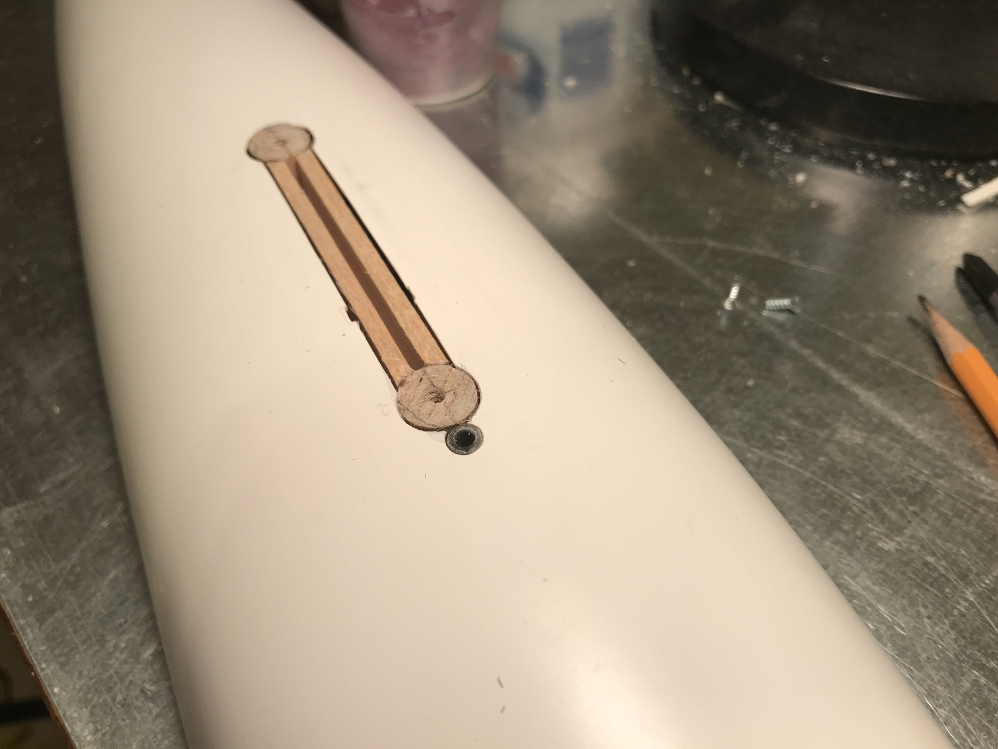
A few details from the original install design still visible (hole for carbon fiber dowel, notches alongside balsa 'box' where "fiber" board would have been glued in)
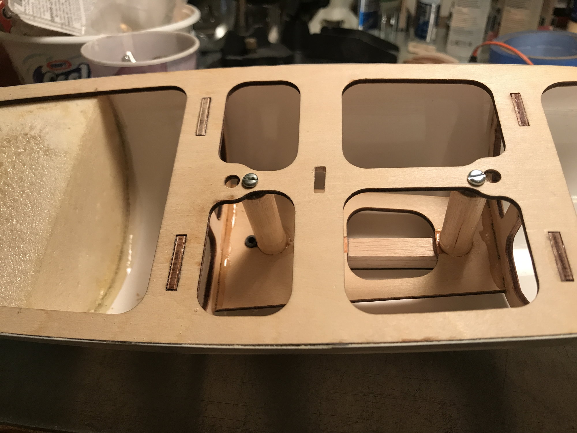
Bottom of dowels epoxied and screwed.
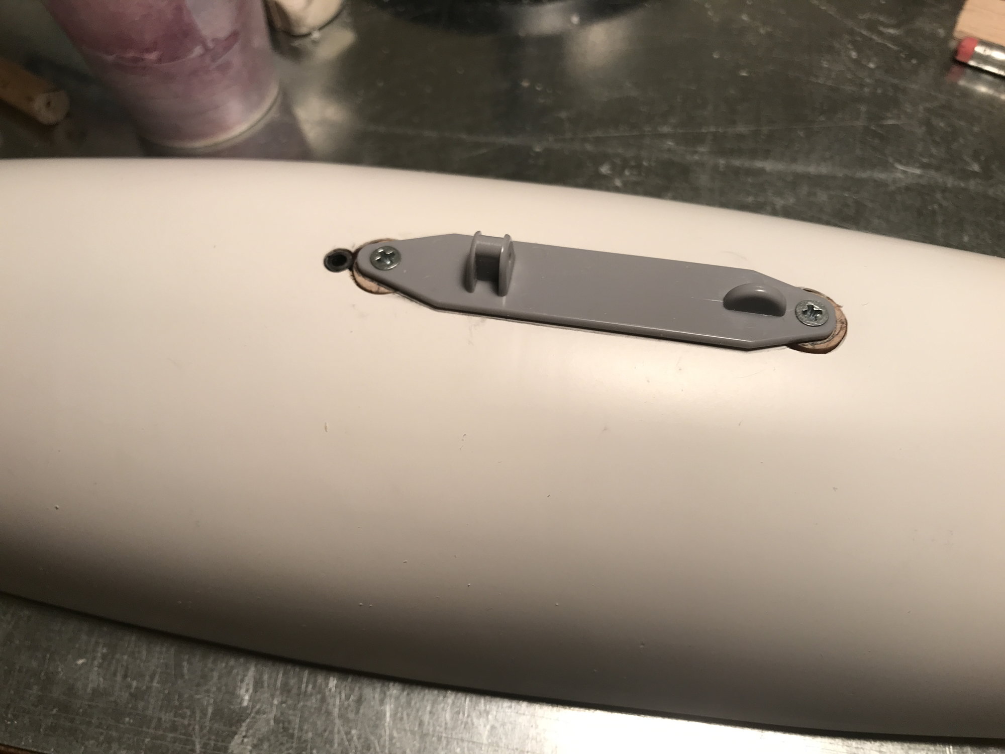
Drop adapter attached by screws into wood dowels. I may leave the gaps, carbon dowel opening as is, not sealing the gaps. These aren't seen when the tank is mounted to the aircraft, and they provide relief for expanding air - planning to paint plane and tank dark sea blue, which can get hot in the sun.
Next, I need to complete the modifications to the belly pan mount and complete installation to the belly pan.
Here goes: I had some concerns with the 'out of the box' design: A piece of 'fiber' board with a piece of 4-40 wire through it to serve as the drop mech. I figured the fiber board was easy to damage (and once damaged, not easily repaired), and I didn't like having a servo buried in the belly pan, where I couldn't manually activate it to release the drop tank if something when wrong (would require some disassembly of the plane to access). As I had already chosen E-flite servos for the dummy bombs, I chose to use the same for the drop tank. Of course, I made this decision after having assembled most of the drop tank per the instructions...this made the change more difficult to implement!
I went through two design iterations. The first utilized a couple hard pieces of wood, cut and shaped to glue to the inside, plastic, curved surface of the tank, which the E-flite adapter could be screwed to. Easy to implement, but I wasn't happy, as I could envision the plastic failing under vibration. Also, I recognized that the original design had the 'fiber' board epoxied to the internal, wood framework. This framework was expected to carry the load, not the plastic skin of the tank.
So, the second iteration would utilize the wood framework to carry the load, and is shown in the following pictures.
7/16" dowel posts and a balsa box.
A few details from the original install design still visible (hole for carbon fiber dowel, notches alongside balsa 'box' where "fiber" board would have been glued in)
Bottom of dowels epoxied and screwed.
Drop adapter attached by screws into wood dowels. I may leave the gaps, carbon dowel opening as is, not sealing the gaps. These aren't seen when the tank is mounted to the aircraft, and they provide relief for expanding air - planning to paint plane and tank dark sea blue, which can get hot in the sun.
Next, I need to complete the modifications to the belly pan mount and complete installation to the belly pan.
02-10-2022, 09:45 AM
#298
Thread Starter
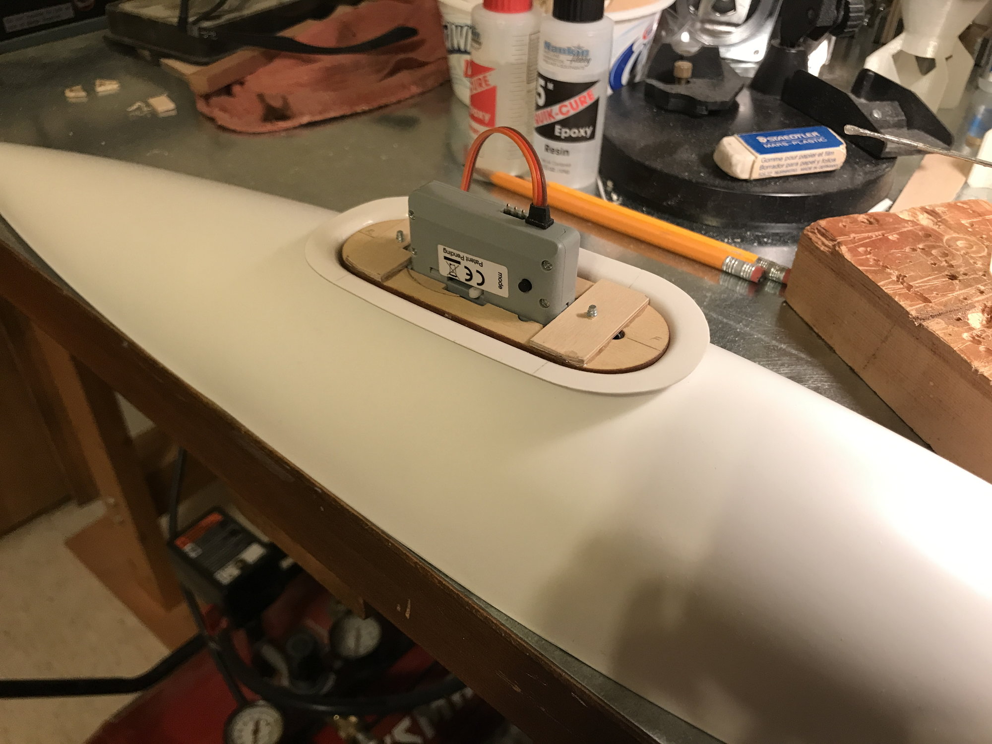
Drop servo installed to cradle. Next step, mount the cradle to the belly pan. There is a manual release slider on the side of the servo. My thought here is to attach a wire and run it out through the back of the cradle - pull and release!
That'll do, tank...that'll do.
That'll do, tank...that'll do.
09-02-2022, 12:36 PM
#299
Thread Starter
Well, retirement has been interesting! Issue developed in April - one from which I should fully recover, even without meds, but it's a long, slow process. Oh, and then there was COVID - my case wasn't bad, but it further delayed things. Just now getting back into some activities, including biking, pickle ball, house projects I fell behind on.... Taking things easy, but improving each week, now. Went to the club field last week after a long spell away, and it was like "Cheers" - where everybody knows your name!
Mounted the external, dummy, fuel tank to the belly pan, yesterday. In doing this, I added a means to manually actuate the servo drop release - just in case! This allows me to attach and detach the tank without power, a functioning servo and without having to remove the belly pan. Basically, I drilled a hole from the exterior of the pan mount towards the servo's release mech. Then inserted and epoxied a length of copper tubing in the hole. For now, I'm just running a length of fine fire from the servo release mech through copper tubing to the exterior, where I have it looped for grabbing with a pliers or small screw driver - pull and release!
Not sure that I'll fly with this dummy tank in place, and may not drop it unless a belly landing is required. Can't get replacement parts, so would hate to drop this tank and have it potentially damaged beyond repair. Have thought about building a means to drop it by parachute - not scale, for sure, but would keep the tank undamaged. This parachute idea has kept me from finishing the top/bottom half assembly of the tank, thinking that if I do the parachute idea, it would be easier to accomplish before final assembly. For now, I just want to get it to the prime and paint point, where I can perhaps ask for help to get it finished. I have taken way too long on this.
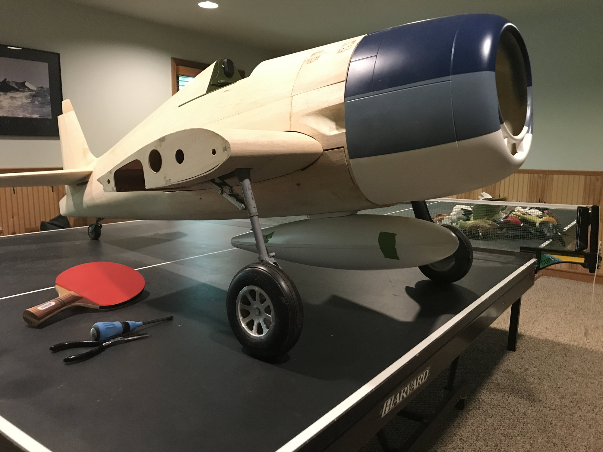
External dummy tank, mounted.
Manual release
Mounted the external, dummy, fuel tank to the belly pan, yesterday. In doing this, I added a means to manually actuate the servo drop release - just in case! This allows me to attach and detach the tank without power, a functioning servo and without having to remove the belly pan. Basically, I drilled a hole from the exterior of the pan mount towards the servo's release mech. Then inserted and epoxied a length of copper tubing in the hole. For now, I'm just running a length of fine fire from the servo release mech through copper tubing to the exterior, where I have it looped for grabbing with a pliers or small screw driver - pull and release!
Not sure that I'll fly with this dummy tank in place, and may not drop it unless a belly landing is required. Can't get replacement parts, so would hate to drop this tank and have it potentially damaged beyond repair. Have thought about building a means to drop it by parachute - not scale, for sure, but would keep the tank undamaged. This parachute idea has kept me from finishing the top/bottom half assembly of the tank, thinking that if I do the parachute idea, it would be easier to accomplish before final assembly. For now, I just want to get it to the prime and paint point, where I can perhaps ask for help to get it finished. I have taken way too long on this.
External dummy tank, mounted.
Manual release