


Ziroli 1/6 Hellcat Build
 12-26-2017, 01:11 PM
#176

Thread Starter
Tail control surface covered with Solartex, color "Linen." Why Linen? Well, if paint wears or gets chip, figured Linen would give it an authentic look. This is my first time working with Solartex - I'm very happy with its toughness, shrink rate and ability to form around wing and rudder tips. Also, having a fabric quality to it, one doesn't need to get extremely fussy with the balsa sanding.
Trim tabs were aluminum covered, so I plan to glass, prime and paint them - no Solartex.
From previous posts, one can see a third hinge in each elevator, inboard from those that one can still see in this picture. I don't know if the Hellcat had these, but from pictures, once can't see them if they are used. I've managed to hide them quite well. If one forces the elevator down farther, the hinge slot for them will eventually appear. At +/- 1 inch of throw, the slot won't be seen.
Now, torn between mounting the stab/fin, or covering the ailerons and outboard flaps - which should I do next?
 01-02-2018, 08:06 PM
#178

My Feedback: (60)
Join Date: Dec 2001
Location: Litchfield Park,
AZ
Posts: 7,677
Likes: 0
Received 25 Likes
on
23 Posts
Beautiful work Dale. Getting ready to have hip replacement surgery soon which I hope will help to boost my energy levels back up substantially. As soon as I can get my head above water I will tackle the cockpit stuff for our birds. So keep up the pace but not too fast! 
Oh, and happy new year too!
Oh, and happy new year too!
01-07-2018, 07:35 PM
#179
Thread Starter
Hi Chad - expect your surgery will go well and you'll feel much better. Have had a number of people around me getting hips or knees replaced. All are doing better. One woman, after getting her second hip done, went to Slovenia and Italy on vacation within a couple months after surgery. Expect no less for you.
Thanks for the kind comments about my 'cat No worries about being too fast....I think I missed that opportunity long ago.
Right flaps fitted and right outer flap covered. Noted that when deploying flaps, with the offset hinges, the leading edges of the two flaps hit each other at W6. This happens because the inner and outer flaps are rotating in different planes due to the dihedral angle. At the leading edge, inboard rib of the outer panel, sanded away material so that when flaps are deployed, I have a bout a 1mm of clearance between the inner and outer flaps. This can be seen in the third picture - the inside edge of the other flap is straight, then makes a slight direction change about a half inch or so from the leading edge.
Have the left flaps to do, next.
Now that the fabric covered control surfaces are almost done, can see why some just go with the balsa sheeted design - at these small sizes, the fabric shrinks with no sag - can't really see the presence of ribs unless one holds them up to a light. and once painted, won't see them at all. Expect that I won't be able to skip pinking tape. Looking pictures over, it appears that the Hellcat used a straight, unpinked tape. This will making cutting tape strips from Solartex easy, and cheap. Will get the left flaps done, then try the taping - hopefully, it will look good.
01-08-2018, 12:12 AM
#180
My Feedback: (60)
Join Date: Dec 2001
Location: Litchfield Park,
AZ
Posts: 7,677
Likes: 0
Received 25 Likes
on
23 Posts
Regarding fabric, I'm one of those that does not bother and just simulates it on a sheeted surface. I've looked at a lot of restored warbirds and even on the real deal the fabric is so tight as not to have much discernible sag. Most times the only thing that reveals it is fabric is the presence of stitching and tapes. I'm pretty sure the Hellcat has pinked tapes but at this scale they would be so small as to be invisible. You would have to exaggerate them considerably if you wanted a visible pinked edge. I just did the elevators on a 1:3.7 scale Macchi and even at that size I exaggerated them a bit for appearance sake. I developed a new technique this time around that I really like and consists of nothing but glue and primer.
01-08-2018, 08:09 PM
#181
Thread Starter
Hi Chad - regarding hips and knees, I see this is not your first rodeo. I've heard that hips are a much easier recovery path. Your craft work, and that of several others, here, is just in another league. If I get mine flying this year, have a few more details than the average kit, and have learned a few things, I'll count myself lucky.
I found this one picture showing the elevator. Resolution isn't great - looks like the tape parallel to the airstream is straight. Zooming in, the tape running perpendicular to the airstream, about 1/3 the way back from the elevator's leading edge, looks pinked. Maybe only on the rear edge:

Can also see a bit of fabric sag between some, but not al of the ribs. I may try to simulate this - put some weights on the fabric and heat it with my heat gun.
I found this one picture showing the elevator. Resolution isn't great - looks like the tape parallel to the airstream is straight. Zooming in, the tape running perpendicular to the airstream, about 1/3 the way back from the elevator's leading edge, looks pinked. Maybe only on the rear edge:
Can also see a bit of fabric sag between some, but not al of the ribs. I may try to simulate this - put some weights on the fabric and heat it with my heat gun.
01-08-2018, 11:13 PM
#182
My Feedback: (60)
Join Date: Dec 2001
Location: Litchfield Park,
AZ
Posts: 7,677
Likes: 0
Received 25 Likes
on
23 Posts
I found this one picture showing the elevator. Resolution isn't great - looks like the tape parallel to the airstream is straight. Zooming in, the tape running perpendicular to the airstream, about 1/3 the way back from the elevator's leading edge, looks pinked. Maybe only on the rear edge:
Attachment 2250480
Attachment 2250480
I will attempt to fake the apparent sag to some extent with some careful pre and post shading with an airbrush. It is more obvious on a glossy finish and, of course, in certain lighting conditions.
Last edited by Chad Veich; 01-08-2018 at 11:15 PM.
01-09-2018, 07:58 PM
#183
Thread Starter
Chad -
- We might argue the percentages on skill vs. patience, but this is all for fun - so, no arguing. Another factor might be tools. Your stitch glue guide - is that something you made up? Looks like thin strip brass with slots cut at regular intervals. I don't have the gear to make such a piece. Did find a method on YouTube that I can replicate:
- Regarding pinking, starting to think they used whatever they could get. Your last picture is quite clear - very fine pinking on all tapes. Have read where some use the blade from tin foil or wax paper box to cut fine pinks. Will try some experiments.
High-res shots welcomed. Do you have Dropbox?
- We might argue the percentages on skill vs. patience, but this is all for fun - so, no arguing.
Another factor might be tools. Your stitch glue guide - is that something you made up? Looks like thin strip brass with slots cut at regular intervals. I don't have the gear to make such a piece. Did find a method on YouTube that I can replicate:
High-res shots welcomed. Do you have Dropbox?
01-09-2018, 09:20 PM
#184
My Feedback: (60)
Join Date: Dec 2001
Location: Litchfield Park,
AZ
Posts: 7,677
Likes: 0
Received 25 Likes
on
23 Posts
 Shoot me an email and I will be glad to make some up for you to whatever specs you need. It really does make putting on the stitches a very simple process.
Yes indeed, I will upload the pics and send you the link as soon as I am able.
01-11-2018, 05:30 PM
#185
Thread Starter
Chad - got the pictures - thank you, these will be very helpful, though it might give me an excuse to not got to Kalamazoo Air Zoo... No, will still have to get out there.
I'll try some of my experiments - if they don't go well or I run out of time, will likely be contacting you.
I'll try some of my experiments - if they don't go well or I run out of time, will likely be contacting you.
01-20-2018, 06:58 PM
#187
Thread Starter
Ok - this looks like some past pictures - but it's different: Stab squared up to wing and fuse - installed! Looking, next, to get the elevator servos hooked up and their control rod supports in place, then vertical fin and tail piece.
02-23-2018, 04:36 PM
#188
Thread Starter
Took a break, a winter vacation, starting tax return.... - Now, back to the plane for a bit.
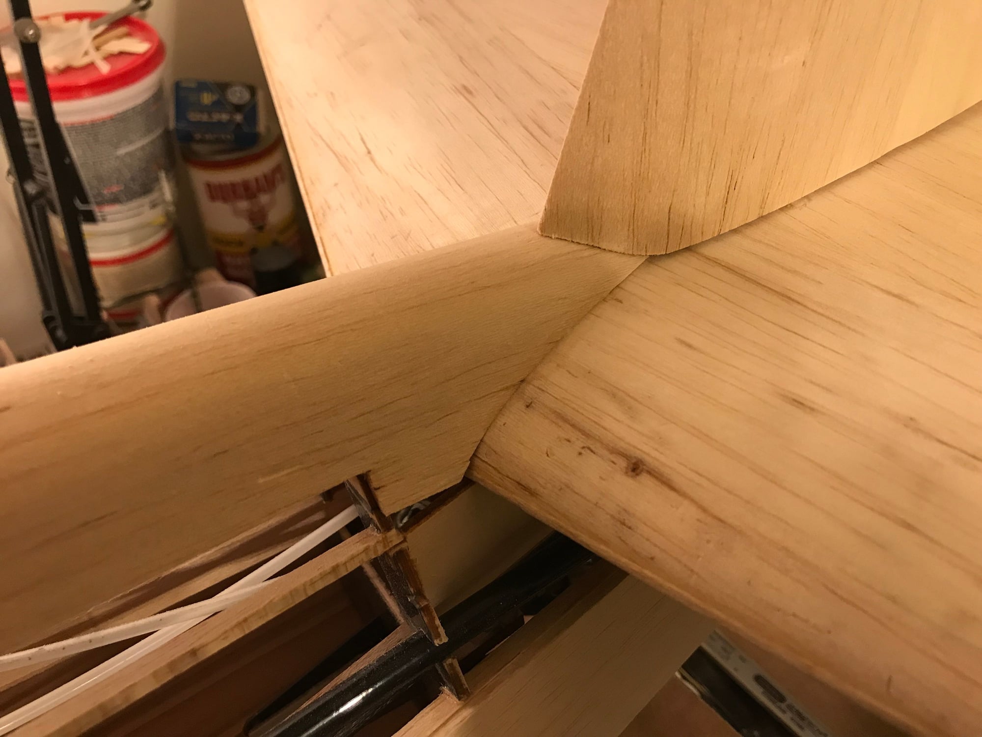
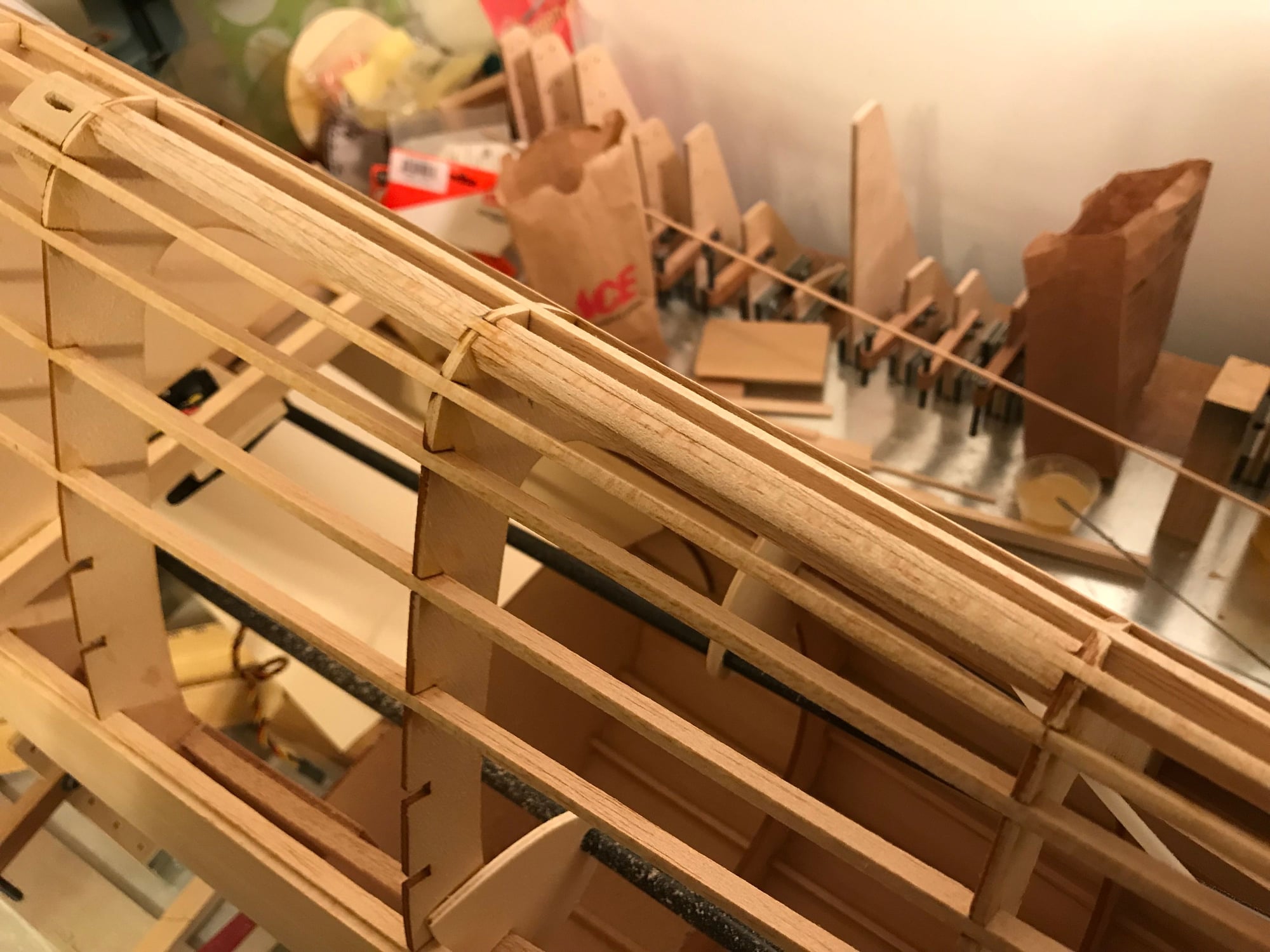
Supports for elevator control (flex) rods installed. Not exciting, but must be done. Supported rods just from the sides of the fuse. This leaves an opening for the pull-pull wires on rudder and tail wheel to pass through, unhindered.
Supports for elevator control (flex) rods installed. Not exciting, but must be done. Supported rods just from the sides of the fuse. This leaves an opening for the pull-pull wires on rudder and tail wheel to pass through, unhindered.
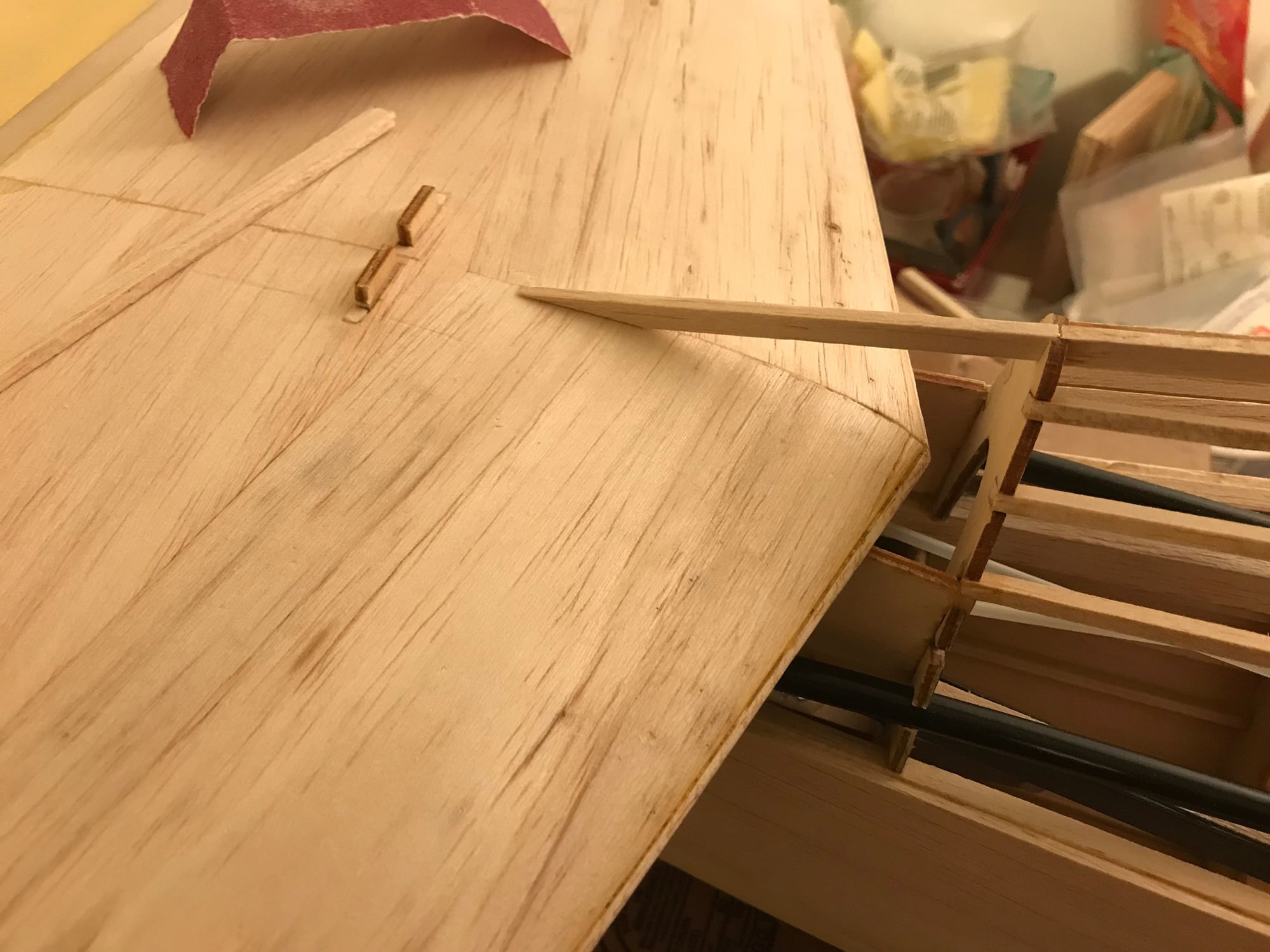
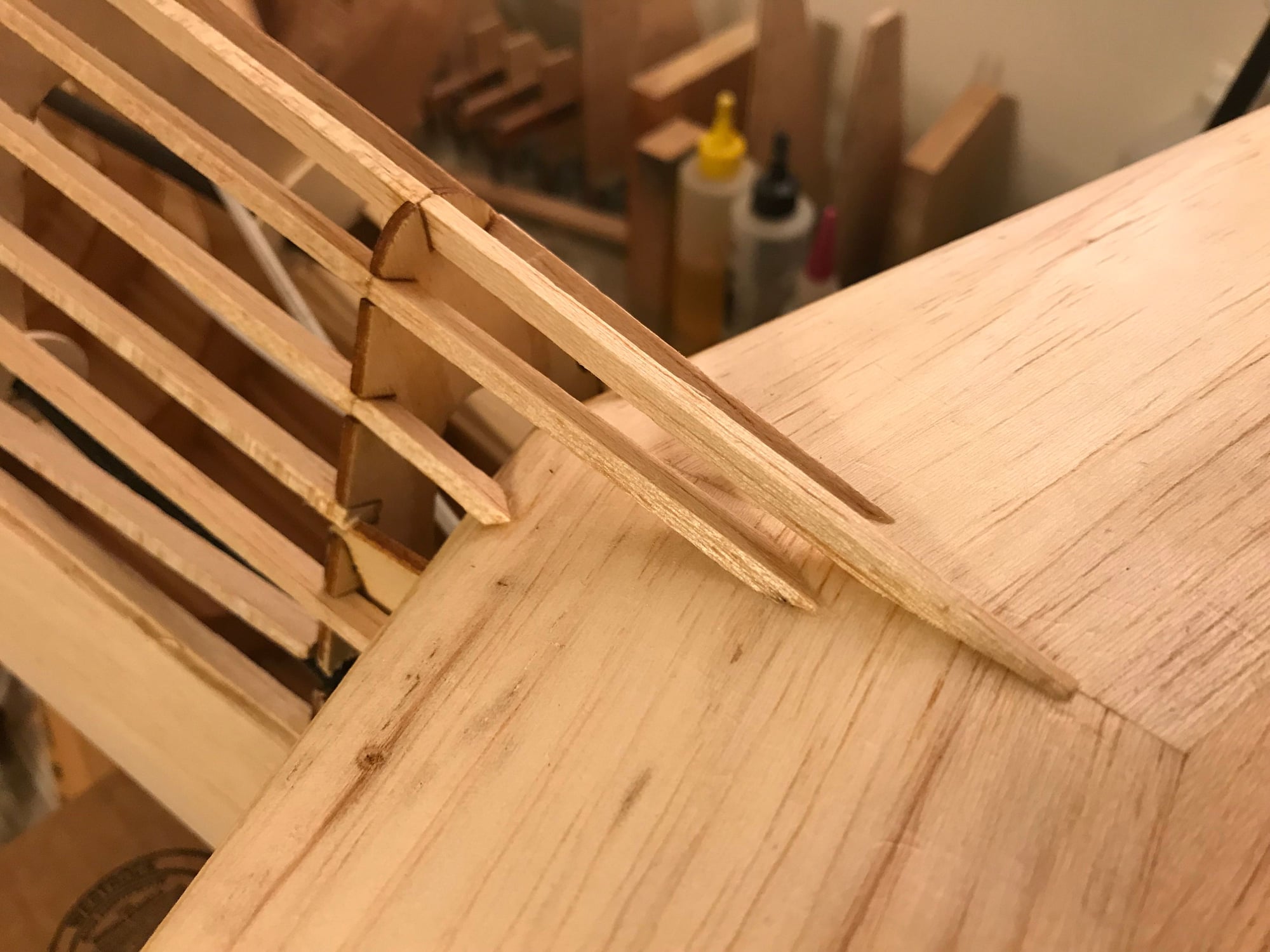
- First picture shows supports at F10, where I also notched F10, partially running the flex rod outer tubes through the former. This took a bend out of the tubes, allowing them to run straight at the servos.
- Second picture shows supports at F8, clamped while epoxy sets
- Third picture shows mounting blocks on bottom of cockpit floor at F5
 02-23-2018, 08:24 PM
#190
Thread Starter
Sullivan #517 (36") Black/Gold 4-40, on package. Website says 'high strength' - looks like I've got the right ones.
Expect to use Dubro 4-40 #518 pull-pull system on rudder and tail wheel. Used this successfully on my Byron F6F.
03-22-2018, 06:59 PM
#191
Thread Starter
Hello, back in town.
Trying to upload pictures, I see that there's a new method in this forum. Good news: I like the drag and drop feature. Bad news: If there's a way to resize pictures, the method is not intuitive - has anyone figured this out?
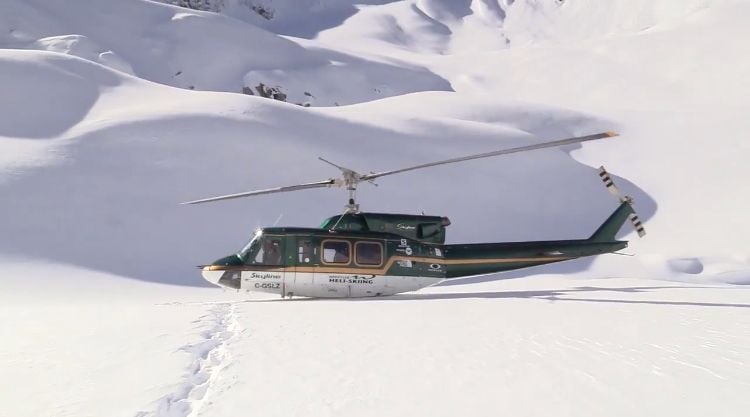
First picture was my ride for a day out in British Columbia, a Bell 212, the commercial version of the Huey. Not RC, but too fun not to mention.
Second picture - starting to frame up the fuse above the horizontal stabilizer. Prints are a bit vague, here. Also, I'm not finding much in way of instructions or pictures on line. Did see one example where h-stab was slid in after fin was assembled to fuse; another example showed someone had practically finished their plane without finishing this space above the h-stab - appears they were stuck, too, on how to finish this area and so they proceeded to glass and prime, while trying to figure out what to do.
Any suggestions?
In the meantime, my balsa block carving skills aren't great. Figured it would be easiest to extend the stringers back to the h-stab top surface, and then sheet the area same as the rest of the fuse. Only one stringer done - only just decided, tonight, to quit researching and go with my idea.
Bell 212
Framing fuse above horizontal stabilizer
Trying to upload pictures, I see that there's a new method in this forum. Good news: I like the drag and drop feature. Bad news: If there's a way to resize pictures, the method is not intuitive - has anyone figured this out?
First picture was my ride for a day out in British Columbia, a Bell 212, the commercial version of the Huey. Not RC, but too fun not to mention.
Second picture - starting to frame up the fuse above the horizontal stabilizer. Prints are a bit vague, here. Also, I'm not finding much in way of instructions or pictures on line. Did see one example where h-stab was slid in after fin was assembled to fuse; another example showed someone had practically finished their plane without finishing this space above the h-stab - appears they were stuck, too, on how to finish this area and so they proceeded to glass and prime, while trying to figure out what to do.
Any suggestions?
In the meantime, my balsa block carving skills aren't great. Figured it would be easiest to extend the stringers back to the h-stab top surface, and then sheet the area same as the rest of the fuse. Only one stringer done - only just decided, tonight, to quit researching and go with my idea.
Bell 212
Framing fuse above horizontal stabilizer
 03-30-2018, 01:34 PM
#194
Thread Starter
Thank you for the kind comment, Chic.
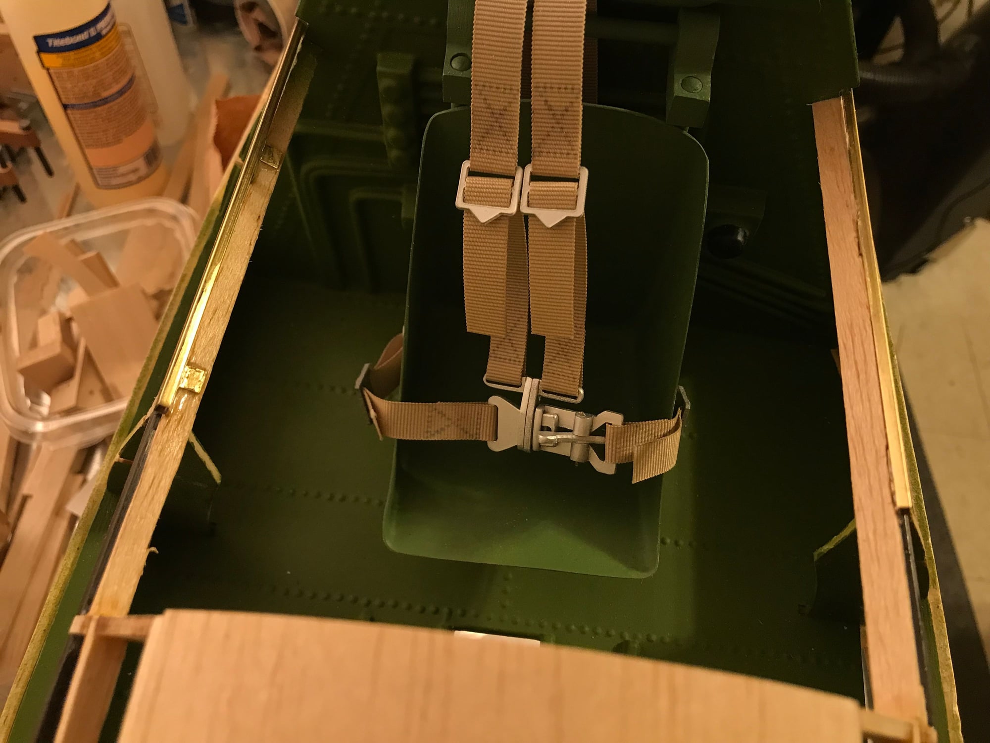
I've got the rear, short 'turtle deck' fitted and glued in place, and have sanded the vertical fin bottom to match the turtle deck. The deck is formed from a single piece of 1/8" sheet, using water with a bit of ammonia added to soften the wood. Did the forming in two steps, increasing the bend in steps, to avoid splitting. This should be stronger and lighter than carving/sanding a balsa block to fit the space above the elevator.
Next, I want to finish installation of the vertical fin and the remainder of the turtle deck. Will again use a single sheet of 1/8" softened and formed to fit. Due to my slow build rate, and wanting to see this fly at our September Giant Scale Fly-in, I may drop the lights I had planned, but still put the mounting blocks in - maybe add the lights next winter. Also, I found another source for 1/6 scale 50 cal wing barrels - IFlyTalies has some DIY to fully finished options in 1/8 through 1/2 scale.(IFlyTailies-scalegunsordnance). I've sent a question, today, asking if one can fit LEDs to these to simulate firing. I won a electronic firing simulator from Electro-Dynamics in a raffle some time ago, and would like to put it to use.
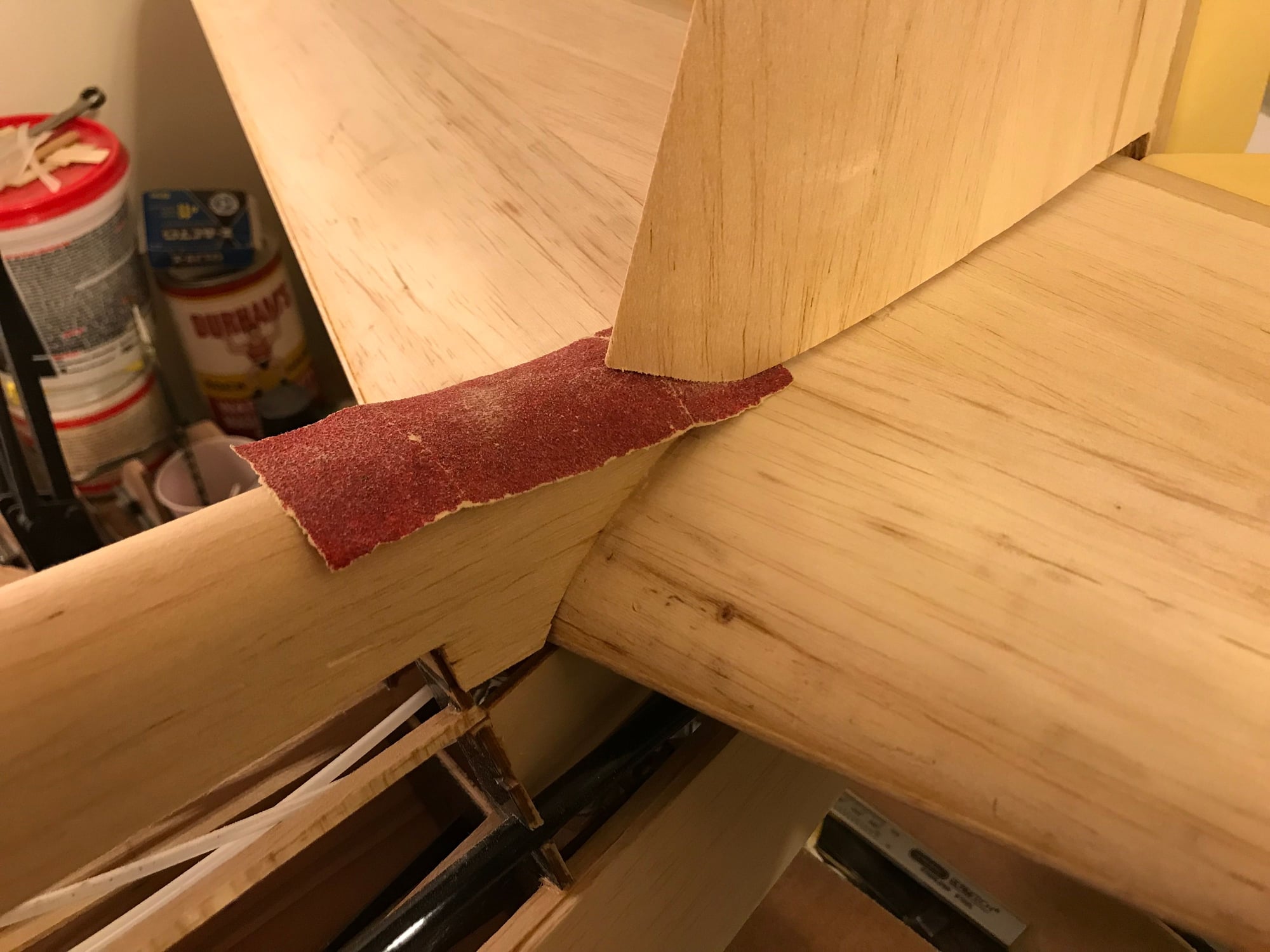
Turtle deck in place. Slicing sandpaper back and forth the remove excess fin sheeting.
Fin sand to fit turtle deck.
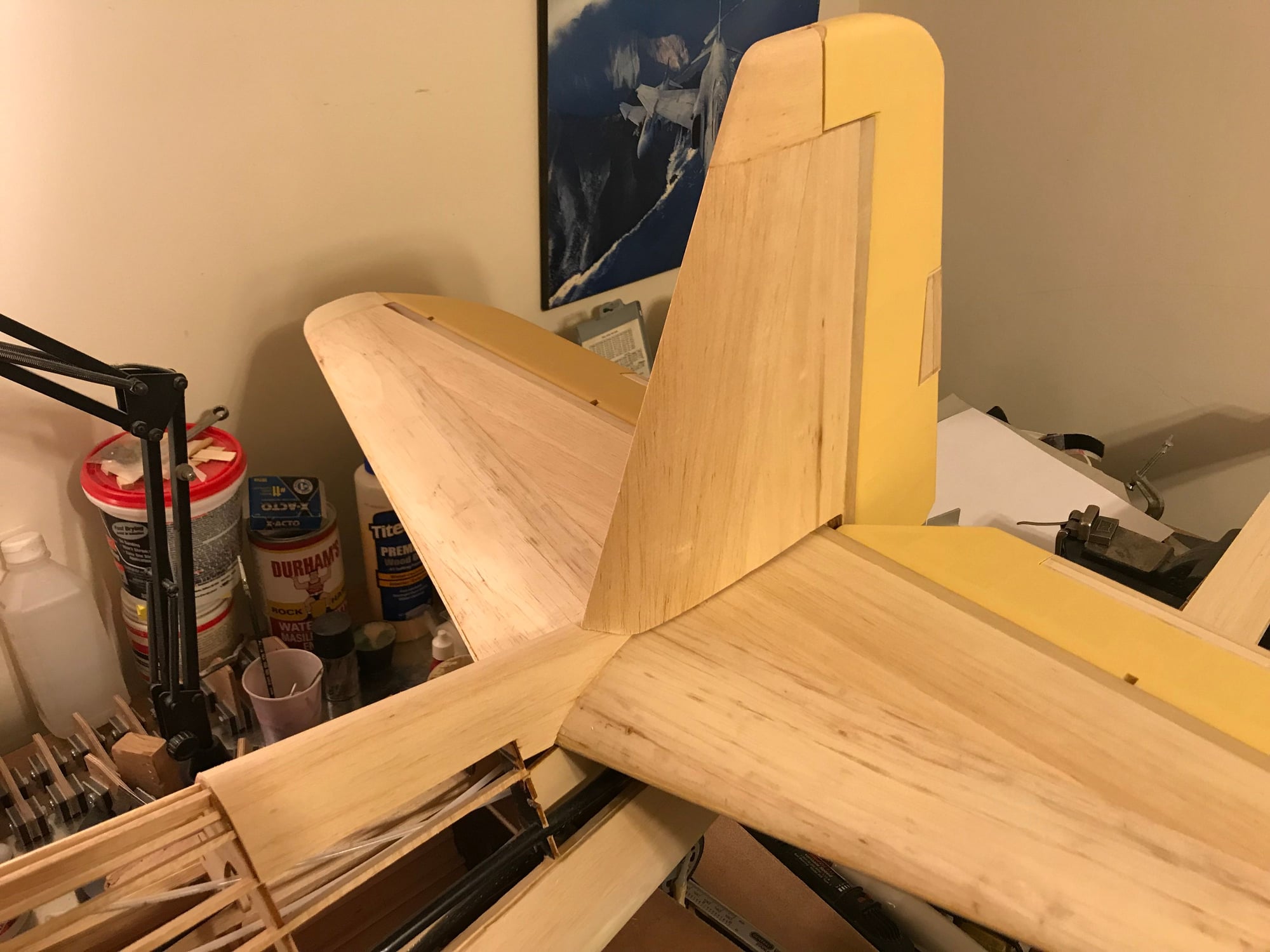
Fin ready for mounting to fuse.
I've got the rear, short 'turtle deck' fitted and glued in place, and have sanded the vertical fin bottom to match the turtle deck. The deck is formed from a single piece of 1/8" sheet, using water with a bit of ammonia added to soften the wood. Did the forming in two steps, increasing the bend in steps, to avoid splitting. This should be stronger and lighter than carving/sanding a balsa block to fit the space above the elevator.
Next, I want to finish installation of the vertical fin and the remainder of the turtle deck. Will again use a single sheet of 1/8" softened and formed to fit. Due to my slow build rate, and wanting to see this fly at our September Giant Scale Fly-in, I may drop the lights I had planned, but still put the mounting blocks in - maybe add the lights next winter. Also, I found another source for 1/6 scale 50 cal wing barrels - IFlyTalies has some DIY to fully finished options in 1/8 through 1/2 scale.(IFlyTailies-scalegunsordnance). I've sent a question, today, asking if one can fit LEDs to these to simulate firing. I won a electronic firing simulator from Electro-Dynamics in a raffle some time ago, and would like to put it to use.
Turtle deck in place. Slicing sandpaper back and forth the remove excess fin sheeting.
Fin sand to fit turtle deck.
Fin ready for mounting to fuse.
04-01-2018, 03:53 PM
#195

Awesome work, when done you will really have a special plane. After the maiden, you will want to enjoy a cold beer and think about the awesome project! My maiden day.....I am very glad it is over with! I look forward to the phase 2 of finishes and accessories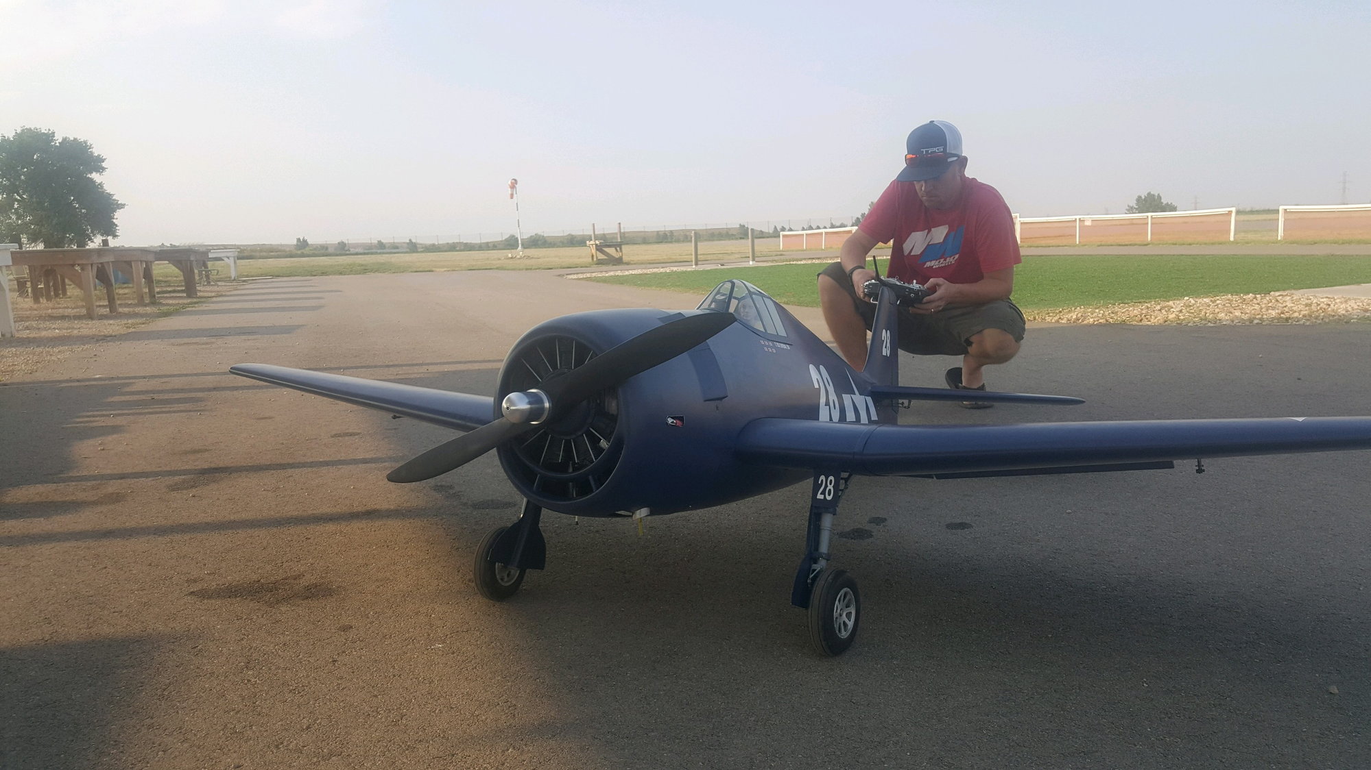
04-01-2018, 05:35 PM
#196
Thread Starter
Thanks for the comments, Show871. You Hellcat looks great. A post-maiden flight beer sounds like a good way to toast success.
I've got the turtle deck completed from cockpit to fin, with the cutout for the radio mast completed. I made the turtle deck in two pieces, as I didn't think I could successfully do the forming, fitting and gluing in one go. Having do it, now, I would attempt to do this as one piece on the next bird.
Rolling the 1/8 sheet
Added width to top stringers for nav light installation.
Sheet glued to stringers and first two formers behinc cockpit

Done!
I've got the turtle deck completed from cockpit to fin, with the cutout for the radio mast completed. I made the turtle deck in two pieces, as I didn't think I could successfully do the forming, fitting and gluing in one go. Having do it, now, I would attempt to do this as one piece on the next bird.
- First picture: I've soaked the sheet with water containing a bit of ammonia, rolling it into a u-shape and clamping overnight to dry.
- Second picture: I may install dorsal nav/signal lights - so I've tripled the width of the dorsal stringer to accept mounting holes for the lights
- Third picture: The dorsal line is not a straight shot from cockpit to fin - there's a bit of a curve between the 3 formers behind the cockpit; therefore, I glued my u-shaped sheet to the stringers and two forms behind the cockpit and let it set overnight. The next day, I soaked the sheet over the third former with the water/ammonia mix and slowly bent the sheet down to meet the rest of the formers.
- Fourth picture - Done, including the cutout for the radio mast
Rolling the 1/8 sheet
Added width to top stringers for nav light installation.
Sheet glued to stringers and first two formers behinc cockpit
Done!
04-05-2018, 06:25 PM
#197
Thread Starter
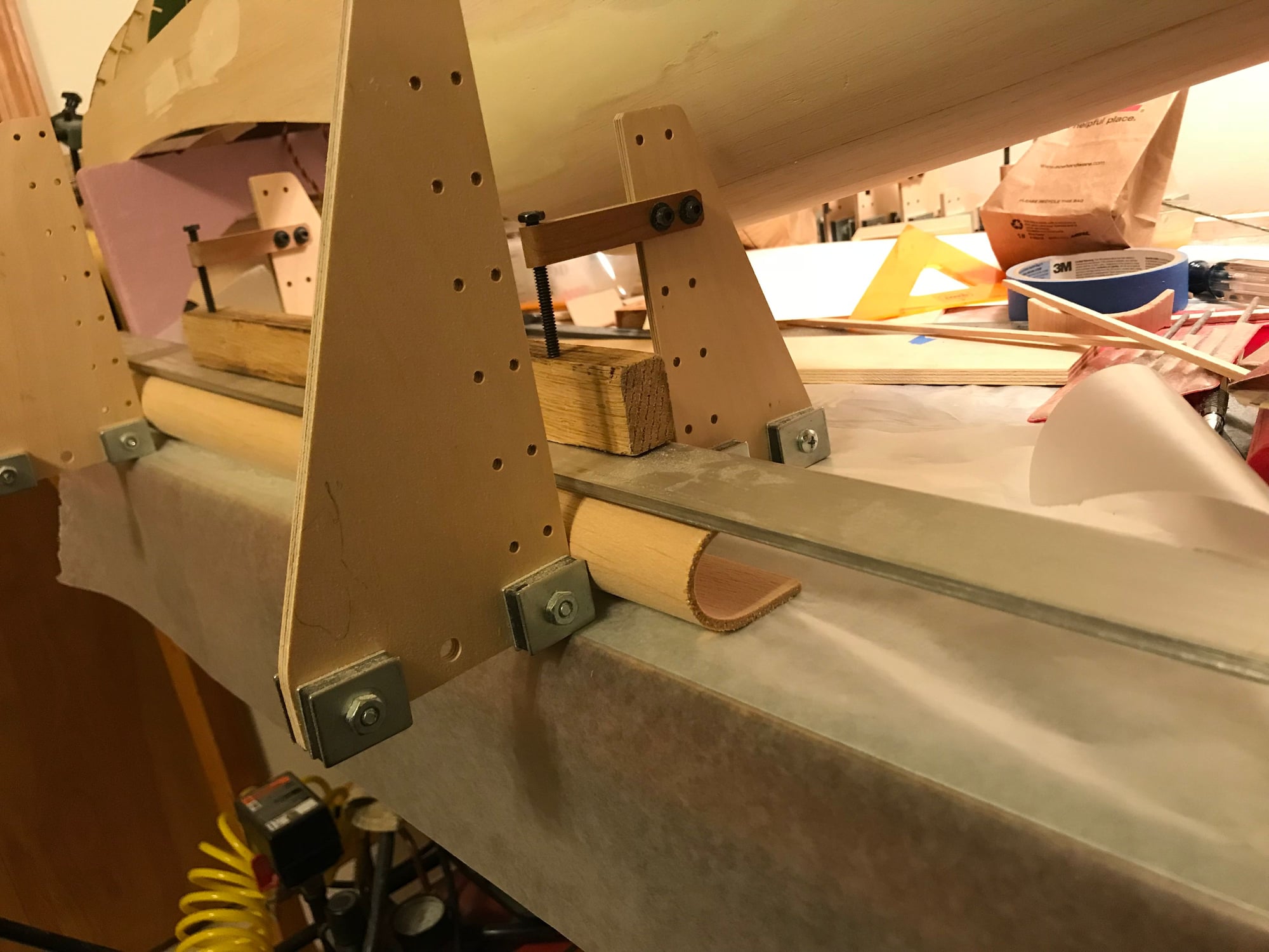
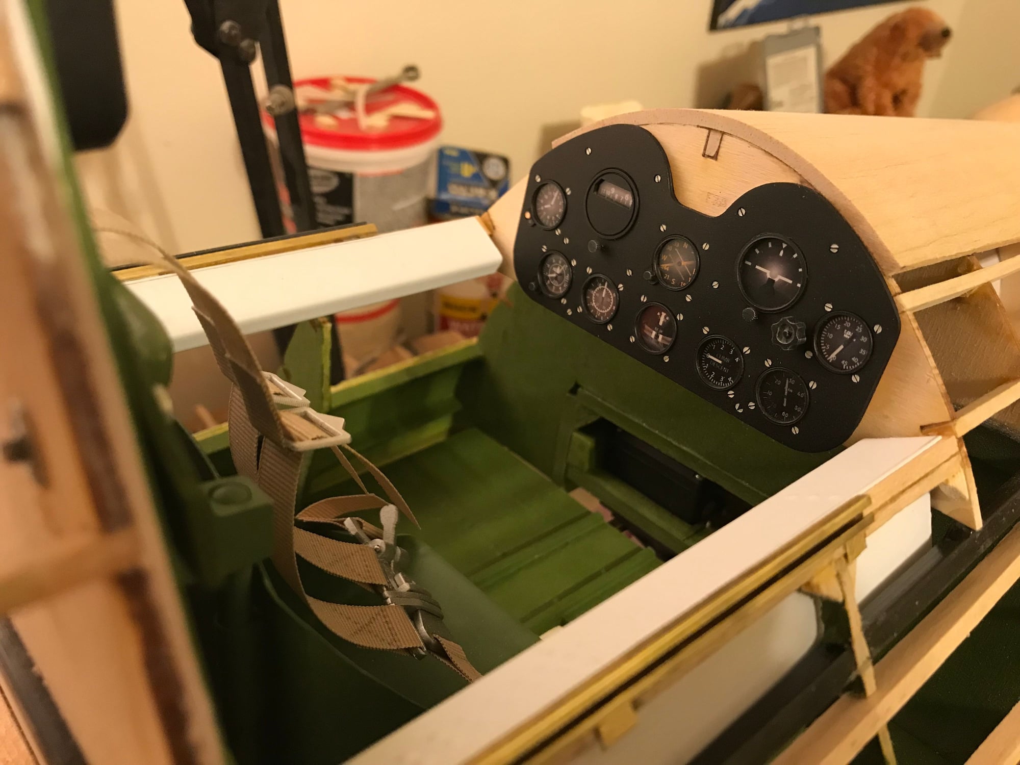
Working on front fuse/cockpit. Determined that canopy slide rails need to go in, before adding any more sheeting to the sides. And, to get side rail height correct, I need to fit the canopy. So, off to the front for a bit.
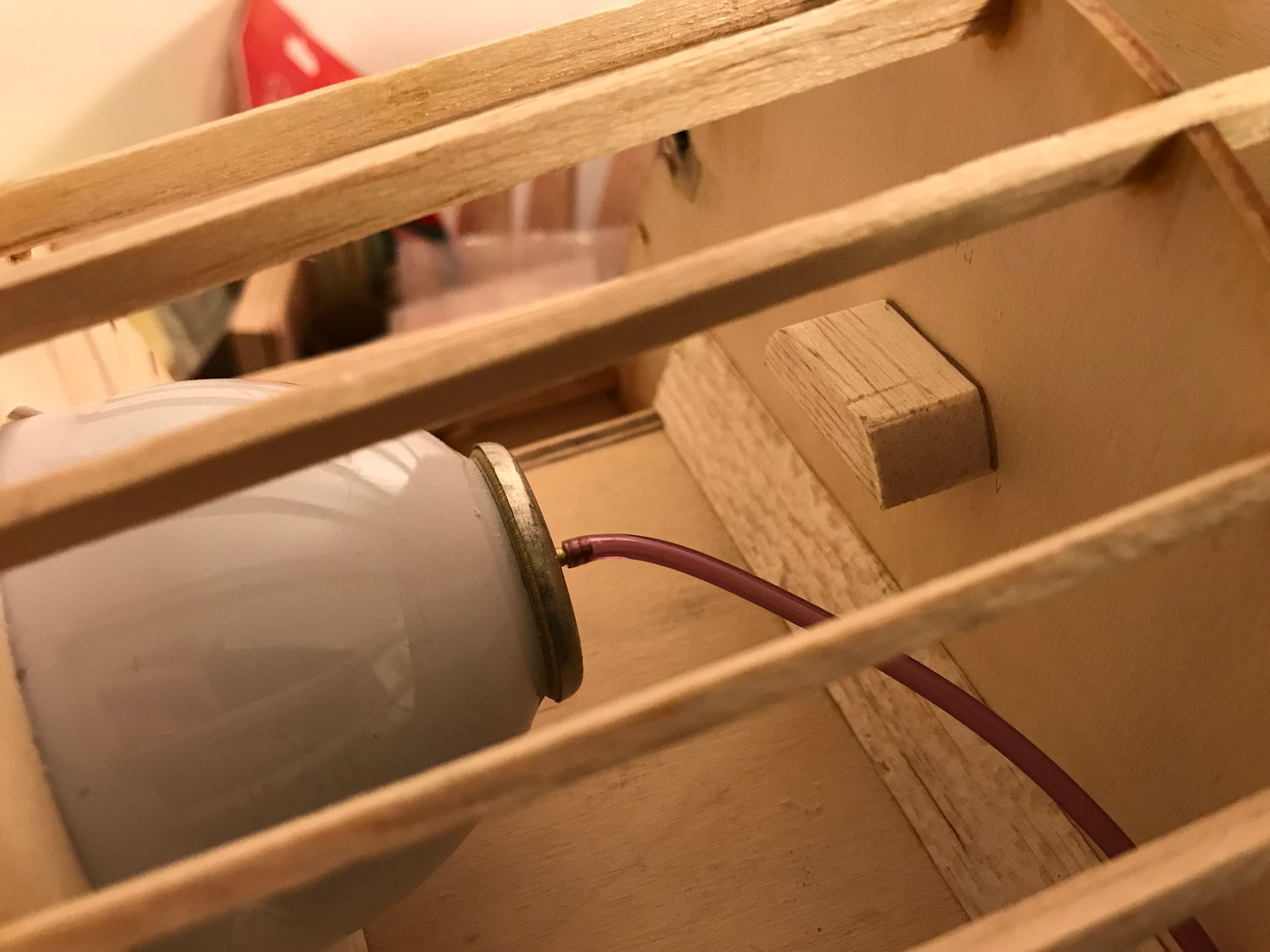
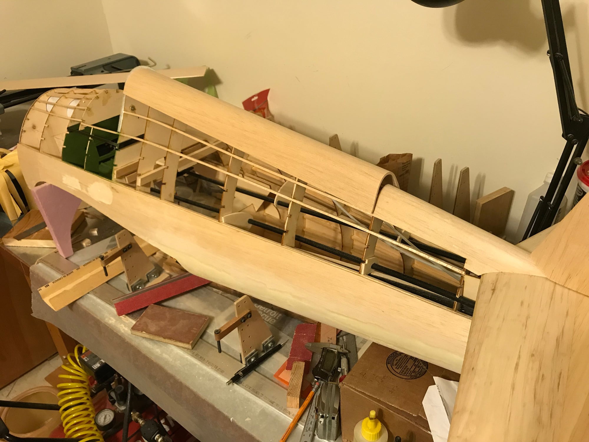
Installed stop to prevent air tank from being pushed back to far
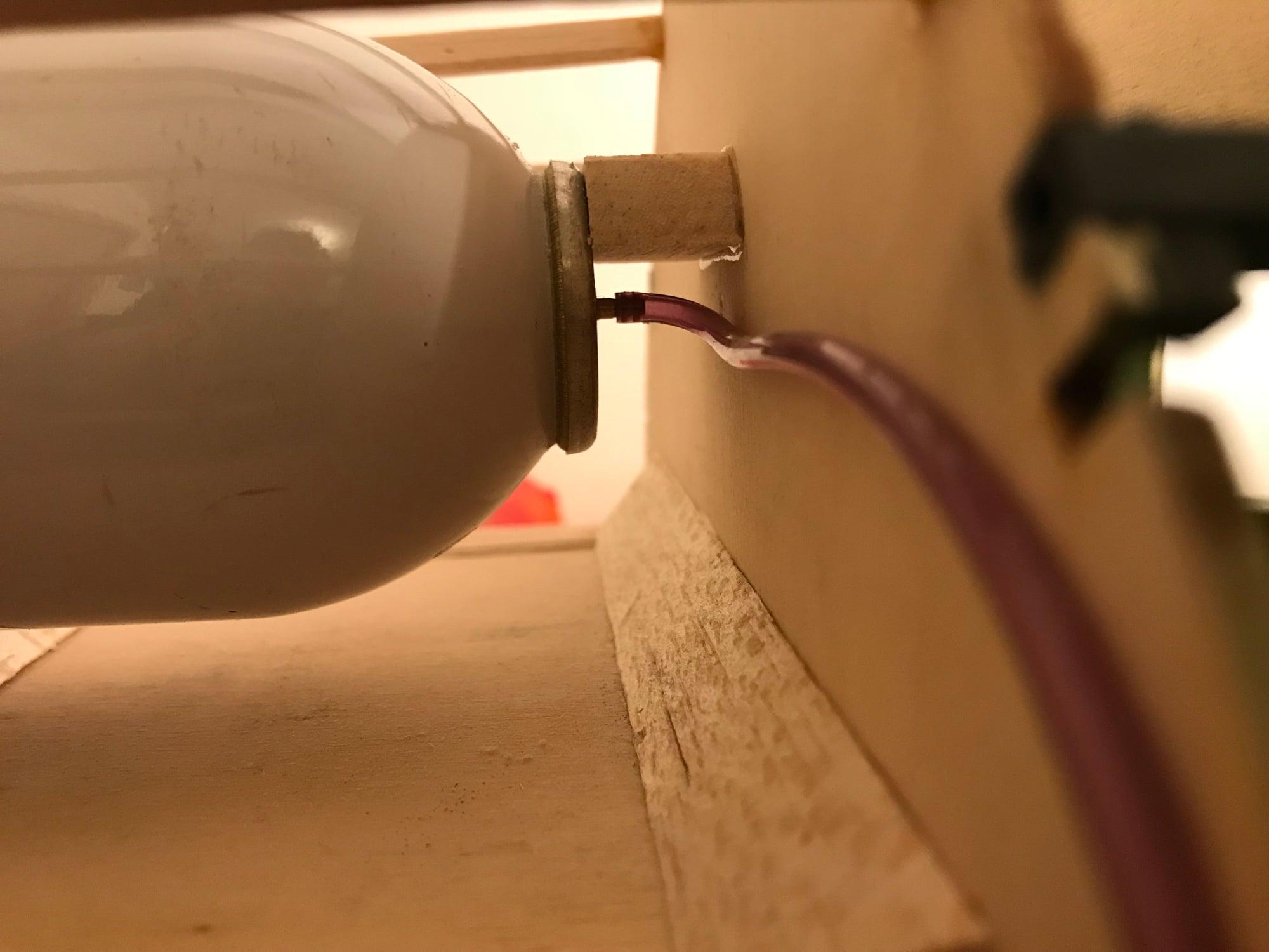
The stop works - no airline pinch!
Top deck strapped in while glue sets

Glue is set excess on either end sanded smooth
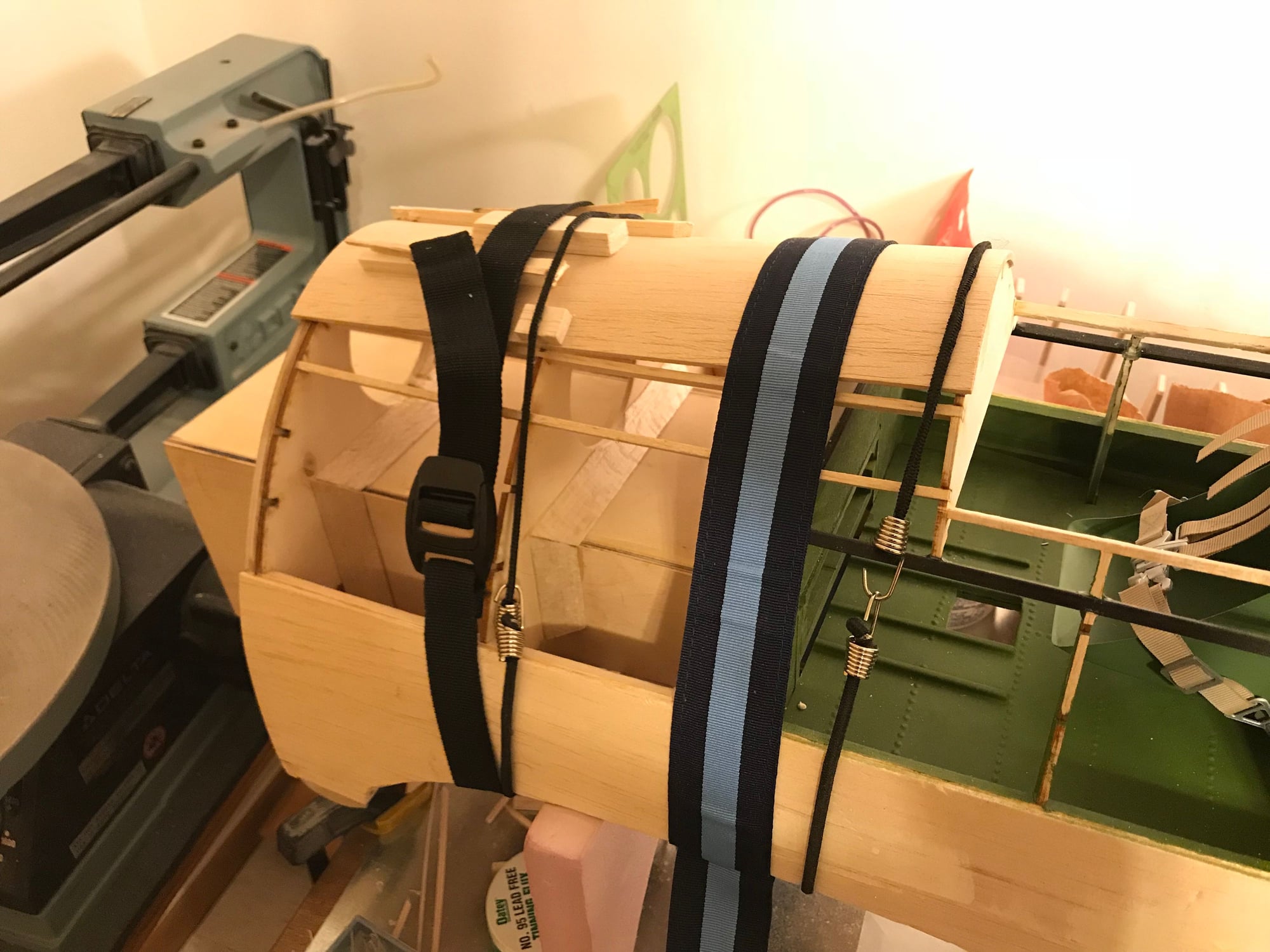
- First two pictures: Since I installed the air cylinder above the engine box, I added a stop to prevent the cylinder from being pushed to far back, potentially pinching the air line.
- Third picture: Top sheet installed. I used water/ammonia to curve the sheet, letting it try over night. Today, In glued it in place, using a variety of straps to hold it in place while the glue set
- Fourth picture: Glue set and ends sanded flush.
Installed stop to prevent air tank from being pushed back to far
The stop works - no airline pinch!
Top deck strapped in while glue sets
Glue is set excess on either end sanded smooth
04-10-2018, 06:36 PM
#198
Thread Starter
Canopy rails installed.
Pictures:

Fittings solderd in place, cut to length
Notches filed into stringers

Epoxied and clamped

Done!
Pictures:
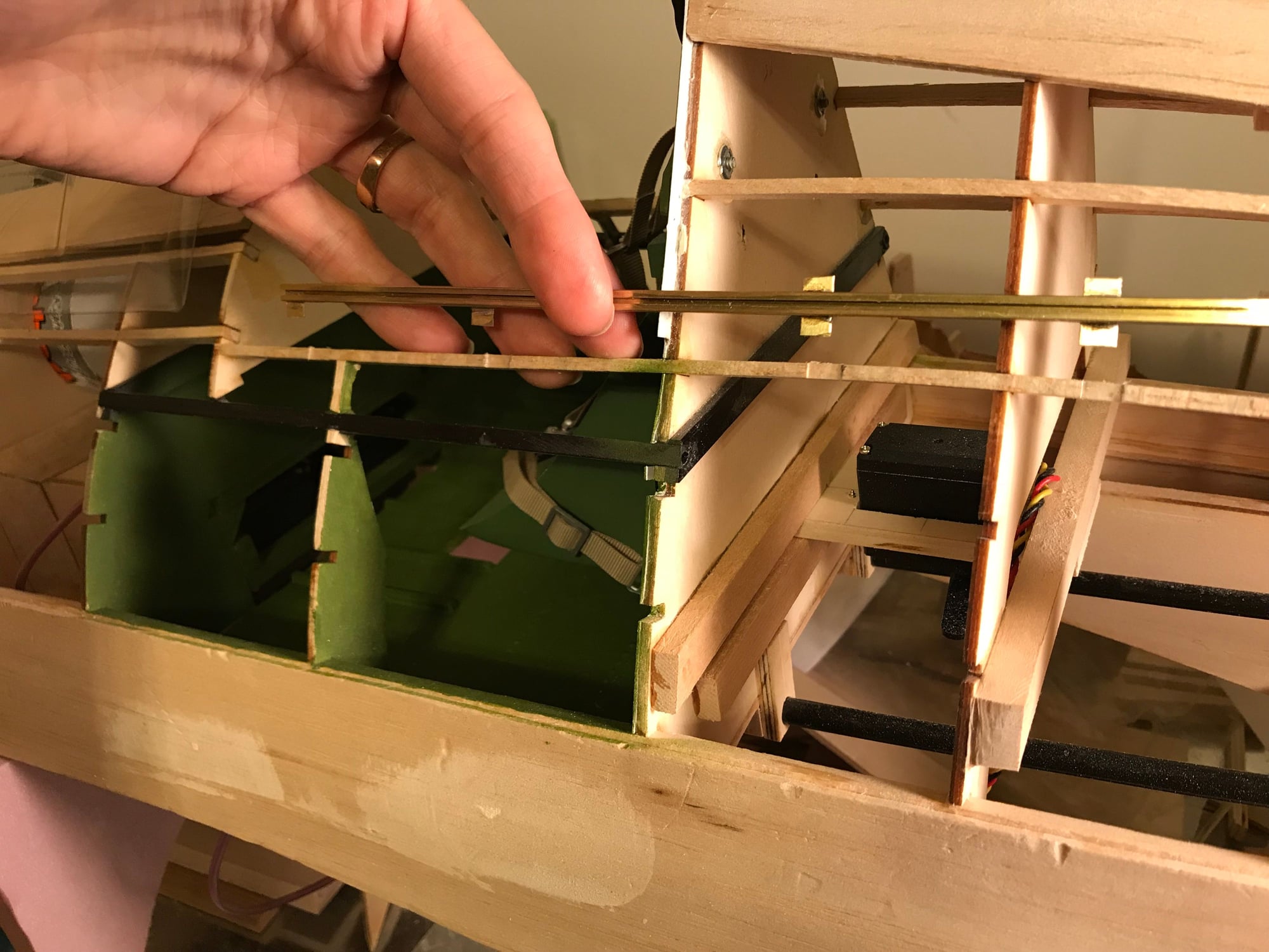
- Rails cut to length and fittings soldered in place. For the front, cockpit portion, there was much to attach the rail to, so I added a couple 'L' shaped bits. The rails shipped with flat strip brass, no angle strip. Also, my LHS didn't have any angle brass. As I wanted a sharp corner for this "L" bits, I ended up buying 3/32" square brass tube and cut the bits out using my Dremel with a cut-off wheel.
- Notched recesses filed into stringers to accept brass bits
- Rail epoxied and clamped
- Left rail done!
Fittings solderd in place, cut to length
Notches filed into stringers
Epoxied and clamped
Done!
04-14-2018, 07:16 PM
#199
Thread Starter
Finishing canopy rail installation:
Doubler stringer installed on left cockpit side
Chad's panel - encouragement to keep moving! Also, test fitting cockpit top-side pieces, and gussets added to stringer
- Added a doubler-stringer. Right side of the cockpit (picture left) shows the brass rail, its fittings, on top of the original stringer. Left cockpit side shows the doubler fitted and epoxied in place.
- There wasn't much surface area to glue the original stringer in place, so added several gussets. Then test fit the top-side canopy details and Chad's panel
Doubler stringer installed on left cockpit side
Chad's panel - encouragement to keep moving! Also, test fitting cockpit top-side pieces, and gussets added to stringer