


CARF SPITFIRE ASSEMBLY and SCALE DETAILING
 06-08-2016, 09:41 AM
#26
Member
Join Date: Feb 2004
Location: Este, ITALY
Posts: 84
Likes: 0
Received 0 Likes
on
0 Posts
Hi. I am going to buy a Carf spit too by the end of this year. I am searching for the right engine. I really love inline engine (4T) like Valach or Kolm but they are very expensive.. So i could choose the DA100i but searching on the web i have found an old engine revisited with GAS ignition: the MOKI G360. It's a 2 stroke inline engine that has about 7,7hp and is very light. Have you some drawing of the CARF cowl in order to check if the engine can fit inside ?I think it is a very small engine but i think it has the drive shaft a little bit short... here is a picture of the engine. Thanks. Nicola


 06-11-2016, 04:27 AM
#28
Member
Thread Starter
Join Date: Aug 2013
Posts: 36
Likes: 0
Received 0 Likes
on
0 Posts
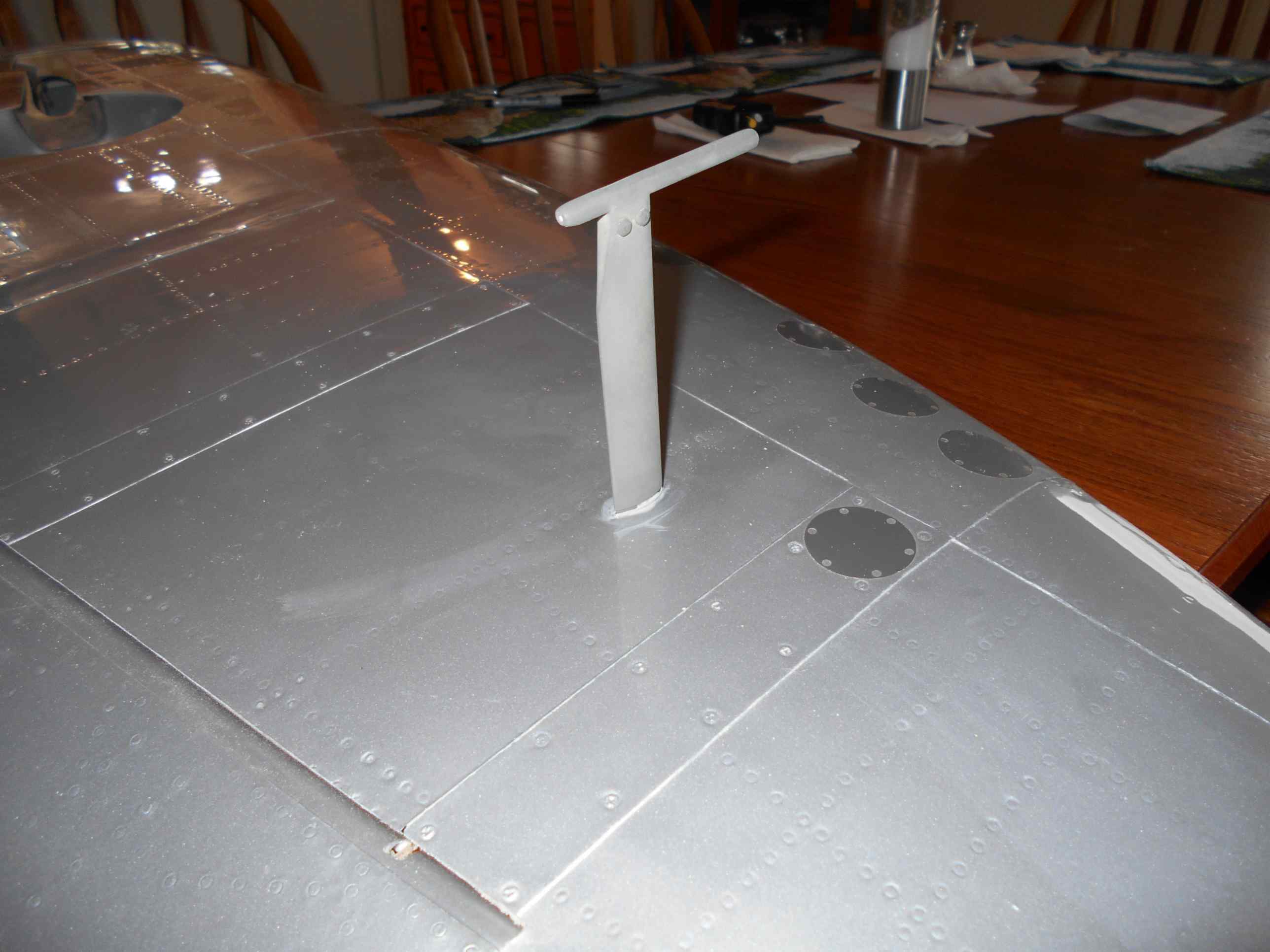
PITOT TUBE
As with the antennae, I wanted to make the Pitot removable from the wing to make it easier for storage.
The Pitot tube has 3 main sections, the female tube in the wing, the male attachment plug and the top part that is shaped like the Pitot tube on the real plane.
The dimensions of the Pitot tube and its location can be found in the Monforton book on page, 7.52.
Again I used Locktite Epoxy to hold the female tube to the inside of the wing.
06-11-2016, 08:01 AM
#29
Member
Thread Starter
Join Date: Aug 2013
Posts: 36
Likes: 0
Received 0 Likes
on
0 Posts
I tried the magnet idea with my big Harvard but wasn't happy with the lateral movement that I got. This way it is rigid in all directions and very easy to remove and put back on. But to each how they would solve a problem, there are many ways to reach the same goal.
06-11-2016, 08:07 AM
#30
Member
Thread Starter
Join Date: Aug 2013
Posts: 36
Likes: 0
Received 0 Likes
on
0 Posts
Hi. I am going to buy a Carf spit too by the end of this year. I am searching for the right engine. I really love inline engine (4T) like Valach or Kolm but they are very expensive.. So i could choose the DA100i but searching on the web i have found an old engine revisited with GAS ignition: the MOKI G360. It's a 2 stroke inline engine that has about 7,7hp and is very light. Have you some drawing of the CARF cowl in order to check if the engine can fit inside ?I think it is a very small engine but i think it has the drive shaft a little bit short... here is a picture of the engine. Thanks. Nicola
But why not buy a scale plastic model of this airplane and then measure the cowl, multiply it by the scale factor from the plastic model to the Carf kit (23%) and the4n you will see if you would be happy with the size of the hole in the bottom of the cowl.
06-15-2016, 03:29 AM
#31
Member
Thread Starter
Join Date: Aug 2013
Posts: 36
Likes: 0
Received 0 Likes
on
0 Posts
AERILON CONTROL INSTALLATION
Well I got through my first chemo and radiation treatment and I feel great. No sickness or tiredness yet.
I'm not a fan of two things that Carf wants you to do in mounting the aerilon servos.
First I do not like the Glass Fiber control horns. I had one break on my Carf 330SC when I accidentally hit the outside horn on my elevator. I replaced it with the Hanger 9 HAN 3615 Control horn and this system has worked great for me since. On my Krill after many flights I had the hole between the two fiber horns slightly elongate from the 4-40 bolt going through. This lead to some slop. So again I replaced it with a Hanger 9 Control Horn.
BUT I did follow exactly where Carf tells you to install the horns (1 inch in sideways and 1/2 inch down). There is a supporting block there that you drill through and it gives a lot of rigidity to the control horn assembly. I drilled the hole slightly undersize then tapped the wood for a 10-32 bolt. I used Locktite epoxy to hold it in place. The Philips flat head is countersunk and I will fill it in prior to painting and it will not bee seen.
I also was not a fan of the way the servo is buried deep into the top underside of the wing. This eliminates only 1/2 of the control linkage and does hide the control arm. But it puts it at a awkward angle for precise adjustment. On watching many videos of this plane flying, you can still see the control horns and part of the linkage, so I opted to not care that servo arm, the whole linkage and control horns would be seen.
I used the EXACT same servo hatches that came from my crashed Carf Extra 330sc. They still had the metal servo holders still attached.
I cut the servo hatch with my new HOT KNIFE. What a tool. as it does such an exacting job. I just lay a flexible ruler against the outside of the line and slowly cut away. Afterwards I followed Carf's advice and added the strengtheners between the upper and lower wing skins.
I'm using Savox 2270 Brushless servos for both aerilons.
06-16-2016, 04:24 AM
#34
Member
Thread Starter
Join Date: Aug 2013
Posts: 36
Likes: 0
Received 0 Likes
on
0 Posts
Last night after my second radiation treatment, I came home from a 2 hour drive to a burning pain in my chest and very very tired. I could not work on the plane.
But this morning, the pain is gone, so I did a bit more work on the cockpit that I will post soon. Unfortunately it's another 2 hour drive back up to the cancer clinic so it certainly eats into by building time. BUT I do get a lot of time to think and ponder how to resolve the next building phase for the plane. Weekends I don't get any treatment so hopefully I can post more then.
But this morning, the pain is gone, so I did a bit more work on the cockpit that I will post soon. Unfortunately it's another 2 hour drive back up to the cancer clinic so it certainly eats into by building time. BUT I do get a lot of time to think and ponder how to resolve the next building phase for the plane. Weekends I don't get any treatment so hopefully I can post more then.
06-17-2016, 02:04 PM
#35
Member
Thread Starter
Join Date: Aug 2013
Posts: 36
Likes: 0
Received 0 Likes
on
0 Posts
FLAP INSTALLATION
Similar to the aerilons, I went my own way. Reading several other builds on this Carf plane, it is apparent that it's very hard to get a total of 85 degrees deflection using the Carf method of completely hiding the control arm inside the wing.
I put the Flap control arm and the holding plate for the servo underneath the Oil Cooler and on the other wing under the Radiator. In this way very little is exposed of the control mechanism for the movement of the flap.
But since there is a lot of load against the flap when it is fully deployed, I added some extra support on the inside. All of this is held together with Locktite Epoxy glue. I purchased some control horns from SDS Hobbies and these were the parts that came with it. I drilled out the black nylon base to accept my own Hanger 9 10-32 bolt and clevis. The SDS bolt was only 3mm that I did not think was strong enough.
The weight for the parts for the flap system was 108 grams.
06-21-2016, 05:18 PM
#36
Member
Thread Starter
Join Date: Aug 2013
Posts: 36
Likes: 0
Received 0 Likes
on
0 Posts
REAR CANOPY
Well I have now into my second week of Chemo and Radiation and I have been fortunate in that I have had no nausea from the chemo. The radiation does tire me out a bit, but I do find enough energy to do about 2 hours of work a day on the Spitfire.
For the canopy formers I used a piece of 1/4 birch ply and shaped them to the required arc for the back support. I then used a piece of .025" styrene to cover the plywood, so it would not show any grain and look like painted steel.
There are many different pictures out there showing a variety of items used back there, but I chose the ones that came with my cockpit kit. To imitate the green zinc chromate green, I used Rustoleum's flat camouflage green paint.
For more pictures of the rear canopy visit this site for some inspiration. But remember, I am only trying to "Simulate" to interior, and am not trying to make a exact duplicate. This plane is to be used for Stand Off Scale and to have fun with, not a museum piece of work.
http://spitfiresite.com/2010/07/anat...html/07628_007
06-22-2016, 09:15 AM
#37
Member
Thread Starter
Join Date: Aug 2013
Posts: 36
Likes: 0
Received 0 Likes
on
0 Posts
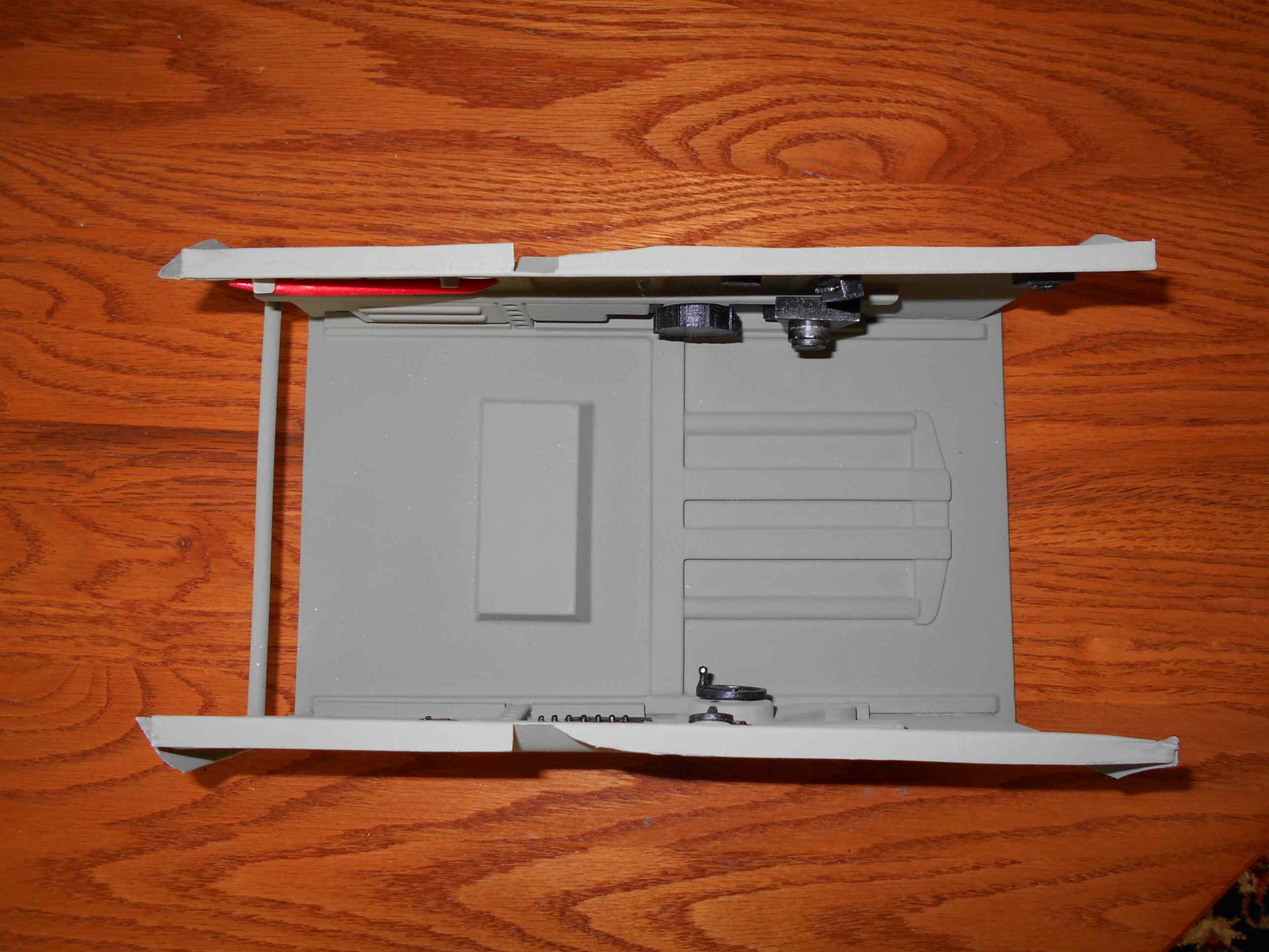
INTERIOR COCKPIT
When I was down at Joe Nall this year I got to see this very Spitfire with a multitude of engines in it. All had detailed cockpits, but for the most, Unless the Pilot was removed 90% of the details were obscured.
I therefore opted to spend just a modest amount of the money on the interior detail parts and spend MORE money on the Pilot which is clearly visible to all.
I got my Interior Cockpit parts form Tyspplanes.com. He shipped very quickly and the parts all arrived in a timely manner. He even threw in some extra parts.
You can watch two U-Tube videos on how to assemble the kit.
https://www.youtube.com/watch?v=o89f-0uqdwk
https://www.youtube.com/watch?v=no3iuOCZZ8U
The kit divides into four main subsection, The Rear Headrest Bullet proof section. The Floor and Side Walls, The Chair and finally the Instrument Panel.
I will discuss the Rear Headrest and the Floor and Head Walls in this section.
The Rear Headrest is a simple triangular shaped styrene part that you add a small piece of balsa to give it strength. I painted the Headrest first with matt black before proceeding to give the rest of the part the green cameo paint. I forgot to weight it but the weight is very small.
When I joined the two side walls to the floor, I just was not sure that the joints would be strong enough to take any long term flexing without cracking.
I added some 1/4" by 1/4' styrene square tubing to the bottom inside of the frame and it DRAMACTICALLY improved the rigidity. I also added a small styrene horizontal dowel to again reduce the movement.
Adding the "interior Components" is a bit of a hit and miss operation, the videos (2) give a few hints and on the various books out there they do show many more controls. But again I did not go overboard as once the pilot is in you can't see many of them. But the Red Crowbar is a "MUST".
Adding the cockpit interior cannot be left too late to do or it will become very difficult later on. I can now slide mine up right, thru the bottom front of the plane , turn it and it lays right in place. Once the top is glued in, I will then support the underside with some balsa triangular stock for even more rigidity.
The weight of this subsection is 191 grams.
This interior canopy DOES NOT lend itself to having an OPEN cockpit door for the Pilot to get in. I plan to "Simulate a Cockpit door with a hinge and a more defined space between the door and fuselage but mine will not actually open. This is something to ponder if you want a real door opening and you might have to look at an alternate interior kit.
Last edited by krazy kanuk; 06-22-2016 at 09:18 AM.
06-24-2016, 03:40 AM
#38

Join Date: Nov 2012
Location: , NY
Posts: 16
Likes: 0
Received 0 Likes
on
0 Posts
excellent job sir! I am truly impressed by the antenna and your vacuum forming skills. Great job. I am building a CARF Spit right now also....just installed the engine--a major job (major FW rework)...but it came out perfectly.
06-24-2016, 03:46 AM
#39
Member
Join Date: Feb 2004
Location: Este, ITALY
Posts: 84
Likes: 0
Received 0 Likes
on
0 Posts
06-24-2016, 07:52 PM
#44
Member
Join Date: Feb 2004
Location: Este, ITALY
Posts: 84
Likes: 0
Received 0 Likes
on
0 Posts
06-25-2016, 05:33 AM
#45
Member
Thread Starter
Join Date: Aug 2013
Posts: 36
Likes: 0
Received 0 Likes
on
0 Posts
INSTRUMENT PANEL
Well I am now thru my second week of chemo and radiation. It was not as easy as the first week so I have slowed down the amount of building that I am doing on the Spitfire.
The gauges that come with the semi scale from Tyspplanes.com. did not look that realistic to me so I ordered some 1/4 scale gauges made to WW2 British style.
I got them from HOBBY EXPRESS and they are made by www.aerocockpit.com. The look very realistic but they don't have a compass or the gun sight for the instrument panel.
I ordered both the compass and gun sight from Mic Reeves, but I had to do a fair amount of modifications to make them fit onto this panel.
I found a tiny true Hunter's compass at CTC that was just the exact size to fit into the Mic Reeves frame. I had to shorten Mic's gun sight so that it would fit onto the top of the panel.
All I need to do now is glue the panel in place and the cockpit interior details are done.
The size of the panel is about 6" by 6" and it weighs 62 grams.
06-26-2016, 03:47 AM
#47
Member
Thread Starter
Join Date: Aug 2013
Posts: 36
Likes: 0
Received 0 Likes
on
0 Posts
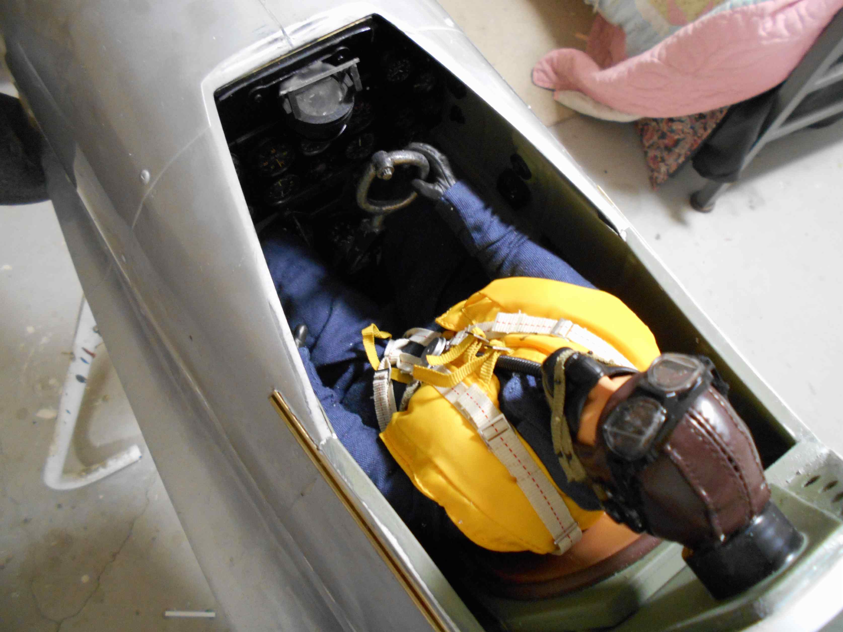
PILOT
I bought my pilot from Nick Ziroli https://ziroligiantscaleplans.com/sc...ot-figure.html
When at Joe Nall, I noticed in the four Carf Spitfires that most of the scale interior was hidden by the pilot. So I opted to spend my Cockpit money on what I thought most people would actually notice when they looked into the cockpit. Cost was about $98.
The pilot is 15 inches tall and weighs 202 grams.
I originally purchased a Hanger 9 1/4 scale pilot for $18. but I was very disappointed in it appearance. It just looked to much like a doll!
http://www.horizonhobby.com/product/...ot--25-han4566
06-27-2016, 01:56 AM
#48
Member
Thread Starter
Join Date: Aug 2013
Posts: 36
Likes: 0
Received 0 Likes
on
0 Posts
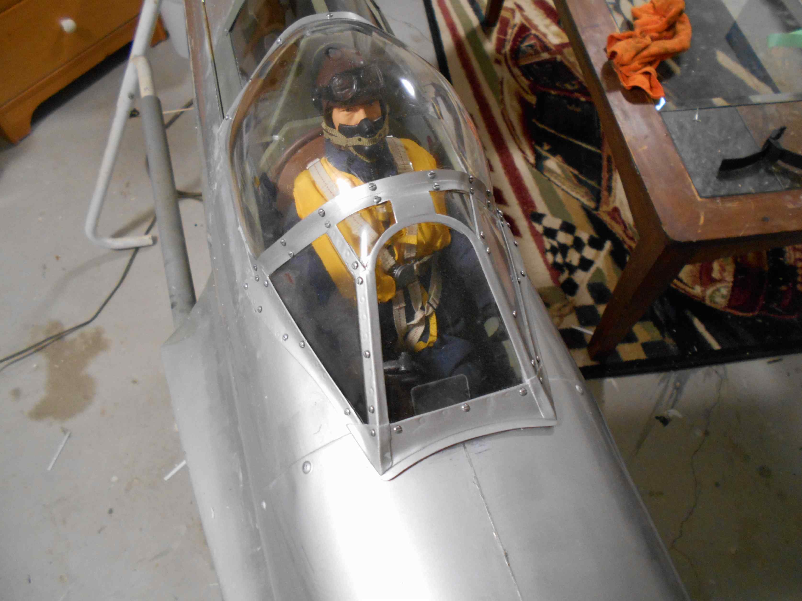
PILOT INSTALLATION
It's now two months into this build.
I got the pilot into the cockpit last night.
As I mentioned before he takes over the total interior and all of the subtle finishing touches down to the cockpit get buried out of sight.
I have now started work on the sliding canopy and that's my focus for the following week.
The next two days are very long ones up at the Sudbury Cancer Clinic so I'll not be posting much till the end of the week.
06-28-2016, 03:31 AM
#50
Member
Thread Starter
Join Date: Aug 2013
Posts: 36
Likes: 0
Received 0 Likes
on
0 Posts
Since the Pilot is 25% and the plane is 23 % when I lift the pilot's head it hits to top of the canopy and I cant get the canopy sliding motion to work. So it's a compromise!