


My Ziroli Hellcat build
 08-27-2016, 12:08 PM
#1

Thread Starter
Join Date: Nov 2014
Posts: 46
Likes: 0
Received 0 Likes
on
0 Posts
This will be my fourth plane from a kit that I will be building, and my first jump into giant scale. I am finishing up a TF .60 mustang with the B conversion kit. I have just started my build on this hellcat and I thought I would post this as insight to others and also so I can get advice along the way since this will be my first build without detailed instructions. I picked this kit up from National balsa this year at warbirds over delaware and my hope is to have it done for this coming Joe Nall event. So in that respect I don't plan to go crazy on the detail but enough to make it look nice. For the engine it looks like Saito will be releasing a FG-90R3 this October which will turn up to a 25x10. I am thinking this will be plenty for scale flight, I don't need a rocket. As for landing gear I'm thinking I'm going to go with robart electrics. So here we go...

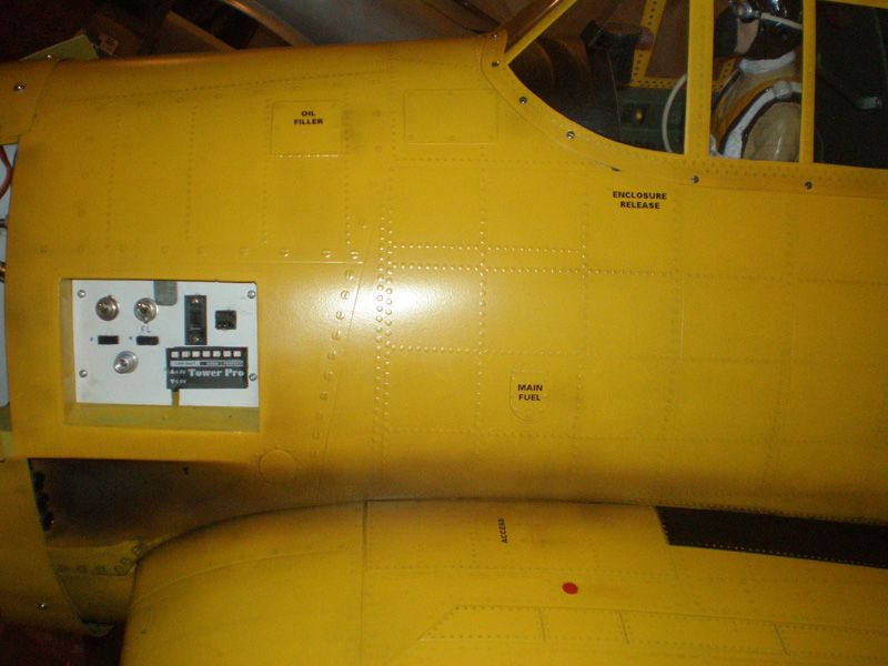
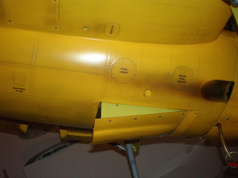
The scheme on the top is the one I plan to go with at least at this time

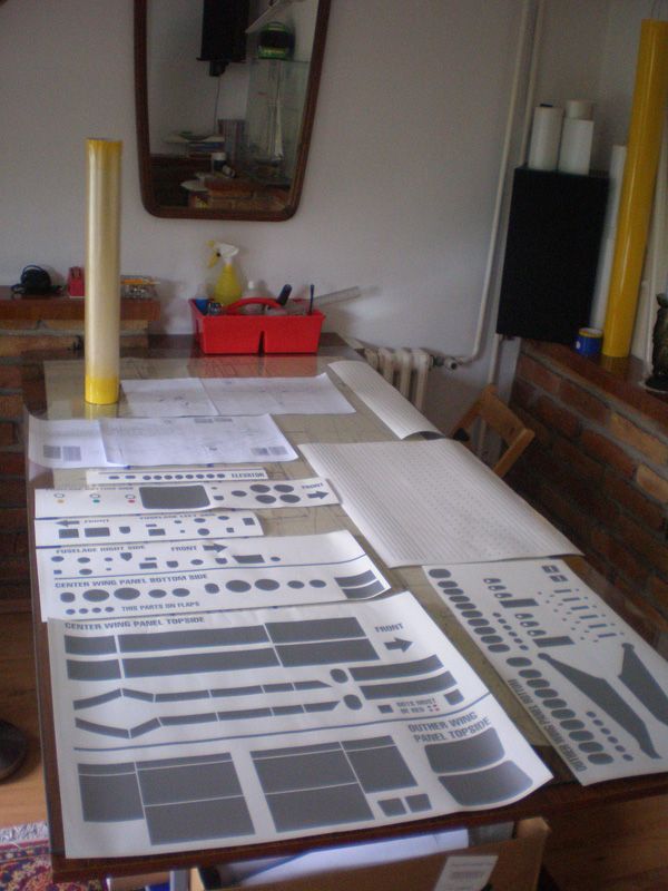
Starting off with a clean slate, it won't stay that way long. I found this awesome table on craigslist, the entire table is metal including the top surface. It is a pain to move but it works perfectly for building with magnets!


This is the method that I found works for me. I use titebond 2 on the top sheeting with magazines to keep equal pressure and keep all of the ribs flat on the table. Since there is no way to support it when doing the other side the sheeting will be attached with CA while holding it vertically.

First sheeting on with the grain going horizontal, the front portion goes on with the direction of the angle of the front of the stab.
The scheme on the top is the one I plan to go with at least at this time
Starting off with a clean slate, it won't stay that way long. I found this awesome table on craigslist, the entire table is metal including the top surface. It is a pain to move but it works perfectly for building with magnets!
This is the method that I found works for me. I use titebond 2 on the top sheeting with magazines to keep equal pressure and keep all of the ribs flat on the table. Since there is no way to support it when doing the other side the sheeting will be attached with CA while holding it vertically.
First sheeting on with the grain going horizontal, the front portion goes on with the direction of the angle of the front of the stab.
 08-29-2016, 05:02 PM
#2
Thread Starter
Join Date: Nov 2014
Posts: 46
Likes: 0
Received 0 Likes
on
0 Posts
One side sheeted. When doing this I found it was easier getting each piece situated where you want and good for making sure you have a good bond to the ribs. But it was more difficult getting a good bond between the leading and trailing sheets. I ended up with the leading sheet raised slightly from the tiniest bit if glue from when the trailing was glued on. Oh well sanding and light weight filler will hide any imperfections.
This time around I got the leading and trailing sheets glued together. This made for a much better seam, but also harder to make sure it was attached to all of the ribs with it being such a large surface and that all of tabs are gone so now you can't set it on the table with weight. All in all both ways worked, I think I'm leaning towards the second way better.
09-13-2016, 05:51 PM
#3
Thread Starter
Join Date: Nov 2014
Posts: 46
Likes: 0
Received 0 Likes
on
0 Posts
Horizontal stab pretty much complete besides some final sanding and a cote of hobbylite balsa filler. I used lightweight spackle on my last build and it never seemed to harden as much as hobbylite did so I'll spend a little more for it to be a stronger filler and easier to sand.
left elevator going together, it's not quite as easy as a top flite kit having to cut each individual piece except for what will go on the curved end. I plan to use a single joiner wire for hidden linkage and not having to worry about one servo failing on the two servo set up. any advise on that would be appreciated or where I might be able to purchase a good hardware kit for that.
10-04-2016, 11:52 AM
#5
Thread Starter
Join Date: Nov 2014
Posts: 46
Likes: 0
Received 0 Likes
on
0 Posts
second elevator is done
Now I have ran into a snag when building the crutch. I have it built perfectly over the plans but this inner wing saddle is supposed to be built into the inside of the crutch while on the building board. My problem is none of the cut outs line up with the ribs on the crutch. If I line the front up then the trailing edge is 1/4 of an inch to long and vice versa according to the plans. You can see that WS-1 the inner wing saddle matches up perfectly to the plan, I was thinking maybe my issue was that is was cut wrong. Everything on my plans matches exactly but won't fit together, I know I've got to be missing something. Any help here is appreciated. I have left a message with Ziroli as well and I am hoping to hear back soon on what to do.
10-04-2016, 04:22 PM
#6
Thread Starter
Join Date: Nov 2014
Posts: 46
Likes: 0
Received 0 Likes
on
0 Posts
Here are a few more pictures of what is going on. In the first picture it is lined up with where it should end at the rear and there is a lot of overhang and no alignment of the slots, and the second picture shows if I line it up on the front how far past it goes on the rear of the shaded section. My brain is fried at this point.
10-04-2016, 06:59 PM
#7


Join Date: Mar 2007
Location: Bountiful, UT
Posts: 112
Likes: 0
Received 0 Likes
on
0 Posts
That looks to me like the plans were printed scaled slightly wrong. Where did you get the plans? Is there a reference dimension anywhere that you can measure? Hopefully Ziroli will respond to your inquiry. I'm planning to build this one soon-ish, so I'd like to see this resolved for you. Good luck!
10-04-2016, 08:45 PM
#8
Thread Starter
Join Date: Nov 2014
Posts: 46
Likes: 0
Received 0 Likes
on
0 Posts
The kit was purchased from national balsa, the plans I bought directly from ziroli. I had figured something along the same lines that you suggest, what doesn't make sense is that the part matches the part outline perfectly in the plans. Maybe someone can give me their measurements between the braces on the crutch on their plans. Thanks for the insight.
Last edited by DanIsGo; 10-04-2016 at 08:47 PM.
10-04-2016, 10:46 PM
#9
Join Date: Mar 2007
Location: Bountiful, UT
Posts: 112
Likes: 0
Received 0 Likes
on
0 Posts
Strange indeed. Have you been over to rcscalebuilder.com? There are many excellent scale builders on there that could probably help. Many of the actual kit designers are on there also.
Last edited by hessian123; 10-05-2016 at 06:24 AM. Reason: Fixed typo
10-05-2016, 10:43 AM
#10
Thread Starter
Join Date: Nov 2014
Posts: 46
Likes: 0
Received 0 Likes
on
0 Posts
I have been on there but I haven't asked any questions in hopes that I don't have to follow more than one thread. I got a call from Ziroli today that their tech guy will be in tomorrow, so fingers crossed I can get this all figured out then. I can't wait to get this part of the build going, this wait is killing me.
10-05-2016, 08:35 PM
#11
Thread Starter
Join Date: Nov 2014
Posts: 46
Likes: 0
Received 0 Likes
on
0 Posts
After staring at this for hours I think you are right as far as the plane being printed off scale. I will know for sure tomorrow after talking to ziroli tomorrow. If that is the case it looks to be only the fuselage print because with the horizontal stab everything came out in perfect alignment. If this is the case it will hold my build up at least another week, unless I just decide to work on the wing instead. Hopefully that was printed correctly.
10-06-2016, 06:53 PM
#12
Thread Starter
Join Date: Nov 2014
Posts: 46
Likes: 0
Received 0 Likes
on
0 Posts
Okay well I got a hold of the tech guy at ziroli and he told me not to worry about wher the braces are outlined in the plans. He said to install the inner wing saddles and use that to determine where to put the braces. He said because of the curvature of the fuse that apparently the braces show up a little off. I am still a little worried to be honest because those braces determine the placement of all of the fuse section parts. So I guess we will see how everything lines up before gluing it all together. Tomorrow should make for decent progress.
10-08-2016, 01:35 PM
#14
Thread Starter
Join Date: Nov 2014
Posts: 46
Likes: 0
Received 0 Likes
on
0 Posts
okay so all of the circled areas where it meets the crutch there are large gaps on both sides about 1/8 of an inch maybe more in some spots. on the very first former where it is circles is where the outer wing saddle is supposed to attach it sits about 1/8 of and inch behind it and it is supposed to attach to the side of it. Also the line I drew at the cockpit is to show where I had a gap when installing the cockpit floor.
on this you can see the poor alignment of the spacing after I moved the outside of the crutch to the proper width that you can see I have marked in the next picture. I found this width by measuring the width on the formers so that they would now be fully seated against the side of the crutch
This is a picture of the motor box and how it is aligned poorly.
my frustrations got to me and i started tearing everything apart before I was able to get good pictures.
10-08-2016, 07:36 PM
#15
Thread Starter
Join Date: Nov 2014
Posts: 46
Likes: 0
Received 0 Likes
on
0 Posts
After scrutinizing other builds maybe I'm just too worried about perfect fitment everywhere. I will take another attempt at building the crutch to my standards and see how it goes this time seeing as I have already learned what not to do haha.
10-08-2016, 08:28 PM
#16
Join Date: Mar 2007
Location: Bountiful, UT
Posts: 112
Likes: 0
Received 0 Likes
on
0 Posts
Sounds like a good plan. I haven't laid eyes on the plans or build instructions (are there instructions?), but maybe changing the order of how it's built would help. Maybe set the formers up over the plans on crutch/stands, then add the stick parts? Best of luck!
10-08-2016, 08:44 PM
#17
Join Date: Mar 2007
Location: Bountiful, UT
Posts: 112
Likes: 0
Received 0 Likes
on
0 Posts
I'm not sure what it means, but there's some pretty good photos of the framed up fuse in this other thread, and I don't even see that inner saddle piece installed.
http://www.rcgroups.com/forums/showp...2&postcount=37
Another good thread with maybe even better photos:
http://www.rcuniverse.com/forum/rc-w...l#post10305836
http://www.rcgroups.com/forums/showp...2&postcount=37
Another good thread with maybe even better photos:
http://www.rcuniverse.com/forum/rc-w...l#post10305836
Last edited by hessian123; 10-08-2016 at 09:09 PM. Reason: Added second link.
10-09-2016, 04:28 AM
#18
Thread Starter
Join Date: Nov 2014
Posts: 46
Likes: 0
Received 0 Likes
on
0 Posts
Hey thanks for those! Somehow I missed those ones. In the second link you showed me it looks like that guy ran into the same problem as me as far as the outer wing saddle not reaching the first former looking at post 19. Maybe I didn't need to tear it all apart, but I am used to kits falling together a little better than this and now I can adjust for what I saw that wasn't satisfactory.
10-16-2016, 11:08 PM
#19
Here you can find good building topic of Ziroli F6F:
http://www.nsmodelers.rs/warbirds/he...septembar-2010

Text is on Serbian language, but you can see more that 1000 pictures of all building stages. Later you can see video form airfield...
Don't forget, on same web site you can order many sets for scale Hellcat finish...
http://www.nsmodelers.rs/home/detail-set-za-ziroli-f6f
Take care during building to put all parts as forward as possible. Hellcat is "short" in front and if you add parts in rear of the model will have problem with CG...
Best regards
Mirce
http://www.nsmodelers.rs/warbirds/he...septembar-2010


Text is on Serbian language, but you can see more that 1000 pictures of all building stages. Later you can see video form airfield...
Don't forget, on same web site you can order many sets for scale Hellcat finish...
http://www.nsmodelers.rs/home/detail-set-za-ziroli-f6f

Take care during building to put all parts as forward as possible. Hellcat is "short" in front and if you add parts in rear of the model will have problem with CG...
Best regards
Mirce
10-21-2016, 09:24 PM
#20
Thread Starter
Join Date: Nov 2014
Posts: 46
Likes: 0
Received 0 Likes
on
0 Posts
Thanks, I have actually been planning on getting that detail kit from you for sure! I have not planned on putting anything extra in the rear, just building per the plans. One thing I did was get the servo operated tail gear so that I can locate it the servo up front instead of having the valve/electric actuator in the rear. I have actually moved my build thread over to rc scale builder, so here is the link for anyone that was following. http://www.rcscalebuilder.com/forum/...802&PN=1&TPN=1 I have a few pictures to move over and a few more updates to post, I hope to have them up soon.
