


Jerry Bates P-51B Build "Hell Yes Let's Go!!!"
 10-13-2016, 08:09 PM
#26

Thread Starter
My Feedback: (13)

Join Date: Oct 2003
Location: C/S CO
Posts: 730
Likes: 0
Received 0 Likes
on
0 Posts
I'm sure your electric mustang is without a doubt faster than any gas competitor of equal size as is the reliable power and ease of daily flying. I've never really got into elec's on anything larger than 60+" 3d planes however I do see the advantages.
Regarding your ZDZ...You could actually increase the base gasket thickness by a few thous to slightly help reduce the compression ratio. I have done the exact opposite by decreasing the base gasket thickness to increase compression = slight hp gains. I've done this primarily due to the altitude we fly at in Colorado. +6,000 ft at the field = everything bad for rc planes. Thin air = less lift and less prop thrust performance. Low oxygen= less fuel for proper mixture making lower hp. I have a CNC cutter and have cut several thinner copper gaskets for different engines with fair results.
Regarding your ZDZ...You could actually increase the base gasket thickness by a few thous to slightly help reduce the compression ratio. I have done the exact opposite by decreasing the base gasket thickness to increase compression = slight hp gains. I've done this primarily due to the altitude we fly at in Colorado. +6,000 ft at the field = everything bad for rc planes. Thin air = less lift and less prop thrust performance. Low oxygen= less fuel for proper mixture making lower hp. I have a CNC cutter and have cut several thinner copper gaskets for different engines with fair results.
 10-14-2016, 05:05 AM
#27

Some time after I put the ZDZ aside to concentrate on getting more performance out of smaller engines by working on streamlining to reduce drag, I thought about a thicker base gasket. I also considered a smaller carb bore, then, when I measured the carb bore size for 3 different size engines, I found that they were all the same bore. I also considered putting a restrictor plate in the intake manifold. A machinist also suggested a flywheel as a means of smoothing out the power stroke, but an experience while riding in a friend's 56 chevy ( the flywheel exploded when he missed the shift to third gear), discouraged me from trying a flywheel solution. The idea of a flywheel detonating at high rpm and thowing shrapnel, possibly hurting anybody within range ended that idea.
I would like to use the ZDZ but the lack of a suitable cheap, throwaway airframe (the 3d plane I had used for testing the ZDZ was wrecked),(brain fart), has delayed further work in that area.
Getting into warbirds was the reason I started using lower displacement engines to get a smoother running airframe and engine package. My brothers anti-vibration work on his Quadra 52 (absolutely the most vibration I have seen in a model engine) was another look at reducing the shakes. I was told by several modelers that the 3W engines were smooth running but my observations of the (low) vibration levels that they thought were getting nixed that idea.
10-14-2016, 02:06 PM
#28
My Feedback: (37)
I know what you mean about gas engines and its vibration, vibration plays a big role in the life of your airplanes. I basically had to learn to build again when I went from large glow Moki engines to Sachs, Zenoah G62s and 3Ws. The heavier your model is the better, it can absorb some of the vibrations. These days if it is a round cowl I use a twin, my Seafury and LA-7 have GT80s and Bearcat has a modified DLE60 twin. The DLE55 is not so bad with vibration and for this P51B or a Hanger 9 P51 is a perfect motor. I will probably never use a DA-85 or DLE-85 an inline twin will be better option. The Old Crow above flew at the rockies just fine with a DLE55-RA and it is only 1lb heavier than the plastic covered Hanger 9 P51. If you want a smoother gas engines maybe it is back to OS engines?
Last edited by fw190; 10-14-2016 at 02:10 PM.
10-14-2016, 05:39 PM
#29
Thread Starter
My Feedback: (13)
Join Date: Oct 2003
Location: C/S CO
Posts: 730
Likes: 0
Received 0 Likes
on
0 Posts
Well the Fuse is here and it's a beaut! Vic's work and molds are just awesome!. His attention to detail on this was just perfect. Cannot find one single air bubble or pinhole. What really sets his Fuses apart from others is that he actually keeps the panel lines to scale as much as possible. he has the slightly raised areas indicated with a fingernail feel at best which is perfect! As well as the tiny gap and recess of the panel lines. This will allow for a very scale look considering full scale panel lines are nothing more than the sheeting butt joints. His reveals will give just the right look when properly weathered and painted. It will be very hard to see how much detail is actually in the naked fuse in the photos but I promise you it is just about perfect. One thing I really don't care for on many of the top name ARF kits is the over exaggerated panel line width's and depths as well as the monster size rivets and screws.


Malcom canopy glass Standard canopy glass
I think I'm gonna start off by trimming out the canopy framework while I'm waiting on the wood kit. This should help get my mind dialed into this build.
Malcom canopy glass Standard canopy glass
I think I'm gonna start off by trimming out the canopy framework while I'm waiting on the wood kit. This should help get my mind dialed into this build.
Last edited by propwashed; 10-14-2016 at 05:41 PM.
10-14-2016, 08:37 PM
#31
Thread Starter
My Feedback: (13)
Join Date: Oct 2003
Location: C/S CO
Posts: 730
Likes: 0
Received 0 Likes
on
0 Posts
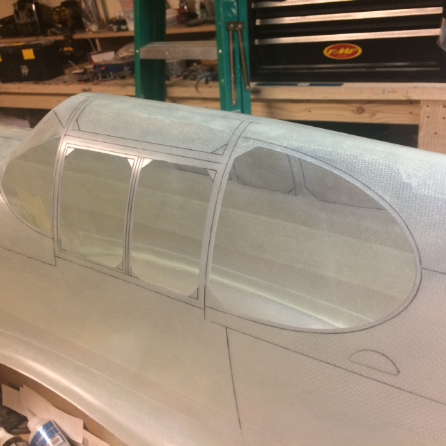
Getting started on the canopy cutouts:
Starting with a standard sharpie I traced all of the lines around the canopy to better see what all is going on here. Then lightly wipe of any extra marker with acetone to really define all the lines. There are plenty of panel, hinge, framework and cutout lines around the canopy. Very detailed


Once determined where all the glass will go I used a dremel with cutting disk to cut as close as possible to the inner lines. Leaving enough to sand with the drum bit and finally with a piece of 1/2" triangle stock with 120 grit stick on sandpaper wrapping all three sides. With all the joints filled with the black marker it allows you to fine sand right up to the inner line and once the line disappears, you are there.
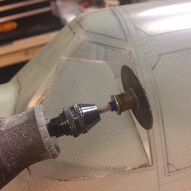


The standard fiber/resin dremel cutoff disks do not work as well as the higher dollar gold carbide disk for cutting. They burn more than cut through. I switched after the first cut out.
Obviously taking your time especially in the corners is critical because this will be the finished frame.
All of the correct framework lines are molded into the fuse. Even in between the glass panels. Very Nice!


On to the other side....
Starting with a standard sharpie I traced all of the lines around the canopy to better see what all is going on here. Then lightly wipe of any extra marker with acetone to really define all the lines. There are plenty of panel, hinge, framework and cutout lines around the canopy. Very detailed
Once determined where all the glass will go I used a dremel with cutting disk to cut as close as possible to the inner lines. Leaving enough to sand with the drum bit and finally with a piece of 1/2" triangle stock with 120 grit stick on sandpaper wrapping all three sides. With all the joints filled with the black marker it allows you to fine sand right up to the inner line and once the line disappears, you are there.
The standard fiber/resin dremel cutoff disks do not work as well as the higher dollar gold carbide disk for cutting. They burn more than cut through. I switched after the first cut out.
Obviously taking your time especially in the corners is critical because this will be the finished frame.
All of the correct framework lines are molded into the fuse. Even in between the glass panels. Very Nice!
On to the other side....
Last edited by propwashed; 10-15-2016 at 07:53 AM.
10-15-2016, 01:27 PM
#34
Thread Starter
My Feedback: (13)
Join Date: Oct 2003
Location: C/S CO
Posts: 730
Likes: 0
Received 0 Likes
on
0 Posts
I don't believe so. I believe the molded canopy will fit up through the bottom. It may be required for the side rear windows. And if I install the Malcom it would require some mods I'm sure. Still undecided on how I will have the canopy function. The standard has side access and the Malcom would slide back over the turtle deck. It will take some thought to get it all correct. Vic, chime in if you can.
Last edited by propwashed; 10-15-2016 at 01:30 PM.
10-16-2016, 12:09 AM
#37
My Feedback: (37)
The canopy gets glued from the inside. I use micro screws to put them, there are many ways. The Malcolm canopy sits above the frame. Primer and smooth out the inside of the fuselage to prevent scratching the canopy.


Notice the rear wing mount former, it is behind the step down surface for the belly scoop. You will need to notch the fuselage to fit the wing into the notch once you have the wing someone built. Smooth out


Notice the rear wing mount former, it is behind the step down surface for the belly scoop. You will need to notch the fuselage to fit the wing into the notch once you have the wing someone built. Smooth out
Last edited by fw190; 10-16-2016 at 12:14 AM.

 10-16-2016, 07:44 AM
#40
It looks very good, I have built several B models in the past and a very labor intensive part is masking the canopy for painting (I used liquid masking film). I think I will install the windows AFTER painting inside and out. I still haven't received the plans I ordered.
10-16-2016, 12:53 PM
#41
Thread Starter
My Feedback: (13)
Join Date: Oct 2003
Location: C/S CO
Posts: 730
Likes: 0
Received 0 Likes
on
0 Posts
Thanks Vic for the info on the canopy. The B is a bit of a challenge considering the standard canopy does not slide back or come off. Will make the cockpit a bit more difficult to build and detail. Vic did you make your malcom canopy removable?
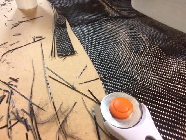
Made a little more progress today. A flying buddy let me borrow some carbon fiber cloth and some west systems. I was able to get going on the former reinforcement. Using Vic's method, pulling out some strands of cf wetting it and using it as a fillet in the joint. works well.


Thanks for coming over to help out last night Rob.
Made a little more progress today. A flying buddy let me borrow some carbon fiber cloth and some west systems. I was able to get going on the former reinforcement. Using Vic's method, pulling out some strands of cf wetting it and using it as a fillet in the joint. works well.
Thanks for coming over to help out last night Rob.
10-16-2016, 02:18 PM
#42
My Feedback: (37)
Tripp that is some nice clean gluing considering your pulling carbon from cloth instead of from a tow.
I have always used this method for a long time now, a fiberglass tow will work as well. Here is a place to get 50k strand carbon tow https://www.acpsales.com/OnlineStore.php?cat=4999
I have always used this method for a long time now, a fiberglass tow will work as well. Here is a place to get 50k strand carbon tow https://www.acpsales.com/OnlineStore.php?cat=4999
10-16-2016, 03:25 PM
#43
Thread Starter
My Feedback: (13)
Join Date: Oct 2003
Location: C/S CO
Posts: 730
Likes: 0
Received 0 Likes
on
0 Posts
Thanks Vic, I'm trying... The strands from the twill weave cf cloth has been pretty easy to work with once dampened as you mentioned to do with the tow. take 3-4 stands and they hold together pretty good
More former installation...Former F-8


Vic, quick question...Will the belly scoop on this build be permanently mounted to the wing after fitment or will it be mounted to the fuse allowing the wing to slip under?
More former installation...Former F-8
Vic, quick question...Will the belly scoop on this build be permanently mounted to the wing after fitment or will it be mounted to the fuse allowing the wing to slip under?
Last edited by propwashed; 10-16-2016 at 03:32 PM.
10-16-2016, 03:54 PM
#44
Thread Starter
My Feedback: (13)
Join Date: Oct 2003
Location: C/S CO
Posts: 730
Likes: 0
Received 0 Likes
on
0 Posts
Bob had my wood kit cut in a couple of days from when I placed the order. Delivered in about a week from ordering.
Vic was rocket fast on laying up the fuse and shipping it!
I'm hoping to be able to build a cockpit and insert in in from the bottom. Fortunately the radio and servo tray sit just behind and under were the cockpit will primarily be
This were I'm at for now until the resin sets up
Items I used for the former installation:
West Systems epoxy resin #105 and hardner #209 extra slow set (I would prefer/suggest the 206 or 205 hardener but hey this is what we had on hand)
3:1 ratio Epoxy to Hardener
A couple of old paint brushes one course one med (the longer the better)
Med CA and accelerator. to tac-glue formers in place
Small 1oz mixing cups. make small quantities it goes a long way
Some CF cloth
80 grit sandpaper
Acetone for surface prep and cleanup
Last edited by propwashed; 10-16-2016 at 08:10 PM.
10-16-2016, 08:06 PM
#46
Thread Starter
My Feedback: (13)
Join Date: Oct 2003
Location: C/S CO
Posts: 730
Likes: 0
Received 0 Likes
on
0 Posts
Couldn't leave it alone. Began installing the rear cockpit formers and radio tray. This takes a bit of time to get lined up properly. You definitely need to mock this area up and really check your reveals and depth from the rear windows to the radio tray and make sure its sitting square and level across the fuse
.


.
10-17-2016, 05:27 AM
#48
Thread Starter
My Feedback: (13)
Join Date: Oct 2003
Location: C/S CO
Posts: 730
Likes: 0
Received 0 Likes
on
0 Posts
Yes, that's the plan now. There seems to be plenty of room for a cockpit to be inserted from the bottom. The radio tray area behind the pilot seat should be painted and detailed prior to closing it up. I'll be painting and constructing the radio equipment prior to installing the rear windows. The rear windows will need to be cut from clear plastic and glued in.
More former installation:


the servo tray will be installed under the radio tray. that will be next.
More former installation:
the servo tray will be installed under the radio tray. that will be next.
10-17-2016, 09:59 AM
#49
Thread Starter
My Feedback: (13)
Join Date: Oct 2003
Location: C/S CO
Posts: 730
Likes: 0
Received 0 Likes
on
0 Posts
I also went ahead and cut out the radiator rear exit scoop. .
I used a razor blade to cut this out so I can re use the bottom and minimize the gap.This requires some patience and care.
I will be making the rear scoop functional.


I used a razor blade to cut this out so I can re use the bottom and minimize the gap.This requires some patience and care.
I will be making the rear scoop functional.
Last edited by propwashed; 10-17-2016 at 10:12 AM.
10-17-2016, 11:01 AM
#50
The post office says my plans are at the local PO. It was raining Sat., so she didn't leave them at the gate. My close inspection of my TF GS P-51B revealed some structural cracks that will need stripping the film off and rebuilding the fuse. The only other option is a new fuse but Tower has raised the price to $229 so I will retire it and hang it from the ceiling. It has a lot of flights, a crash, 3 wings, 3 power plants and several hard landing repairs. I will proceed on to build the Jerry Bates design with the glass fuselage and some day get around to repairing the TF B model, which is my pit crewman's favorite plane. I will have to use the same squadron markings on the new B model to keep him happy.