


Jerry Bates P-51B Build "Hell Yes Let's Go!!!"
 10-20-2016, 02:15 AM
#76

While studying the wing design I see that the flap hinging is in the center of the chord. This produces a nice tight hinge line but is not full scale and does not offer any lift advantages when the flaps are lowered. I have been modifying the flap hinging on my TF wings to bottom hinging and incorporating a venturi slot for additional low speed lift. This is easy to do and in the case of of the TF model, gives the plane better low speed handling and a more stable stall characteristic. My 29 lb TF B model does not drop a wing when it stalls, it just lowers its nose and continues down at a steeper, slower glide. I can see this in time and add a little power to pick the nose up and usually just continue the approach and landing. When full up, the flap hinge gap is sealed tightly on the top surface, but as it is lowered the flap leading edge moves back to expose the slot gap. High pressure air under the wing flows up through a gradually smaller gap that is curved towards the flap trailing edge. The air in the gap is accellerated as the gap tightens, it follows the curve and exits at a higher velocity than the air flowing over the wing's top surface. this higher speed air remains attached to the flap's top surface and blows downward, increasing low speed lift. The tendency for high speed air flow to pull the upper wing air along with it also adds even more lift. Having a lot of the flap exposed to prop blast also increases this extra lift effect.
Last edited by sjhanc; 10-20-2016 at 02:37 AM.
 10-20-2016, 02:35 AM
#77
This is not my idea, but is a design feature I saw included in the flap design of a factory home built 1/2 scale Thunder Mustang P-51D. I always wondered why North American Aviation did not include a high lift flap in the original P-51A design, the technology had been in use for several years before the war started. NAA had even utilized NACA aeronautics engineers help when the P-51A wing was designed.
If any plane needs help in low speed lift, it is the TF Mustang. This model will usually drop a wing when stalled, and the result of a low altitude stall on TO or LDG is dragging a wing tip and cartwheeling, often destroying the model. I have video of my first TF D model doing this on a takeoff when I stupidly held the tail down to attempt to keep the tailwheel on the ground for a straight ground run. The retracts were damaged and ripped out, and the wing structure needed a lot of repair.
My TF GS P-47 Razorback has this slotted flap design as stock and, I am sure you have seen how easy and slow TO and LDGs are with the JUG. Both my Hanger 9 P-51D (bottom hinged-no slot) and my Razorback Jug can takeoff and land in an intentional three-point attitude. I hardly ever do this as most spectators like to see a roll-on-the-mains TO and LDG. In the case of flying off of a rough field the three point techique is a useful tool.
Last edited by sjhanc; 10-22-2016 at 03:00 PM.
10-20-2016, 02:52 AM
#78
These pictures show the jig I built to work out the pin hinge location and the Venturi shape of the flap slot. When installing these pin hinges you need to use the Dubro pin hinge sockets to stiffen the pins and also to make final pivot alignment easier. Read these pictures right to left, skipping the rear view. The RCU editor won't let me change the order.
Last edited by sjhanc; 10-20-2016 at 03:01 AM.
10-20-2016, 05:54 AM
#79

Thread Starter
My Feedback: (13)

Join Date: Oct 2003
Location: C/S CO
Posts: 730
Likes: 0
Received 0 Likes
on
0 Posts
Looking at multiple flap photos of the full size the flap LE gap when flaps are deployed is fairly tight. I do agree that the plans do not function true to scale however I'm not sure its worth redesigning and making to complicated. On this build I'm more concerned with consistency and function. I'll try my best to "fake it in"
Last edited by propwashed; 10-20-2016 at 03:44 PM.
10-20-2016, 10:14 AM
#80
My Feedback: (37)
Wow, 1 week and your almost done with the fuselage. BTW the fiberglass surface has wax release agent, wipe with acetone with a 3M pad, sand lightly 220-320 and wipe again, this will insure a good bond with paint. I do this only when all things are build and ready for primer, in case you get glue onto the surface, they can be popped off.
Last edited by fw190; 10-20-2016 at 10:25 AM.
10-20-2016, 07:45 PM
#82


Here is another build to get ideas from, it is an A model but the wing is pretty much identical.
http://www.rcscalebuilder.com/forum/...037&PN=1&TPN=1
http://www.rcscalebuilder.com/forum/...037&PN=1&TPN=1
10-20-2016, 08:22 PM
#83
Thread Starter
My Feedback: (13)
Join Date: Oct 2003
Location: C/S CO
Posts: 730
Likes: 0
Received 0 Likes
on
0 Posts
Thanks for the info and link Vic!
Just a bit more progress...
Spinner showed up so I installed it to check alignment and fitment. Perfect fit! It's a Dave Brown 5.5


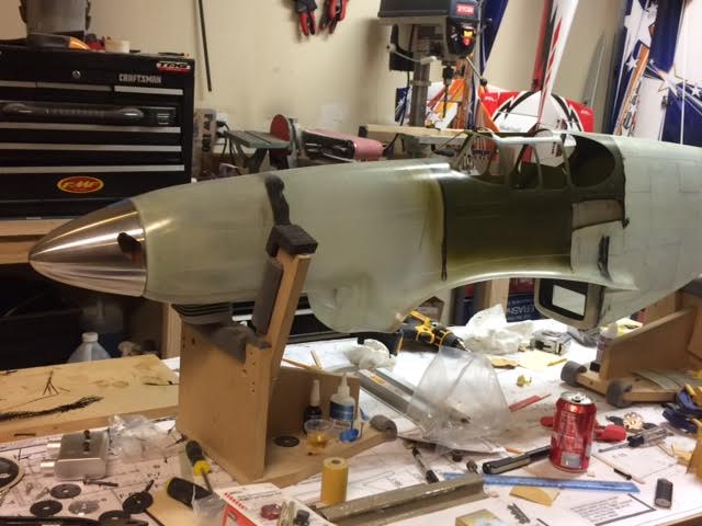
Pulled the motor to glass in the front and back of the firewall after the CF strands


Just a bit more progress...
Spinner showed up so I installed it to check alignment and fitment. Perfect fit! It's a Dave Brown 5.5
Pulled the motor to glass in the front and back of the firewall after the CF strands
Last edited by propwashed; 10-20-2016 at 08:27 PM.
10-20-2016, 08:33 PM
#84
Thread Starter
My Feedback: (13)
Join Date: Oct 2003
Location: C/S CO
Posts: 730
Likes: 0
Received 0 Likes
on
0 Posts
Last edited by propwashed; 10-20-2016 at 08:35 PM.
10-21-2016, 09:00 AM
#85
My Feedback: (37)
You will need to remove the back part of the stab fillet and you will need space for the elevator linkage. Build the stab per plan as a single piece, remove the front root section (just forward of the leading edge fillet and cap it with 1/8th ply. This will make the stab narrower in the root section.
I don't remember taking pictures of this on my P51 but here is something very similar.


Elevator linkages, I always use 2 elevator servos setup for this size bird, I lost 2 planes because of single elevator servo setup and I have brought one home when one of the two failed. I would have lost more planes if I only use one aileron servo, but since there is two it has never happened (knock on wood), redundancy helps.

This linkage uses a thick brass tube on each elevator with 3/16 threaded rods soldered to it. It is center supported with G10 material. You only need enough opening behind the stab to get the linkages through and the ability to glue in the hinges for the elevators. Can cap later when all things are glued in.
I don't remember taking pictures of this on my P51 but here is something very similar.
Elevator linkages, I always use 2 elevator servos setup for this size bird, I lost 2 planes because of single elevator servo setup and I have brought one home when one of the two failed. I would have lost more planes if I only use one aileron servo, but since there is two it has never happened (knock on wood), redundancy helps.
This linkage uses a thick brass tube on each elevator with 3/16 threaded rods soldered to it. It is center supported with G10 material. You only need enough opening behind the stab to get the linkages through and the ability to glue in the hinges for the elevators. Can cap later when all things are glued in.
Last edited by fw190; 10-21-2016 at 09:13 AM.
10-21-2016, 09:19 PM
#87
Thread Starter
My Feedback: (13)
Join Date: Oct 2003
Location: C/S CO
Posts: 730
Likes: 0
Received 0 Likes
on
0 Posts
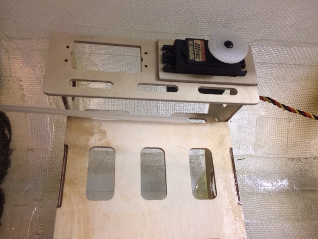
Tonight I cut a tank mount out of 3/32 6 ply on the CNC and glassed it in about 2" behind the firewall. These pieces are not part of the wood kit supplied with the Bob Holman kit. As a matter of fact I could not locate any formers or tank tray. I could be wrong though. Didn't spend too much time looking through the box of wood. The tank will fit in the tray and be secured with velcro straps. I'm using a 24oz Dubro. On each side of the tray will be the servo mounts for throttle and choke. While waiting on the resin to cure, Big Rob stopped by and we cut some custom parts for his F-15 Turbine build.


 Rob's F15 UAT tray
Last edited by propwashed; 10-22-2016 at 06:59 AM.
10-22-2016, 05:59 PM
#90
Thread Starter
My Feedback: (13)
Join Date: Oct 2003
Location: C/S CO
Posts: 730
Likes: 0
Received 0 Likes
on
0 Posts
So I ditched flying today so I could keep working on the build. Kinda windy anyway.
Cut a servo tray for choke and throttle:

 CF strand and epoxy resin to fuse
Figured I would tackle the cowling mounting system. Pretty much spent the whole day working on this. Started by installing the chin cowl and ensuring a good fit. Taped it into position then marked the scale location of the fasteners below the panel line. Then drilled 1/32" dia holes at the locations. then I cut a bunch of small ply washers with a 5/16" id and a 5/8" od. I also made the same size OD disks to use a a backer. These are to be mounted mounted in the fuse.


I then removed the chin and chased the 1/32" holes to 5/16" making sure not to let the bit wander off center. Then prepped and glued the washers with backer disk into the fuse sides centering them on the hole. ***I'm only doing 5 holes per side ***. The other holes will work only as guides for non functioning screws. These disks also got some CF strand and resin.
Also cut some 1/4" od x 3/32" hard ply tabs with a 1/32" pilot hole. Using the pilot holes for centering/reference, these glued to the inside of the chin cowl. They will align and hold the chin cowl into the fuse side holes and allow me to flush in the mounting screws.


I will be using small tapered head phillips screws for attachement.
Cut a servo tray for choke and throttle:
Figured I would tackle the cowling mounting system. Pretty much spent the whole day working on this. Started by installing the chin cowl and ensuring a good fit. Taped it into position then marked the scale location of the fasteners below the panel line. Then drilled 1/32" dia holes at the locations. then I cut a bunch of small ply washers with a 5/16" id and a 5/8" od. I also made the same size OD disks to use a a backer. These are to be mounted mounted in the fuse.
I then removed the chin and chased the 1/32" holes to 5/16" making sure not to let the bit wander off center. Then prepped and glued the washers with backer disk into the fuse sides centering them on the hole. ***I'm only doing 5 holes per side ***. The other holes will work only as guides for non functioning screws. These disks also got some CF strand and resin.
Also cut some 1/4" od x 3/32" hard ply tabs with a 1/32" pilot hole. Using the pilot holes for centering/reference, these glued to the inside of the chin cowl. They will align and hold the chin cowl into the fuse side holes and allow me to flush in the mounting screws.
I will be using small tapered head phillips screws for attachement.
10-22-2016, 07:46 PM
#91
I use #6 countersunk machine screws into hardwood blocks in all of my engine cowlings. When you thread the blocks, don't run the tap all the way through. This will leave a tapered thread that is self locking. After all of the screws are done, remove them one at a time and countersink them with a standard countersink reamer. I only use 4 of these screws to retain each cowling. If, after long use they loosen up, a drop of thin ZAP on the threads will tighten them up and harden the wood threads.
10-23-2016, 08:35 PM
#93
Thread Starter
My Feedback: (13)
Join Date: Oct 2003
Location: C/S CO
Posts: 730
Likes: 0
Received 0 Likes
on
0 Posts
Spent pretty much the entire day riveting out the front half of the fuse. Some are a little deep and I'm going to redo a few.


Last edited by propwashed; 10-23-2016 at 08:38 PM.
10-24-2016, 07:31 PM
#96
Thread Starter
My Feedback: (13)
Join Date: Oct 2003
Location: C/S CO
Posts: 730
Likes: 0
Received 0 Likes
on
0 Posts
Started fitting the canopy windows this evening. I've decided to go with the Malcom hood. This will require some modifications/removal of some of the framework and some additional material to get it to look right and function.
The front windows are installed and masked for the duration of the build.
There will be enough material to make the rear side windows from the standard canopy's plastic. It has enough material for everything.If you order just the Malcom hood you would need to obtain some plastic for the rears. I will not be installing the rears for a while. I want to complete some additional details in the radio area.
Last edited by propwashed; 10-26-2016 at 01:40 PM.
10-25-2016, 06:30 PM
#97
I set up the first work table and laid out the fuselage plans. I then made a tracing of the root rib outline at the fuse side. I transfered the rib tracing to a piece of balsa sheet, cut it out and used the balsa's concave rib outline to check the same location on the hanger 9 Mustang's center wing section. It looks like a very close match. There is a small difference (gap) in a portion of the airfoil that will have to be corrected. I already have the correct light weight epoxy filler to use for the correction on the fuse wing root filets.
Buying a hanger 9 wing kit and adapting the mounting to mate the H 9 wing to the B model fuselage would save a lot of time in construction. The major parts to be built would be the horizontal stab and rudder. I haven't checked the H 9 parts for fit yet but I have spares that may work there too. The major other work to be done is mostly in the fuselage. The engine to use is another decision to make also . I have the retracts and receiver on hand, just need batteries, servos, and wheels.
We already know how the H 9 Mustang wing flies, the biggest difference between the wing plans and the H 9 wings looks like the flaps on the plans are a slightly larger chord. I would have to strip the H 9 wing covering off to glass it to match the fuselage finish. This could be a combination of parts that might get this new B model flying quickly.
10-25-2016, 09:10 PM
#98
Thread Starter
My Feedback: (13)
Join Date: Oct 2003
Location: C/S CO
Posts: 730
Likes: 0
Received 0 Likes
on
0 Posts
Very interesting. Are you thinking of going that route? Stripping and glassing the wing isn't really a big deal. Would you still build the Bates wing also? I suppose there would be some other mods needed too. Wing mounting locations??? and trailing edge mods near the root to mate with the fuse...
10-25-2016, 10:28 PM
#99
Had this in mind before I read of your build of this plane. I was considering building a larger B model using the Ziroli Fiber glass B model fuse. I have about reached my physical limit (bad back) with the planes I already have and was reluctant to go larger. When I received my first H 9 Mustang I was glad that I could step up to a little larger plane and not have to lift more weight. I compared the complete empty fuse of the H9 P-51 to the 3 other Top Flite fuselages that I have on hand and found that the TF parts were almost twice the weight
10-25-2016, 10:57 PM
#100
Looking at the H 9 wing that I have, it appears to be a close fit. I would install modified wing mounting bulkheads in the glass fuse. I checked the H 9 rudder against the JB plans, it looks identical in plan form. From the pictures of the B model fuselage I think that some structural reinforcement is needed to transfer G loads across the length of the wing chord. I have long considered the Comp ARF Mustang but have read of instances where the fuse section behind the firewall buckled when the plane nosed over. Several other glass-fuse warbird brands have also suffered this type of damage on a noseover. A long time ago I, and others, had tail flutter problems with the popular (at the time) F-16 ducted fan powered Byron Jet. The flutter was caused by the manufacturer glassing the female mold, then leaning the mold against the shop wall to cure overnight. Un-cured fiberglass can flow away from critical areas while the curing process is happening. The female molds needed to be rotated periodically until the resin sets to avold this.
I recently witnessed the total destruction of a Robart P-47. When I examined the failure point (the tail cone just in front of the tail group), it was obvious that the glass thickness in that area was inadequate for a 40 lb model. The thickness at the failure point was paper thin, allowing the rear fuse to flex in flight. The pilot had said that he kept having to re-trim the pitch for level flight. Instead of landing to check out the trim problem he retrimmed and continued to do aerobatics on the plane's second flight. Un-cured resin flow could have caused the crash.
I recently witnessed the total destruction of a Robart P-47. When I examined the failure point (the tail cone just in front of the tail group), it was obvious that the glass thickness in that area was inadequate for a 40 lb model. The thickness at the failure point was paper thin, allowing the rear fuse to flex in flight. The pilot had said that he kept having to re-trim the pitch for level flight. Instead of landing to check out the trim problem he retrimmed and continued to do aerobatics on the plane's second flight. Un-cured resin flow could have caused the crash.