


Jerry Bates P-51B Build "Hell Yes Let's Go!!!"
 11-15-2016, 07:34 AM
#151

Thread Starter
My Feedback: (13)

Join Date: Oct 2003
Location: C/S CO
Posts: 730
Likes: 0
Received 0 Likes
on
0 Posts
Great catches! regarding the wing mounting L.E key, Is is possible that the wing bolt location is intended to install farther forward due to the fiberglass fuse and where the receiving block/former will install? I do not believe the LE bolt location is intended to be in the same exact location as on the actual drawings wood built drawings. I could be wrong however....
 11-15-2016, 08:36 AM
#152

No, using the the part as is would put one of the wing bolts almost in the fuse sidewall, and the other towards the fuse center. I have seen errors like this that may be linked to cad-cam software used to re-size drawings. Small details in the drawiings don't get put where they are supposed to be when the original drawings are enlarged. The error is not obvious until defective parts are made.
Another less obvious problem I have found is the length of the individual wing rib's trailing edge are different in front of the aileron. This is not as much of a problem, I just gently block sanded the long ribs down to the same as the correct length ribs, and added balsa shims to lengthen the short ribs. I assumed that the plan drawings are correct and adjusted each rib to the actual plan length. It did take some additional time to do this and I still have the other wing panel to also do these corrections to. I watched for any misinterpretation of the plans on my part that might make the other panel easier but so far it looks like the same fix is in order. One rib has a tab on it that is supposed to fit into a slot in the wing's trailing edge cap. Rather than cut the slot I just sanded the rib tab off. I have added balsa block reinforcements to the aileron hinge areas, the structure looks a little on the light side for my taste.
I remember scratch building models from plans decades ago that had much greater errors than these plans. With drawings as complex as these some errors are bound to crop up. Buying ARF models can be frustrating because the errors in construction are sealed up inside and require balsa surgery to correct. A case in mind is the H9 60cc P-51D wing tube misalignment that still has not been fixed.
11-15-2016, 06:49 PM
#153
Thread Starter
My Feedback: (13)
Join Date: Oct 2003
Location: C/S CO
Posts: 730
Likes: 0
Received 0 Likes
on
0 Posts
Gotcha, so you were saying the the hole spacing was correct however they were shifted off center line to one side. You are far ahead of me on the wing considering I'm determined to get all the mechanics worked out on the fuse prior to starting the wing. Not sure what retracts you plan to use however The Sierra tail retract is quite massive and takes up a lot of space in the fuse. It's nice but fairly bulky. You will need to keep the pushrods up as high as you can to allow for the steering arm to clear during retract rotation. I'm already redesigning my pushrods and will be mounting the rudder/steering servo up front as a pull-pull set up still working out the tailwheel steering. the plan shows the Sierra tailwheel folding all the way in and they do not do this. It does not complete the rotation cycle and end up level with the retract frame when up. there is much to work out to get everything correct and functioning between wheel and rudder control. I have already lightened the retract frame/housing to help with tail weight reduction.


Lightened housing
Lightened housing
Last edited by propwashed; 11-15-2016 at 07:44 PM.
11-15-2016, 08:22 PM
#154
I am using a set of air Robarts I have on hand. I will have to adapt the mounts to fit the Robarts but that won't take much work. The mains air cylinders have to be changed out to a set that will function in prop blast, the stock setup always stalls. After I have modified them they are 100% reliable. I like to get a new airframe to the point of checking the CG so I have to have the tail group completed, the wing and retracts done, and engine installation done so I can put the remaining equipment where it needs to be for best CG without ballast. After a new plane survives the test flight phase I begin to do the scale squadron markings and detail it. I don't like it much when I work a new plane up to the "finished" stage, then lose it early on. I don't finish details like the cockpit or the sequenced main doors until after 20 flights
are done sucessfully. Saves a lot of heartbreak.
My newest DA 60 is well broken in now and giving me amazing performance in the H9 D model, I may install it in the B model and buy another new DA 60 to break in for the H9 model. It is always nice to have a dependable engine in a new plane.
I had to put off further work on the Mustang, parts I ordered for my Vette came in so I have been deep into that all of today and part of tomorrow.
11-16-2016, 09:13 PM
#155
Thread Starter
My Feedback: (13)
Join Date: Oct 2003
Location: C/S CO
Posts: 730
Likes: 0
Received 0 Likes
on
0 Posts
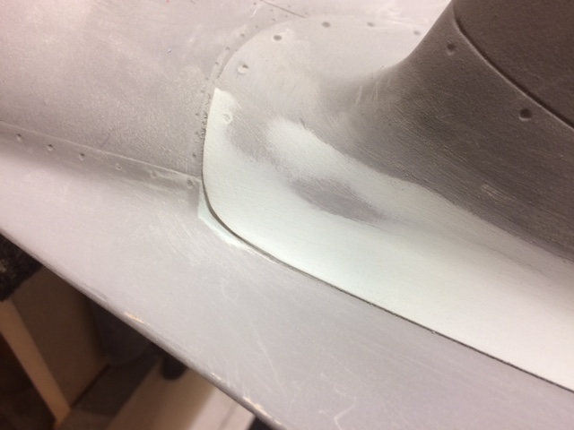
Continued working on the tail wheel install. The plans call for the servo to be installed behind the tail wheel which would control rudder and wheel steering. I plan on installing the servo up front with the elev servos so I'll still need to install a pull pull swivel control horn behind the tail wheel assembly for proper steering and to allow the cables to loose tension in the correct direction when retracted. I also went ahead and removed the fuse bottom behind the tail wheel for better access during installation. I may make this a removable panel for maintenance. I also had to redo the push rods to clear the tail wheel steering arm. They are now 1/4" OD hollow CF rods w/ a short run of 4-40 wire to the elev's and servos. The wire was soldered into a slip fit brass sleeve to take out any slop in the cf rods. the sleeves were then roughed up and notched a bit then epoxied into the rods. The guide holes I drilled at the top of the former keep them very stable. As you can see, the cf cloth at the stab to fuse fillet is pretty ugly however it was done by reaching through the rear of the fuse prior to deciding to remove the bottom. Ugly but strong never the less. It will look great when you can't see it! .
.


.
11-17-2016, 07:56 PM
#156
Thread Starter
My Feedback: (13)
Join Date: Oct 2003
Location: C/S CO
Posts: 730
Likes: 0
Received 0 Likes
on
0 Posts
Started roughing in the tail wheel doors and getting the mechanics worked out. I plan on installing the air cylinders up near the servo bay and using pushrods to engage the bell cranks that are fixed to the fuse sides. These are just rough at this point. The detailing will come later.


 .
.
11-19-2016, 02:38 PM
#157
Thread Starter
My Feedback: (13)
Join Date: Oct 2003
Location: C/S CO
Posts: 730
Likes: 0
Received 0 Likes
on
0 Posts
Worked on the tail wheel doors a bit more. They're not perfect to scale obviously however they will add some decent detail when the doors are down.


I also went ahead and made a swivel arm for the rudder and tail wheel steering cables.


I also went ahead and made a swivel arm for the rudder and tail wheel steering cables.
Last edited by propwashed; 11-19-2016 at 02:43 PM.
11-19-2016, 07:39 PM
#158
I am building the right flap tonight. It is not easy to maintain the correct airfoil shape due to the balsa ribs being so soft and surrounded by much stiffer ply wood. If I had known it would be like this I would have cut substitute ribs out of air ply. The ply skins are springy and want to go a different way, they bend the balsa ribs instead of the ribs dictating the shape.
11-19-2016, 10:31 PM
#159
Thread Starter
My Feedback: (13)
Join Date: Oct 2003
Location: C/S CO
Posts: 730
Likes: 0
Received 0 Likes
on
0 Posts
I've had similar problems before as well on other builds. I would wick some thin CA around the sides of the balsa and it will stiff'n it up to prevent it from warping or loosing shape.
11-19-2016, 10:38 PM
#160
Thread Starter
My Feedback: (13)
Join Date: Oct 2003
Location: C/S CO
Posts: 730
Likes: 0
Received 0 Likes
on
0 Posts
Got all the cables run to the rear. Took a little while to get the routing dialed in. I still need to run the short cables to the rudder from the rear swivel. Also made a custom pull pull arm for my rudder servo. Time to build the rudder and get the ass end of this bird buttoned up.


11-20-2016, 03:55 AM
#161
I have to use two servos for rudder and tailwheel steering to get the crosswind steering I have become used to. I set the rudder differential at 30% and the tail wheel at 85%. I limit the tailwheel to +-3% until the rudder is past 80%. This setup allows me to use large amounts of rudder to counter xwinds while the TW is holding the fuse straight down the runway.
11-22-2016, 02:24 PM
#164
Those dorsal filets had a very sharp leading edge. Also if you have already hard skinned the control surfaces, you can simulate fabric covering easily. Work on my Vette has consumed most of my day light hours but I was able to get the right flap sealed and sanded to final shape ready for glassing. I will try to get the ailerons built tonight.
11-23-2016, 01:11 PM
#166
Thread Starter
My Feedback: (13)
Join Date: Oct 2003
Location: C/S CO
Posts: 730
Likes: 0
Received 0 Likes
on
0 Posts
I've got some pretty good info on the fillet for reference. The forward starts fairly sharp and then starts to round over as it nears the dorsal. the sides almost blend with the edges of the dorsal. The end product with look very close to scale of the full size. I'm making a removable bottom fuse panel just in front of the rudder for access.
11-23-2016, 03:57 PM
#167
I wonder if the addition of the dorsal will be a noticable difference in flight. I have both "B" and "D" models and the "D" will wag its tail at high speeds, worse in turbulence. The "B" is solid tracking at all speeds. I think that the additional stability that the "B" model seems to have adds to its top end performance. My TF GS B is a little faster than a D with the same power, maybe 5-8 mph. The climb is certainly better, no bleed off of speed in a vertical climb.
I have begun to frame the left wing structure, have completed both ailerons and one flap. After buttoning up the right flap it became absolutely rigid, much stiffer than the flaps on my other P-51s.
The Robart air tail retract I have will fit with no mods except for an access hatch behind the doors. I have a Century jet tail retract that would need no access door but parts are hard to come by with that brand.
11-26-2016, 03:51 PM
#168
Thread Starter
My Feedback: (13)
Join Date: Oct 2003
Location: C/S CO
Posts: 730
Likes: 0
Received 0 Likes
on
0 Posts
I guess I'll find out on the dorsal because it has been added. I spent a couple of days creating the dorsal fillet and reshaping the top of the stab fillets which are different when the dorsal is added. I just used multiple layers of tape to build up the thickness and created a new edge and outline of the dorsal and stab fillets then used lightweight glazing putty as a filler. Also finished up the rudder and installed it. Then I installed the air cylinders and pushrods to run the rear gear doors they work great.


11-26-2016, 04:52 PM
#169
It looks like real nice work. I haven't had much time to work on my plane, the Vette is demanding attention and lots of money for parts. I try to work on the vette in the daytime and the B model at night. Tonight I just buttoned it up after dark, I'll have to do some electrical work on it tomorrow. I needed to buy some large clamps to hold the wing still while I work on the retract mounts and the wing leading edge, on the way a turn signal went out and I had to turn around and come back home to diagnose that problem. The RF turn signal light socket burned up and the emergency flasher switch stopped sending voltage to the light. You can't drive without turn signals, they like to ticket that.
11-26-2016, 05:59 PM
#170
Thread Starter
My Feedback: (13)
Join Date: Oct 2003
Location: C/S CO
Posts: 730
Likes: 0
Received 0 Likes
on
0 Posts
Thanks. What year Vette?
Also working on getting the elevators looking like they are fabric covered. I have a vinyl cutter and I was able to cut the scale looking tape to trim them out. I did the same on the rudder which I did cover with film prior to trimming it and priming it


Also working on getting the elevators looking like they are fabric covered. I have a vinyl cutter and I was able to cut the scale looking tape to trim them out. I did the same on the rudder which I did cover with film prior to trimming it and priming it
Last edited by propwashed; 11-26-2016 at 06:22 PM.
11-26-2016, 09:16 PM
#172
Your simulated fabric covering is a nice touch, a lot of the warbirds I see are overdone on the scale detail. If you look at a P-51 from a short distance like 50 feet, panel lines and rivets are barely visible. NAA did a lot of fine sheet metal work, the butt joints are hard to see. I see P-51 models that have deep panel lines, and raised rivets, especially on the wings. That much detail would only be visible on real planes that had the finish stripped off down to bare metal. Rivets are especially prominent on these models and the real plane's rivets were flush and ground level with the skin, then filled, sanded, and primed.
After the skin smoothing was done NAA applied a fast drying putty to the mid-chord point then sanded it again, finally painting the finish coat, (OD on most of the early planes, then silver paint on the later planes). Its my guess that NAA wanted their fighters to not only be better looking than the other manufacturer's planes, but faster too. The wing's underside fuel tank panels were the only area where fasteners were highly visible. I think they didn't want fasteners on the inside of the tank compartments rubbing on the tank bladders. On the top, the gun access panels were the only visible panel lines.
On the fuselage, the panels around the engine exhaust are prominent and I have found that adding thin aluminum duct tape does a real good simulation of these panels. I apply the tape, polish it, then scrape the metal grain lines in by using very fine steel wool front to rear only. The dzus fasteners can be done with a sharpened brass tube to make tiny rings followed by a small screwdriver tip pressed into the rings. Since the dzus fasteners were oriented in lines the screw driver slots should always be in the same direction.
11-26-2016, 09:30 PM
#173
Oh yeah, the Vette is a 98 C5 coupe automatic with a 2.73 to 1 rear axle gear. It was owned by one of my doctors since it had 1500 miles. It doesn't have the blazing accelleration that my old 67 convertible had with its big-block engine but it is a very nice riding car. On the interstate it does the speed limit with the engine at a fast idle, about 1500 rpm. On a long highway trip it gets 30 mpg. My 67 got 4-6 mpg around town and 10-13 hwy (Sunoco 115 octane). The doctor told me that he did 150 mph once, I won't be doing any of that.
11-26-2016, 11:03 PM
#174
Thread Starter
My Feedback: (13)
Join Date: Oct 2003
Location: C/S CO
Posts: 730
Likes: 0
Received 0 Likes
on
0 Posts
I have a Roland GX-24 vinyl cutter that I use for just about everything graphic related from decals to cutting masking film for painting.I just drew up the pattern and cut the simulated tape out of thin signage vinyl.