


Jerry Bates P-51B Build "Hell Yes Let's Go!!!"


 03-27-2018, 02:00 AM
#227

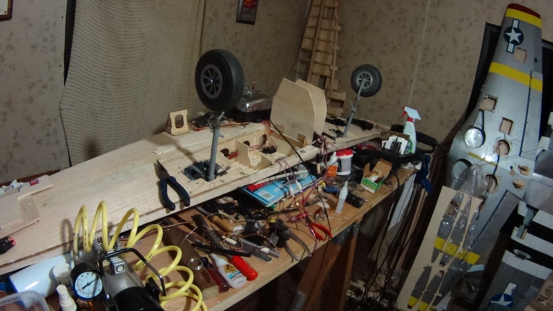
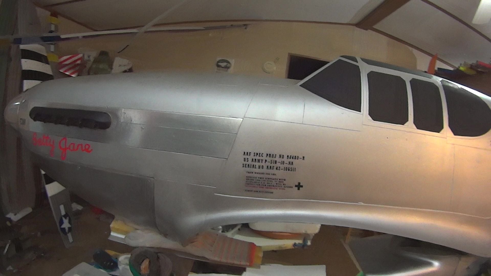
I finally got some time to work on mine, here are pics. All airframe construction is finished, Control surfaces are built and finish sanded ready for covering, Horizontal stab glassed and fitted, painted silver as is the fulll scale BettyJane. The DA 60 mounting is done and all internal fuse bulkheads carboned in place.
After building the wing I discovered an error in the wing root rib's location, the leading edge is about 1/4 inch to the right, too late to correct. The wing was built on the plans, so the error must be in the original plan's drawings. Irritating but I compensated during the wing mounting to the fuse, then sanded to fit. It all measures square so it is a minor beef. The glass fuse is a precision fit at the wing saddles, better than all of the ARFs I have owned so far. The vertical and horizontal stabs align square to the wing. I reinforced a lot of the parts installed already.
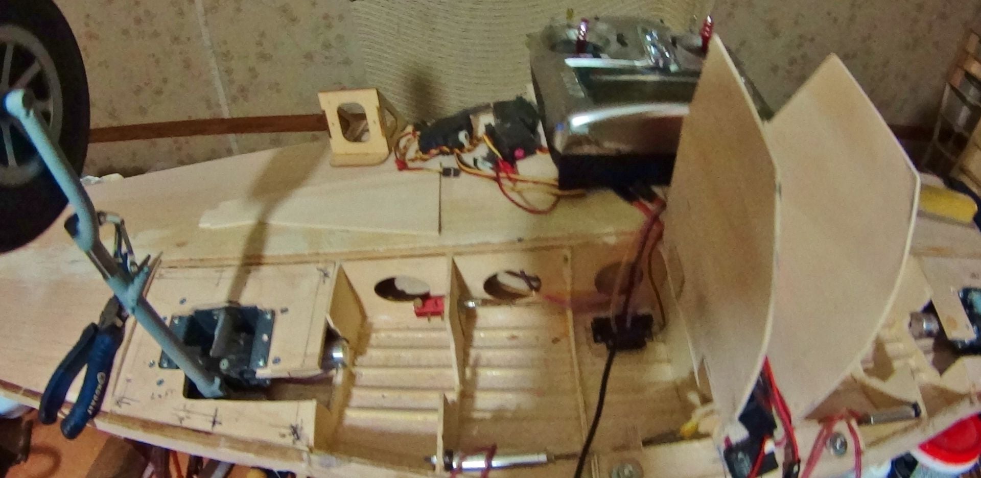
Since the wing will be glassed I didn't add anything to it except make the entire gear installation removable for future repairs. (bad landings, I ain't perfect). The entire retract control system is in the gear wells, only the tail gear is in the fuse with its own air valve and servo. It has two large air bottles in the fuse, only one air line to connect the wing. I used a 5 servo connector to connect the wing to the fuse radio, one connector to deal with at the field. As soon as I get this one flying I will dump the Top flights and all the parts I have on hand for them and order another JB Mustang, when I have the second plane flying I will dump the H9 Mustang too.
Any one building the glass fuse version should buy the compete wood kit, not the glass wood kit, which lacks a lot of fuse parts needed for the glass fuse. I am having to make fuse parts off the plans. I plan to have this plane flying during the summer.

After building the wing I discovered an error in the wing root rib's location, the leading edge is about 1/4 inch to the right, too late to correct. The wing was built on the plans, so the error must be in the original plan's drawings. Irritating but I compensated during the wing mounting to the fuse, then sanded to fit. It all measures square so it is a minor beef. The glass fuse is a precision fit at the wing saddles, better than all of the ARFs I have owned so far. The vertical and horizontal stabs align square to the wing. I reinforced a lot of the parts installed already.
Since the wing will be glassed I didn't add anything to it except make the entire gear installation removable for future repairs. (bad landings, I ain't perfect). The entire retract control system is in the gear wells, only the tail gear is in the fuse with its own air valve and servo. It has two large air bottles in the fuse, only one air line to connect the wing. I used a 5 servo connector to connect the wing to the fuse radio, one connector to deal with at the field. As soon as I get this one flying I will dump the Top flights and all the parts I have on hand for them and order another JB Mustang, when I have the second plane flying I will dump the H9 Mustang too.
Any one building the glass fuse version should buy the compete wood kit, not the glass wood kit, which lacks a lot of fuse parts needed for the glass fuse. I am having to make fuse parts off the plans. I plan to have this plane flying during the summer.
03-29-2018, 07:16 PM
#228

Join Date: Aug 2015
Location: Sandstone Point, Queensland, Australia.
Posts: 19
Likes: 0
Received 0 Likes
on
0 Posts
Hi Propwashed. Just wanted to thank you for taking the time to photograph your build, it really helps as I am a visual learner. I am about to rebuild a P51 which was a through away by a friend. I really enjoy building and watching your build has been a great tutorial. Looking forward to seeing you complete it as well as the maiden. All the best from Down Under. Mal
04-01-2018, 10:49 PM
#229
I was going through my supply of parts and materials looking for suitable stuff to make the outer gear doors from. I lucked out finding three sets still in the bags of molded fiberglass doors left over from earlier TF models. I guess I used the same set of doors on each new plane that replaced crashed planes. They are the exact size needed for the new plane, will save me many hours of work. It took about an hour to hinge the first door. the airfoil type is slightly off but almost unnoticeable. And on the wing bottom, will not be detectable. The TF planes don't use inner gear doors so I can't get those from that source, but the JB P51B plane's gear door is only slightly curved and is easy to make from air ply. It is too bad the TF gear door set is a part of the replacement wing set, too expensive for just the doors.
04-02-2018, 12:41 AM
#230
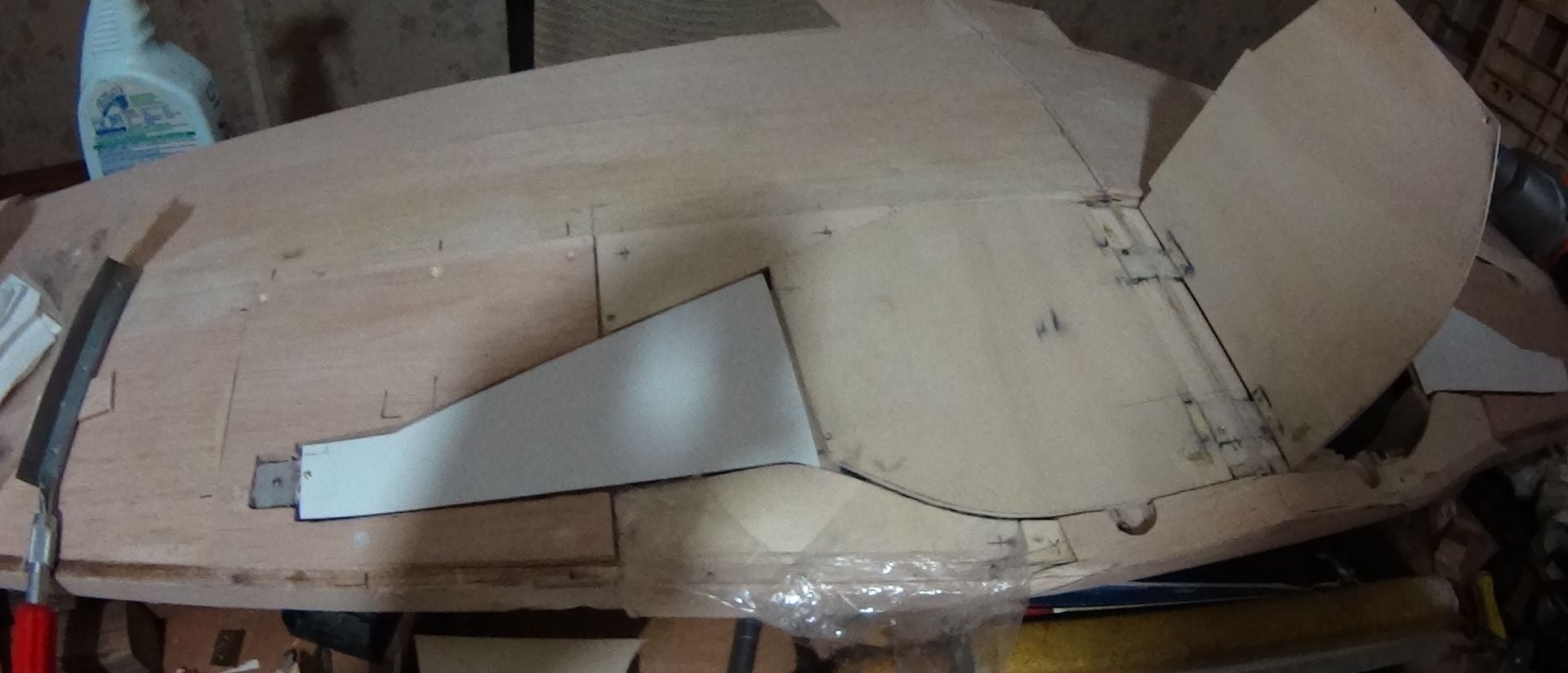
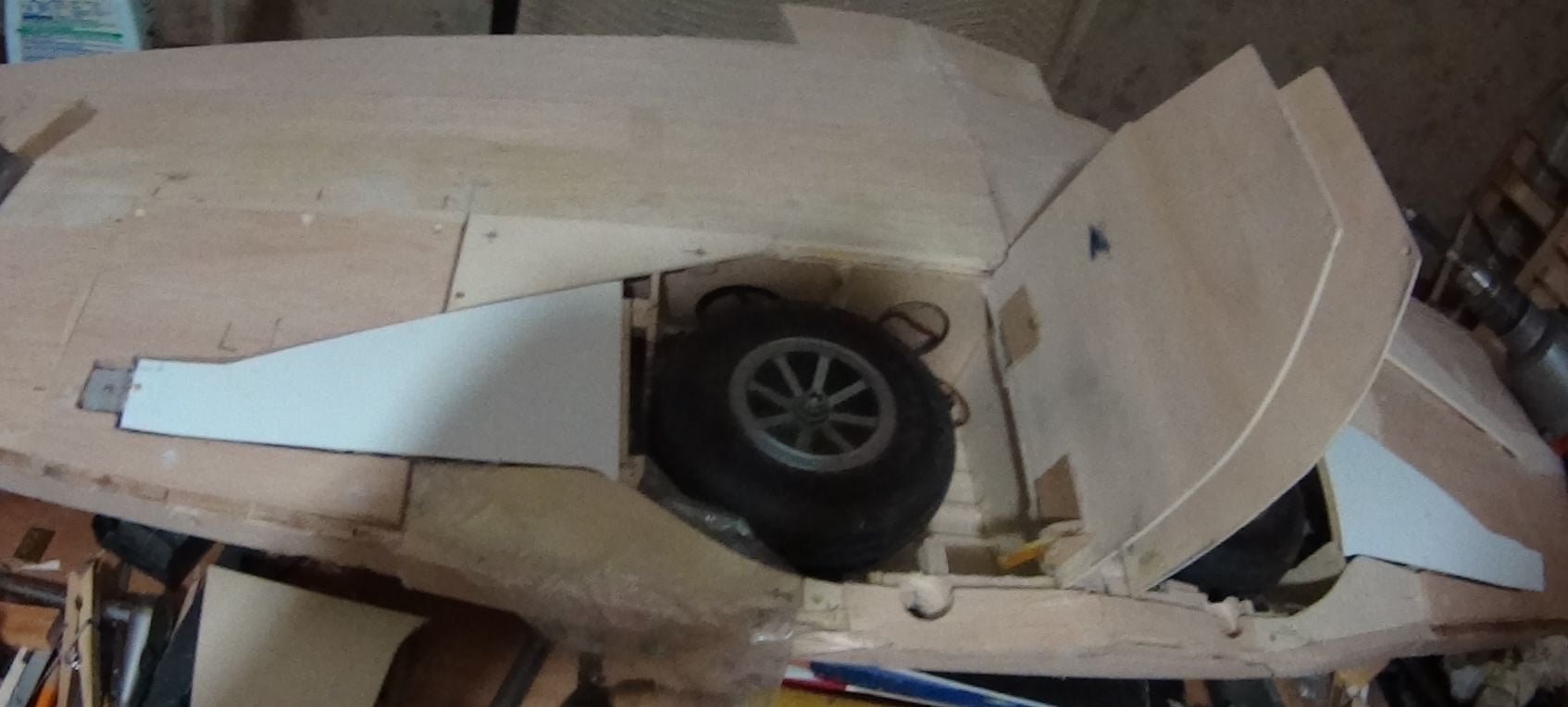
Posting some pictures of the Top Flight ARF P51D outer gear doors being installed on the JB P51B wing.
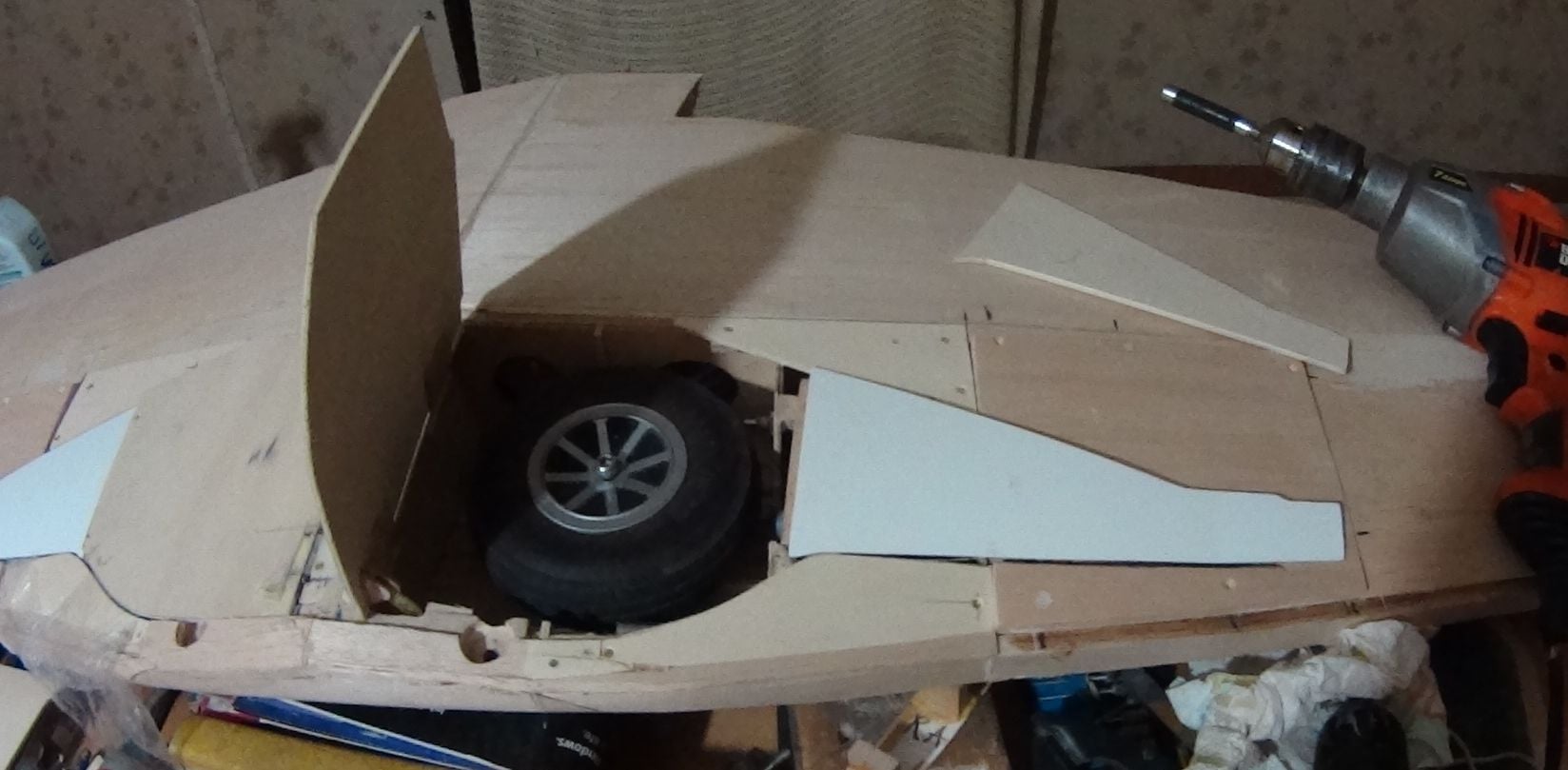
After deciding to do this, the actual mods and installation of the l/h door took a couple of hours.
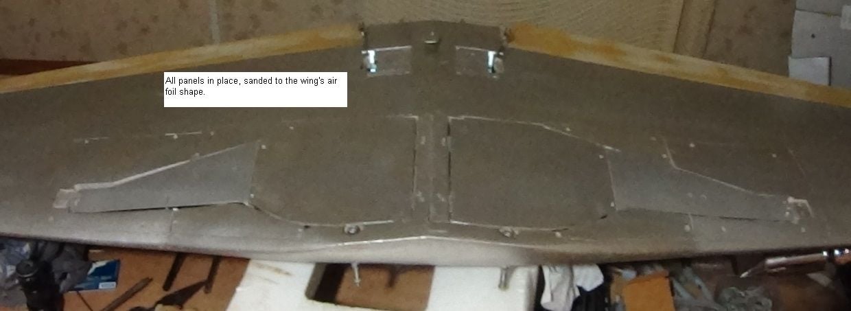
The air ply gear panels will have balsa sheet glued on to make the final shaping and sanding easy.
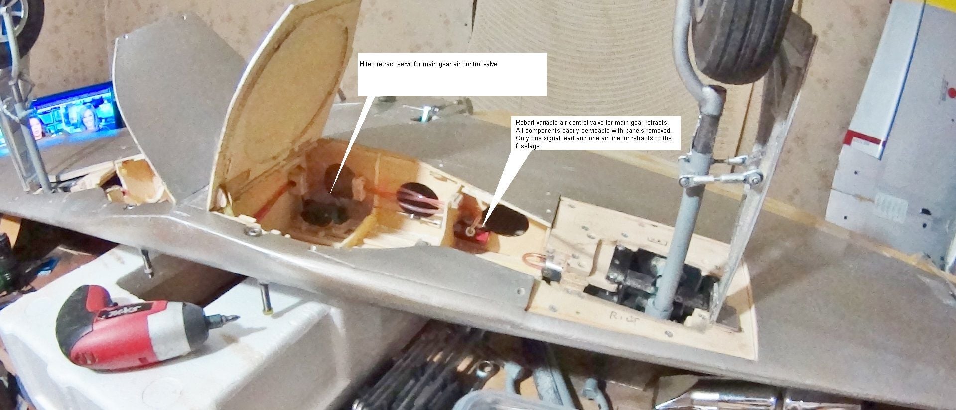
My design requirement is to make the whole retract installation accessible for adjustment and possible
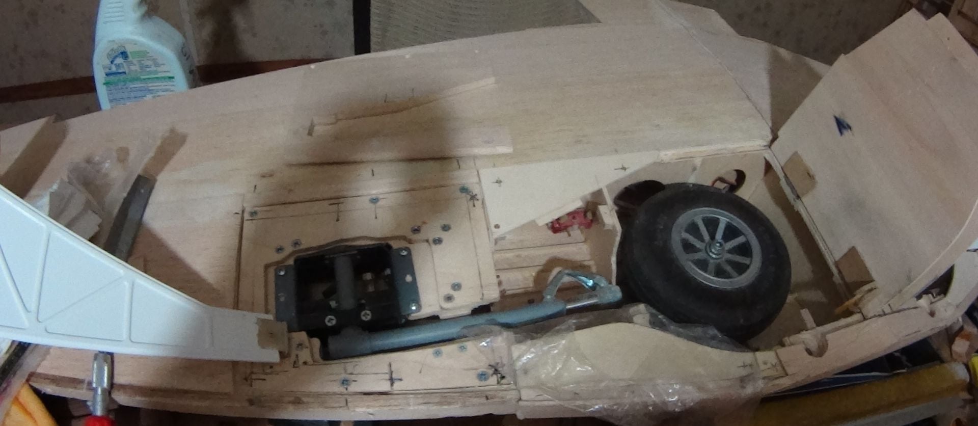
bad landing repair. The part that is most often damaged is the ply mount that the gear frame is attached to, in this wing I made the actual gear mount a a ply plate mounted under the main mount. When I cut these pieces, I made extras, all from one piece that was supposed to fit both sides of the wing, Unfortunately, the wing plans are slightly different left to right. I could put the piece in the left side as cut, but it had to be slightly trimmed to fit the right wing. A minor irritation. I make several spares to fit the left wing then a couple more are modified to fit the right wing. Each spare is fitted to its wing, then the first piece actually installed for each side is used as a pattern to drill the screw holes.
If, as has happened at an event, I damage a gear frame and its ply mount, I can swap out the damaged parts for the spares I carry. These ply mount plates are screwed to massive hardwood blocks built into the gear wells. In the past, a ground loop would typically bend an outer strut tube, the gear frame might be bent or even cracked, and the wood screws be pulled. I always had spare gear parts, but if the wood mounts were damaged, my flying was over for that trip. This set up spreads the gear stress over a larger part of the wing structure, hopefully the damage will be limited to the gear and mount plates.
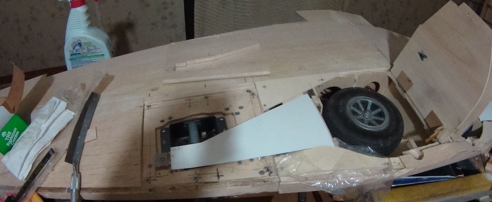
Since I started doing this type of repairable gear mount in my TF and H9 P51 models, I haven't had a single ground loop. I don't think my flying has improved, I give credit to a redesigned tail wheel retract gear and its mount, that actually prevents a ground loop as it tries to happen. This mod has worked for both fixed and retractable TW gear. The stock TF TW is designed to make a ground looping tendency worse, especially in crosswinds. Now, I do have to make steering inputs during TO and LDG, but it never tries to get away from me. All tail draggers are unstable in yaw on the ground unless the designer lengthens the rear fuse and increases fin and rudder area much larger than scale. I set the tailwheel castor and axle location to cancel side forces. The main wheels in the pictures are 5 inch, and will be changed to 5.5 inch before flight.
Last edited by sjhanc; 04-02-2018 at 01:30 AM.
 08-11-2018, 01:53 PM
#232
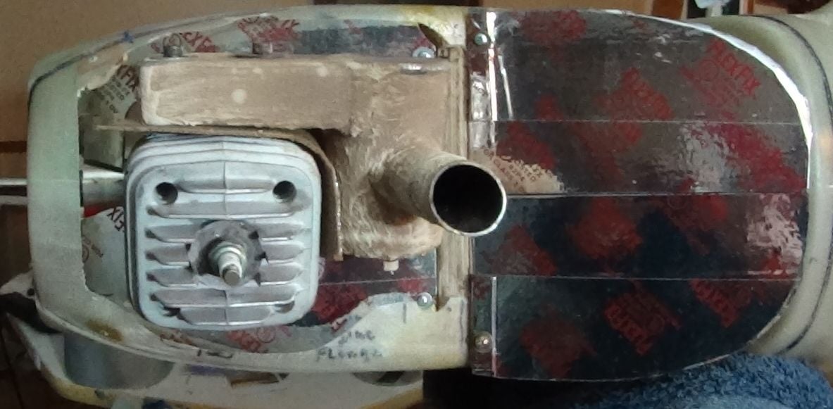
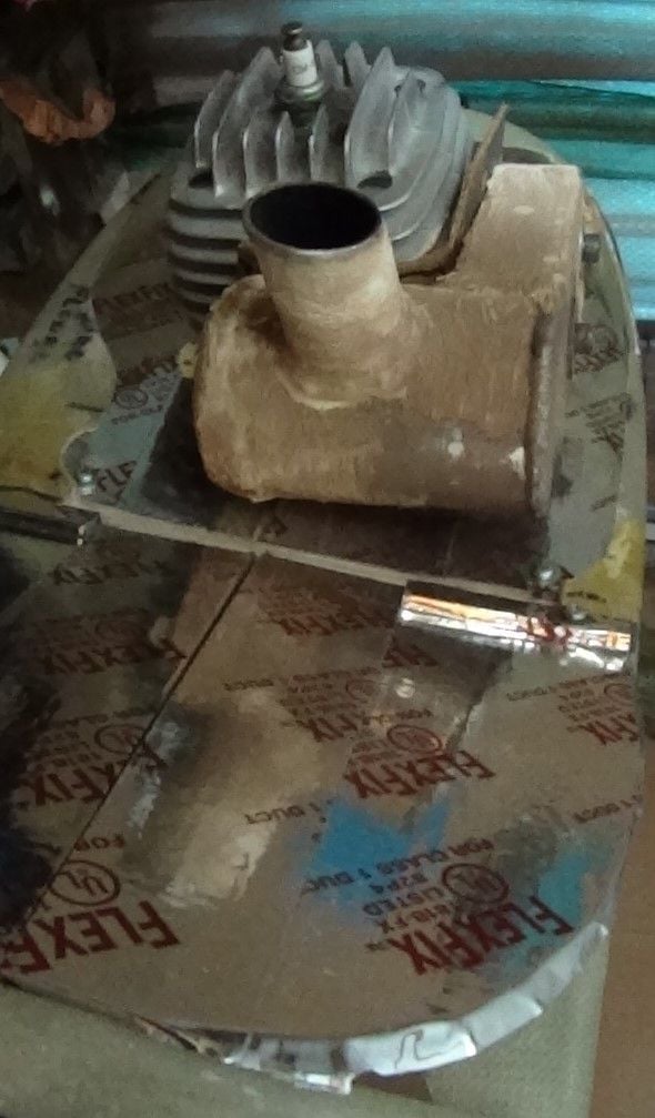
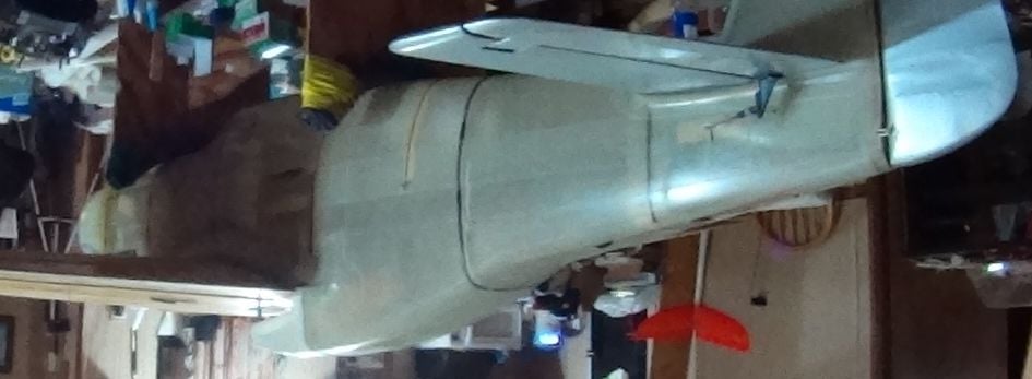
I made some more progress on the build, here are some pics. In the first two you can see the engine cooling baffles in their final configuration. Notice the baffle/gasket between the cylinder and the exhaust manifold. My brother has already used this in his Spitfire and reports it works good in that application. The baffle's purpose is to separate the radiated heat from the muffler, keeping it away from the cylinder just long enough for it (the heated air) to be behind the cylinder, and on its way out of the engine compartment before it can transfer any heat to the cylinder. Most of the chin scoop intake air is directed at the exhaust side of the cowling. Two more vertical baffles will be added behind the muffler to guide hot air out through an exhaust vent I will cut in the rear of the glass engine cover. This extra baffling has not been necessary in my two H9 Mustangs, but this new James Bates Mustang's engine compartment is long and has areas where stagnant air pockets might cause restrictions to air flow and build up of heat that can result in vapor lock. There is an open space under the exhaust manifold that is necessary for easy installation of the left hand baffle, another small piece will be added after the engine's final installation, but before the muffler is installed.
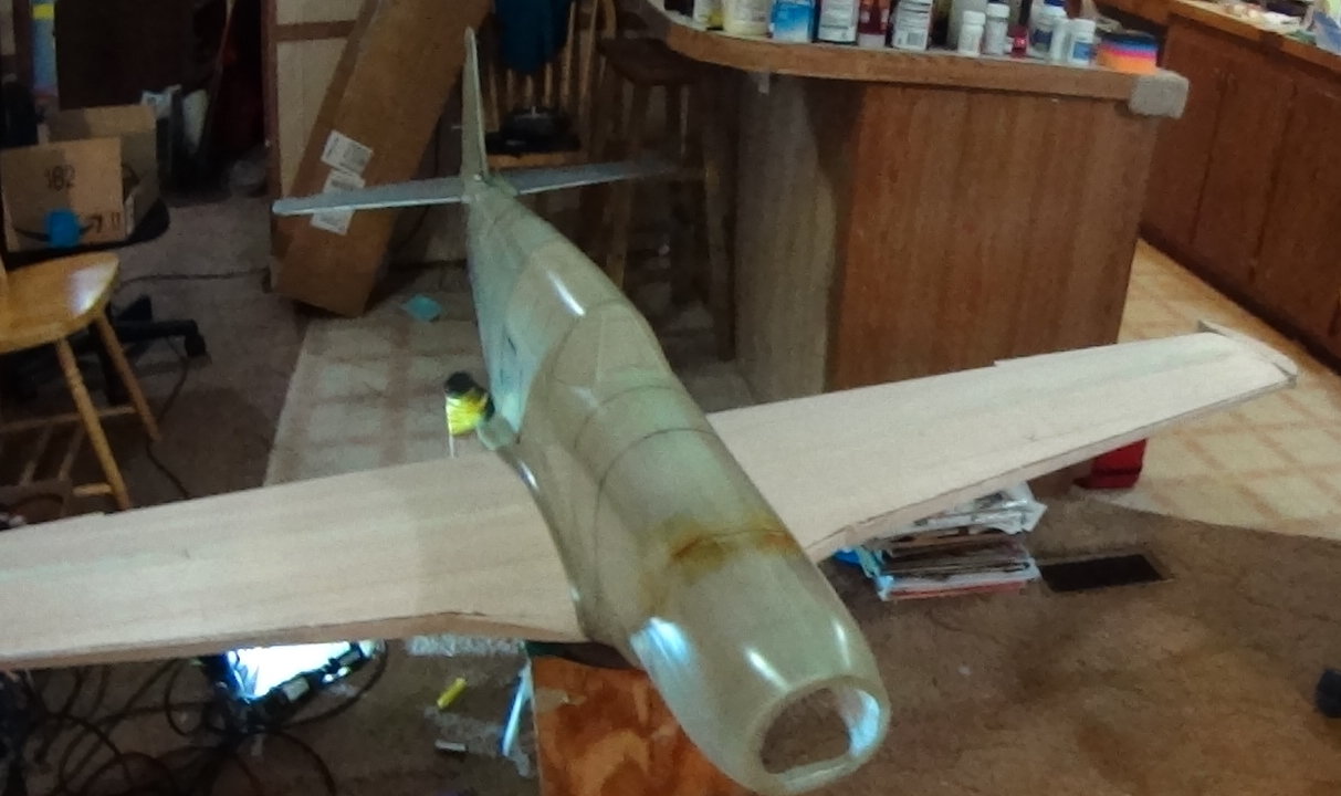
All of these baffles are keyed into grooves and slots with wood blocks to restrict movement in flight, they are captured by the cowing, and each is retained by a single wood screw into hardwood blocks. Foam insulating tape will seal all of the edges to prevent hot air leaks from going were they are not wanted. Sorry for the plain appearance of the airframe, it has always been my practice to get my scale planes into test flight and work out the flight trim and any problems that show up during the first twenty or so flights, then I begin adding the scale detail and squadron markings after each subsequent flying session.
I got tired of spending a lot of time finishing the plane first, then losing it to some unpredictable cause. I transfer engine and radio equipment that came from my current flyable Mustang, all new, flight tested, and broken in, into a new plane to ensure reliability. Just loading a new airframe with brand new equipment will not guarantee reliability, I have lost several planes on their first day to manufacturing defects in new flight pack components and to engines that shut off suddenly on takeoff. Since switching to DA engines my reliability has been nearly 100%, the only exception was caused by a spark plug insulator with a split that allowed arcing to ground and a misfire.
The airframe with a completed wing and all equipment bolted on the the fuse with covered tail surfaces and the engine and muffler installed balances on the CG and weighs 18 pounds. Adding the fuselage radio equipment , fuel, air systems, and finish should gross around 24 pounds. My H9 Mustangs both came out at 27 lbs 5 oz.
11-07-2018, 11:23 PM
#233
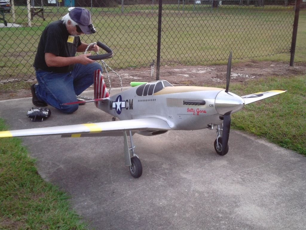
Some more progress, knocking them down as they come up. Invented a nose weight solution. Plane is almost ready to fly, still lots of detail to do as the test flights are completed. I usually plan on 20-30 flights for test and adjustment, then it will get a cockpit and detailing in the gear doors. This Mustang is my best project so far, if it is as much fun to fly as it was to build it will be the plane I wanted 65 years ago. And it is all good quality wood using REAL glue, no ARF stuff in this one.

 11-08-2018, 05:10 PM
#235
Thanks, I finally found the kill decals, put them on this afternoon. I will do another engine run tomorrow, and some shimming of the right landing gear to make the strut vertical. Then it is ready for first flight. Some of the squadron markings are in the mail.
Had to add 1 lb. of lead for the cg., weighs 26 lbs. now. I will do dzus fasteners on the engine cowls, but Mustangs had flush riveting on most of the panels, ground flush and sanded and filled, so no visible rivets on operational planes except for repairs that were improperly done. Only planes that were completely stripped of all paint and filler show rivets. Sunken rivet heads were NEVER used, and the only raised rivets were the high shear huck-bolts used to close the main fuel tank bottom panels under the wing.
Had to add 1 lb. of lead for the cg., weighs 26 lbs. now. I will do dzus fasteners on the engine cowls, but Mustangs had flush riveting on most of the panels, ground flush and sanded and filled, so no visible rivets on operational planes except for repairs that were improperly done. Only planes that were completely stripped of all paint and filler show rivets. Sunken rivet heads were NEVER used, and the only raised rivets were the high shear huck-bolts used to close the main fuel tank bottom panels under the wing.
Last edited by sjhanc; 11-08-2018 at 05:22 PM.
11-10-2018, 06:00 AM
#236
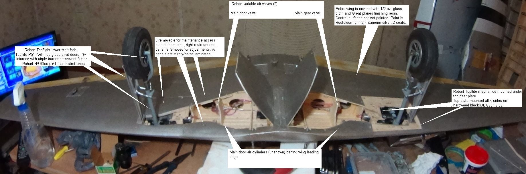
Some more progress pictures of the wing equipment installation. The fiberglass strut doors have molded reinforcement inner panels, not adequate to prevent flutter, they blow off in flight at relatively low speeds, necessary to add stiffeners. All individual retract mounting parts are standardized, I carry replacements to repair damage at the field. So far I have not had to use them. After I finish adding detail and weathering it will get a coat of semi-gloss clear to lock in the appearance.
11-10-2018, 06:14 AM
#237
I used a EMS/Jomar gear door controller after two others I bought from HK and another Hobby outlet were DOA. I don't think the Jomar controller is currently available, but they WORK. Since retiring my H9 Mustang for battle fatigue I have lots of equipment for this plane.
 11-10-2018, 12:17 PM
#239
I am going to use Rust-oleum satin clear so I can be sure it is compatible with the primer/silver I have already sprayed. So far, I like this paint, it looks like it is too thin when first sprayed but the flakes lay down nicely giving good coverage. One problem to avoid is runs, they have to be wiped off before they dry or they dry too slowly and get gummy. Hard to remove until completely dry, taking a week or more before they can be sanded off. Thin coats applied slightly wet work best, each coat can be sanded the next day, and the paint sands nicely with 320 grit finished with 4 ought steel wool to buff the shine off. Wiping with a tack rag removes the sanding dust leaving a whitish weathered look similar to actual planes in combat. Because it is primer also, defects can be filled and touched up, then sanded smooth before the next coat. Repairs blend in nicely.
A long time ago I did a jet with a similar finish that looked natural after the satin clear was applied, if it shines too much the gloss can be modified by buffing with the fine steel wool. You want SOME shine, just not too much. The Rustoleum seems to be mostly evaporating off, I used 5 cans so far, but the plane only gained one pound of gross weight. In sunlight it looks opaque but shining a really bright light inside the fuse you can see the light through the fiberglass and paint. I want a light finish for better performance and this is fine in the day light. The bright light doesn't show through both sides of the fuse so I am going with this stuff. Previous use of Topflite silver gives excellent coverage, and looks good but most of what is in the can stays on the plane for much higher weight gain. When buffing with steel wool I only wipe in one direction so it appears to be natural metal grain like real aluminum panels.
I considered doing an aluminum undercoat but don't want extra weight in the end. Besides, aluminum paint never looks like real aluminum on models. I wiped the glass fuse with acetone to remove mold release wax but the fuse has areas of too much mold release that when wiped leave pinholes to fill. The worst areas are the fiber glass windows that I painted flat black, full of pin holes but I will remove the windows later to install the canopy windows and cockpit. In hind sight it would have been better to use a stronger solvent to remove all of the mold release wax, when the spray paint solvents hit the mold release wax the two mix, producing fish-eyes that will not accept paint. Fortunately, these have been small areas to deal with.
I also applied metal panels to simulate the stainless engine cowling panels around the scale exhaust, these panels need simulated dzus fasteners that can be applied with a sharpened brass tube to make the circles and the slots with a jewelers screwdriver. I want to avoid the look of deep rivet holes on all the panels, P 51s in service never had deep rivets showing. North American stressed that the plane's skin should be smooth for best performance at high speeds. If you like rows of rivets showing on your model, do a P 40, ALL of the rivets show on Curtis products, and they were slow in combat. The same applies to Grumman planes.
12-15-2018, 09:09 PM
#241
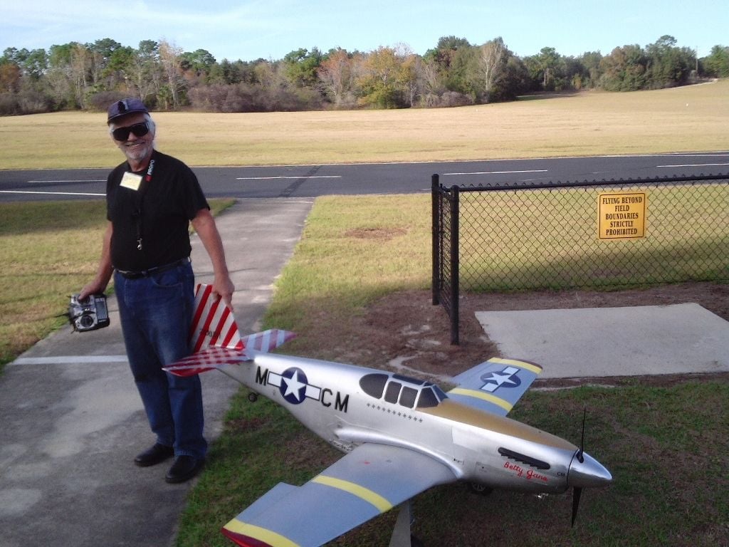
I have flown it 4 times now. I can report that it is a fine flying model, at least as good as the H9 P 51. The stall happens at about the same low speed as the H9 model with a slightly sharper break after it is forced to stall with the engine at idle and holding up elevator. Maneuvers are fast and smooth, I have done most of the maneuver list I use at scale events.
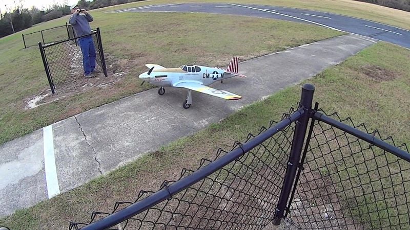
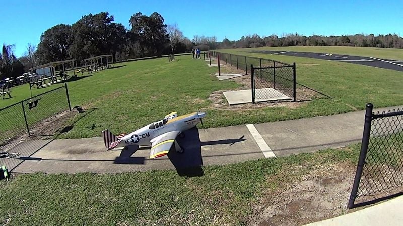
I took it out to fly about 2 weeks ago for a single test flight. It went well for the entire flight but got left gear mount damage when it hit a dirt mound (fire ants or lawn rats) on the roll-out in the grass. It was easily repaired with spare wood parts and a new upper strut tube, no actual wing damage. After an inspection finding no issues I got a break in the weather and took it out for a second flight a week later. This time I landed on the black top runway and the final landing was very nice. I quit after this flight due to cold cloudy weather late in the day.
At 26 lbs. plus fuel it is lighter than my other Mustangs and acceleration from slow speeds is quicker. It also holds its speed better during pull-ups to vertical flight or rolls, I can pull it over at the top for the dive, the others slow to almost stall speed, then I have to do a stall turn to come down. The take off run was long on the first flight, needing up trim to fly level. After it was trimmed the next take off was much shorter. The engine is still breaking in, its previous use in my other two Mustangs was not enough to finish the break in.
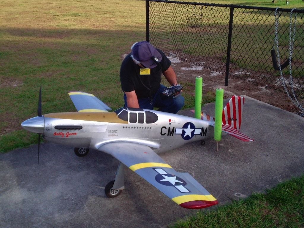
My engine cooling methods were refined for this plane, it is the cleanest I have done so far. No overheating issues were encountered after a ten minute + flight with 3 touch and go landings before the nice final to a full stop. It is winter in Florida now, opportunities for flying are only a few hours per week between cold fronts. The ambient temp on the three days I got to fly it was in the low 80 degrees cooling rapidly as the sun went down. My only complaint is the spark plug and its lead sticking out to spoil its profile. I have posted pictures of the engine cooling baffles in previous posts in this thread.
I was concerned about weight build-up when applying the glass finish so I didn't go for a completely smooth surface, a little of the glass cloth weave can be seen close up. I used Rustoleum titanium silver primer-paint for the final paint job, it is shiny when applied so I rubbed the shine off with 4-aught steel wool to flatten the shine on most of the model, some panels were intentionally left shiny for a more scale like finish. I will be starting another build of this model soon to do a better job on the final finish.
I balanced the plane on the plan's indicated CG, it is completely stable in flight but was slightly tippy on the runway running on the mains. I will experiment with CG locations, probably will move the cg back a little. I will do the cockpit and canopy when it makes it past 20 flights. I opened the throttle up on the third and fourth flights, the DA 60 rips the prop nicely, even in shallow climbs. I am using a Graupner carbon reinforced 22-12 prop. I think it needs a higher pitch prop for best performance. On a full throttle run and pull to vertical it did 4 1/2 rolls, 1 1/2 better than I could get with the T F and H 9 Mustangs. One of the last landings was the best I have ever done. The DA 60 rips the prop sooner, keeps ripping in level flight and into the pull-up. Acceleration from slow flight to high speed is very quick.
Another flight characteristic is not needing any rudder to track through turns or rolls. I do need to add more expo in the pitch and rudder controls. It is a little too sensitive to pitch during the take off and landing rolls.
I plan to post a video on you tube when I can stitch together all the different segments from the flying sessions.
I took it out to fly about 2 weeks ago for a single test flight. It went well for the entire flight but got left gear mount damage when it hit a dirt mound (fire ants or lawn rats) on the roll-out in the grass. It was easily repaired with spare wood parts and a new upper strut tube, no actual wing damage. After an inspection finding no issues I got a break in the weather and took it out for a second flight a week later. This time I landed on the black top runway and the final landing was very nice. I quit after this flight due to cold cloudy weather late in the day.
At 26 lbs. plus fuel it is lighter than my other Mustangs and acceleration from slow speeds is quicker. It also holds its speed better during pull-ups to vertical flight or rolls, I can pull it over at the top for the dive, the others slow to almost stall speed, then I have to do a stall turn to come down. The take off run was long on the first flight, needing up trim to fly level. After it was trimmed the next take off was much shorter. The engine is still breaking in, its previous use in my other two Mustangs was not enough to finish the break in.
My engine cooling methods were refined for this plane, it is the cleanest I have done so far. No overheating issues were encountered after a ten minute + flight with 3 touch and go landings before the nice final to a full stop. It is winter in Florida now, opportunities for flying are only a few hours per week between cold fronts. The ambient temp on the three days I got to fly it was in the low 80 degrees cooling rapidly as the sun went down. My only complaint is the spark plug and its lead sticking out to spoil its profile. I have posted pictures of the engine cooling baffles in previous posts in this thread.
I was concerned about weight build-up when applying the glass finish so I didn't go for a completely smooth surface, a little of the glass cloth weave can be seen close up. I used Rustoleum titanium silver primer-paint for the final paint job, it is shiny when applied so I rubbed the shine off with 4-aught steel wool to flatten the shine on most of the model, some panels were intentionally left shiny for a more scale like finish. I will be starting another build of this model soon to do a better job on the final finish.
I balanced the plane on the plan's indicated CG, it is completely stable in flight but was slightly tippy on the runway running on the mains. I will experiment with CG locations, probably will move the cg back a little. I will do the cockpit and canopy when it makes it past 20 flights. I opened the throttle up on the third and fourth flights, the DA 60 rips the prop nicely, even in shallow climbs. I am using a Graupner carbon reinforced 22-12 prop. I think it needs a higher pitch prop for best performance. On a full throttle run and pull to vertical it did 4 1/2 rolls, 1 1/2 better than I could get with the T F and H 9 Mustangs. One of the last landings was the best I have ever done. The DA 60 rips the prop sooner, keeps ripping in level flight and into the pull-up. Acceleration from slow flight to high speed is very quick.
Another flight characteristic is not needing any rudder to track through turns or rolls. I do need to add more expo in the pitch and rudder controls. It is a little too sensitive to pitch during the take off and landing rolls.
I plan to post a video on you tube when I can stitch together all the different segments from the flying sessions.
Last edited by sjhanc; 12-15-2018 at 10:09 PM.
 12-16-2018, 05:25 AM
#243
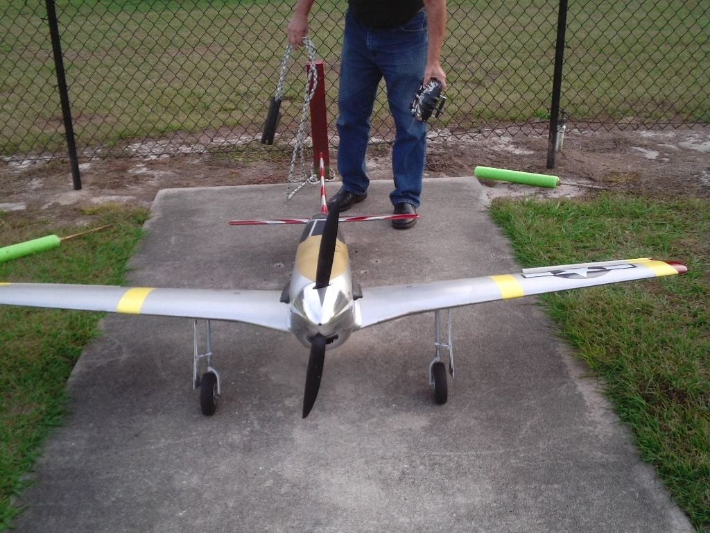
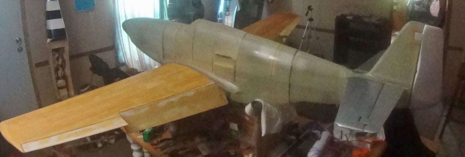
Up -loading a few more views. A clean front profile is evident in this picture.
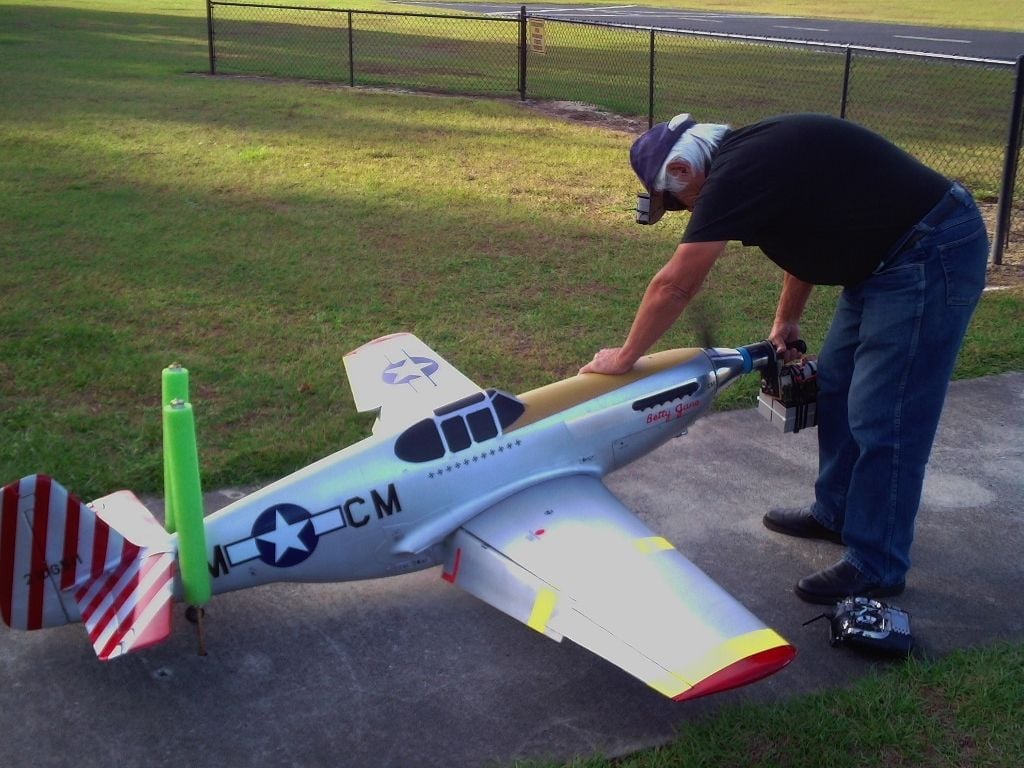
In this shot the engine installation is about as streamlined as is possible to do. It would be nice if DA would give us scale war bird guys an angled spark plug cylinder head similar to the Revolution R-50, which I considered because it is the engine the plans are drawn around. I just wanted a 60cc engine, I have a DA 50r, more than adequate and almost as fast in a P 51 as the DA 60, but the 50 is physically larger. Both the 60 and the 50 cc are faster than a T F P 51-B kit with a ZDZ 80 that I built over 10 years ago, that plane's climb performance is the only part of the envelope that was better than this plane's climb. Turning a 26-12 Zinger it would climb straight up from lift off. I attribute the top speed difference to engine installation drag, it was 29.5 lbs., causing the plane to fly at a higher AOA, more wing lift drag at the higher gross weight. The 80 engine stuck out into the slipstream more, another drag bucket.
The Revolution engine is a rear exhaust design, so canting the cylinder for manifold-to-cowling clearance is not necessary, with the right muffler it could possible offer better stream lining. I can't stress enough the need to isolate the carb and fuel lines from exposure to muffler radiated heat, the primary cause of P 51 models having a vapor lock issue and dead stick landings, usually off the runway. With this new plane I carried the engine cooling baffling further by making a baffle-gasket to isolate the cylinder from muffler heat. This is the first P 51 out of all the different brands that I have owned and flown that has not had early vapor lock issues and the resultant off-runway landings. I also use a parallel fuel filter in this plane because some of my engine loss-of-power issues were caused by tiny bits of debris in a fuel filter. One of the two filters can be completely clogged and it will still deliver full power.
12-20-2018, 01:55 AM
#244
I got one more flight in with this new plane last Sunday. I had noticed that the prop I had been using for the last two years (on 2 other P 51 models I own) had started to shake the plane. After changing the prop for a brand new (but unbalanced yet) prop I flew it, pushing the plane a lot harder than the previous flights. One thing was evident, this plane has the fastest top speed of any Mustang I have flown, with the exception of the electric powered P- 51 B fitted with a four blade prop that I retired for airframe cracks last year. I still haven't trimmed it for high speed flight, so there is more performance to be had with this airframe. I will need a prop with more than the 12 inch pitch that I am using now.
At 1/2 throttle or higher it sets up an incredible prop rip that it carries all around the flying field, very loud! The new engine may also be breaking in, putting out more power, but I still can't trust its idle yet. I am flying longer than 10 minutes per flight with no hint of vapor lock. I have a speed sensor installed in my H 9 Mustang, now that it needs crack repairs and I can't fly it I will move the speed sensor to the New JB Mustang.
At 1/2 throttle or higher it sets up an incredible prop rip that it carries all around the flying field, very loud! The new engine may also be breaking in, putting out more power, but I still can't trust its idle yet. I am flying longer than 10 minutes per flight with no hint of vapor lock. I have a speed sensor installed in my H 9 Mustang, now that it needs crack repairs and I can't fly it I will move the speed sensor to the New JB Mustang.
 12-26-2018, 01:44 PM
#247
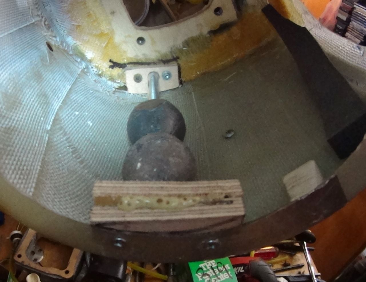
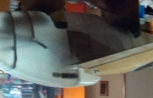
I don't have c/f servo mounts, I reinforced the joints everywhere they are bonded to the fiberglass with c/f strands. I got this stuff from the local hobby shop. It looks like a black rope that isn't twisted, wrapped around a piece of cardboard. After cleaning the joint area with acetone you apply a coat of epoxy to both sides of the joint, install the wood part, then saturate the c/f strands on a piece of flat cardboard with epoxy. Apply the c/f-epoxy strands to the joints and work it into the joint using an acid brush by tapping it, not brushing along the strands. When it sets up it makes a rigid filet that also stiffens the fiberglass. Before the fuse is painted the c/f can be seen through the fiberglass, verifying that the wood part is properly bonded to the glass. The acetone cleaning process, then rough sanding the joint area is critical for bond strength. Be sure the wood parts fit the inside of the fuse closely, but not tight enough to deform the surface of the fuse. In the picture above, all the bulkheads/formers are aligned with marker stripes drawn on the outside of the fuse, then glued in place.
Next, you add the c/f-epoxy strands around the glued areas against the wood parts. In the case of tapered fuse surfaces put the c/f on the larger side to trap the wood in place. Always do the harder-to-get-to areas first, working toward the large openings. Here, you can see the black lines of carbon fiber at each former/bulkhead.
 01-08-2019, 09:41 PM
#250
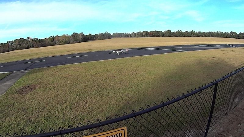
I have 12 flights on this plane now. The only issues were caused by me, plane is flying perfectly. I now have the control surfaces trimmed so that it does level flight hands off. I have never tried or planned to do 3 point landings with any of my Mustangs but this plane seems to settle into a 3 point attitude on its own, landings can be slow and touchdowns are soft with relatively short roll outs. My other Mustangs usually take the entire runway to stop, this one only needs half of the 600 foot hard top for a full stop. Other club members have noticed its performance, especially the slow take off and landing speeds and are asking a lot of questions about the plane. Its airframe is so clean that it cruises in the 90-100 mph range using about 1/3 throttle.
Keeping the ground runs straight is easy with little dabs of rudder. I have not yet moved the CG back so it is a little twitchy in pitch as the tail comes up, I have to be quick with elevator corrections, if it appears to rotate too much I pull the throttle back a little until it settles into the ground run on the mains. I plan to increase the elevator and rudder expo, also, a throttle curve to soften engine response is needed. It accelerates very quickly from stopped, once the tail is up takeoffs are a piece of butter cream cake. I enjoy every thing it does. Now that I have gotten rid of my H 9 Mustang and its spare parts I have room in my shop for another construction project, I will be ordering another batch of parts of this fine model very soon.
My new DA 60 is broken in and its idle has become reliable, I will buy another to break in for this plane and move the current engine and all of the radio gear to the new plane. Flight performance using the DA 60 is awesome, I have to pull the throttle way back to stop the prop rip produced by its Graupner PRO 22-12 propeller. I did another slow speed stall to check how quickly it recovers from the stall break. It gently lowered the left wingtip, as soon as I saw the tip drop I released the up elevator, added a little throttle and the stall recovery was straight ahead with little altitude loss.