


CY Model P-51D Mustang 2.4M - 85cc
 08-10-2017, 05:42 AM
#26

Thread Starter
By using a linkage rod with tape and a mark, I can check to see how well the motor is centred when exiting the cowl.
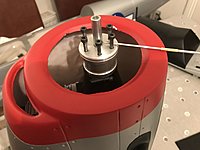
One problem I have is that the motor heads can only go so far downwards before hitting on the inside of the cowl. This is a tight fit considering its an 85cc engine in a 100cc model! I think it would be easy with a big single, but the extra length of the 2cyl makes it that little bit harder. Oh well hopefully it will be worth it.

One problem I have is that the motor heads can only go so far downwards before hitting on the inside of the cowl. This is a tight fit considering its an 85cc engine in a 100cc model! I think it would be easy with a big single, but the extra length of the 2cyl makes it that little bit harder. Oh well hopefully it will be worth it.
 08-18-2017, 02:32 AM
#27
Thread Starter
I measured out the engine mounting holes but a problem here is that the Roto engine mount system is very wide and not in an ideal place. I have put two pilot holes in place on the firewall so far, the third hole sits over the side wall so will require dremel work and the forth hole is out in open air. I also found that the Roto is setup for M5 mounting holes and I don't have any hardware on hand for that. I ordered some in and have also picked up some wood to make up the mount extension. So at the moment it's a waiting game, once I have the M5 hardware I can make a start on suring up the mount.
08-23-2017, 04:44 AM
#28
Thread Starter
I made up the mounting blocks to sit the Roto in place. There's still some reinforcing to do around this but just getting it to sit in place for now..

and also gluing in reinforcing plates to the back of the firewall to make sure the load is well spaced


I've drilled pilot holes for the mounting bolts but need to do some more work on them to align correctly and also glue in captive nuts. Fingers crossed I will get a look at that tonight!
and also gluing in reinforcing plates to the back of the firewall to make sure the load is well spaced
I've drilled pilot holes for the mounting bolts but need to do some more work on them to align correctly and also glue in captive nuts. Fingers crossed I will get a look at that tonight!


 08-24-2017, 08:08 AM
#30
Thread Starter
So far, so good,

Test fit. Cowl slides on and she fits!

The next couple of days will be reinforcing the box and cleaning it all up. I don't like the butt joint on the side mount so that will be either drilled and screw or maybe drilled and fowler with carbon rod to add strength to the joint. Lots of little tidy up things to do but I am over the moon it all fits
Test fit. Cowl slides on and she fits!
The next couple of days will be reinforcing the box and cleaning it all up. I don't like the butt joint on the side mount so that will be either drilled and screw or maybe drilled and fowler with carbon rod to add strength to the joint. Lots of little tidy up things to do but I am over the moon it all fits
 08-25-2017, 03:42 AM
#32
Thread Starter
08-26-2017, 05:54 AM
#33

My Feedback: (8)
By using a linkage rod with tape and a mark, I can check to see how well the motor is centred when exiting the cowl.
Attachment 2227548
One problem I have is that the motor heads can only go so far downwards before hitting on the inside of the cowl. This is a tight fit considering its an 85cc engine in a 100cc model! I think it would be easy with a big single, but the extra length of the 2cyl makes it that little bit harder. Oh well hopefully it will be worth it.
Attachment 2227549
Thanks Quandry
08-28-2017, 02:45 AM
#34
Thread Starter
looking good Quandry....I have a couple question on the Roto and the firewall, did you have to mount the engine at a slant because of the cowl? Also, What are the measurements of the bulkhead that the engine box is mounted on? I had the Roto 85 opposing twin a while back and it ran very well. I did have an issue with the exhaust valves sticking but that was fixed after I changed the oil that I was using....wonderful engine!
Thanks Quandry
Thanks Quandry
The engine box is mounted to a fairly cheesy sheet of ply. This will be glued and screwed to the thicker fues firewall, and the kit also inludes aluminium brackets to really screw the whole thing together. I hope then it should be rugged enough for the odd noseover that these planes are known for.
Good to hear your Roto ran well - fingers crossed I will have a similar experience
 08-30-2017, 08:07 AM
#35
Thread Starter
I cut and glued some carbon tube dowels to reinforce the engine mount

also using Hysol and injector filled gaps left over from the box cut and shut.

Then I sealed the wood with sand and seal and went with a thick coat of metallic black, and then some lacquer to seal it.

The kit includes two aluminium mounting brackets to hold the box firmly to the fues.

G
also using Hysol and injector filled gaps left over from the box cut and shut.
Then I sealed the wood with sand and seal and went with a thick coat of metallic black, and then some lacquer to seal it.
The kit includes two aluminium mounting brackets to hold the box firmly to the fues.
G
08-30-2017, 08:07 AM
#36
Thread Starter
I cut these in to four brackets as that suited the modified box a little better.

The plate is glued and screwed to the fues firewall with hysol and self tapping screws.


The screws are not removable in that process but it's ok there's no maintenance requirement to remove it.
The next job will be to install the rudder, from memory the kit was a little rough around that area so might need some finesse. Hope I'm up to the job!
The plate is glued and screwed to the fues firewall with hysol and self tapping screws.
The screws are not removable in that process but it's ok there's no maintenance requirement to remove it.
The next job will be to install the rudder, from memory the kit was a little rough around that area so might need some finesse. Hope I'm up to the job!
08-31-2017, 01:24 AM
#37
Thread Starter
I took a look at the rudder last night. Just a light dremel on the fues as it had some glue build up. Then I painted the back plane silver so any shadow gap will match the wings. Hopefully tonight I will be able to drill fit the hinges and glue home the fin itself so will grab some pics then.
I'm at the moment undecided on if I want to use the kit closed loop system or go with a direct attach rod. I normally prefer rod connections and I don't think the extra weight in the tail of one servo is going to be a problem...
I'm at the moment undecided on if I want to use the kit closed loop system or go with a direct attach rod. I normally prefer rod connections and I don't think the extra weight in the tail of one servo is going to be a problem...
09-01-2017, 05:12 AM
#39
Thread Starter
Thanks!
Weight wise I think it should be about 12-14 kg. I use Xicoy CG scales so will be able to come back later with a more accurate figure. I am up in the air about fitting a retracting tail wheel or not, that will likely have some impact on the final figure.
Weight wise I think it should be about 12-14 kg. I use Xicoy CG scales so will be able to come back later with a more accurate figure. I am up in the air about fitting a retracting tail wheel or not, that will likely have some impact on the final figure.
09-01-2017, 05:15 AM
#40
Thread Starter
Rudder is a built up surface that glues in to a composite piece with wood reinforcing blocks

So I painted the fues where it would attach, hardened the wood attachment points with thin CA.


G
So I painted the fues where it would attach, hardened the wood attachment points with thin CA.
G
09-01-2017, 05:15 AM
#41
Thread Starter
Greased the hinges with vas, and then glued it all home with Hysol.


A couple of small detail jobs to do later making the black band line up correctly etc but by adding some bright colour overall she looks good!
For the control horn I am going to cut it down to one side only and use a rod. Too many headaches with closed loop steering systems has left me jaded with using wires. I will put the horn on the same side as the exhaust ports so it leaves one good clean side for photos
G
 09-02-2017, 04:51 AM
#45
My Feedback: (13)
Thanks. Here is a real quick video. Mine is the gloss painted Reno style version so Im sure the lighter military painted version. Would be a small amount lighter. Plane flies awesome. https://youtu.be/qtzFLyoubZ8
09-04-2017, 07:13 AM
#47
Thread Starter
Thanks. Here is a real quick video. Mine is the gloss painted Reno style version so Im sure the lighter military painted version. Would be a small amount lighter. Plane flies awesome. https://youtu.be/qtzFLyoubZ8
09-04-2017, 07:13 AM
#48
Thread Starter
The Mustang comes with a closed loop kit for the rudder. Closed loop cable setups always drive me bananas so I decided to modify for a conventional rod system. Afaik external closed loop cable was not standard on P-51D anyway so it's not like I am losing a scale feature. Horns measured, cut, scuffed and glued in to place with Hysol. Next part is to paint the glue when cured and then plan out an internal servo mount...
Cut horns

Horns in place

Glued


G
Cut horns
Horns in place
Glued
G