


CY Model P-51D Mustang 2.4M - 85cc
 06-09-2017, 08:50 AM
#1

Thread Starter
Hi Folks, just starting a build thread up about my new project. This is a new direction for me as I'm mainly in to jets, but.... for many years I had always dreamed of having a Mustang and figured that this year I would just go for it. I'm not pushed on having anything 'super scale', so what I'm aiming for is sports scale and reliable Sunday flier.
Coming from jets, sound is important to me and while no 'model' engine can match the sound of the infamous Merlin I do want something that has a nice tone to it and not be like the "whipper snipper" style glow engines I used to fly years ago so I knew that I would have to go multi cylinder right out of the box. There is a balance point here though in that as soon as you go multi cylinder INLINE the price goes shooting up through the roof I would like to have got a 3cylinder but in honesty I found a good deal on a Roto 85FSi 2 cylinder so decided to go that way instead. I read that people complained the Roto does not have as much power as it should etc but I found a video of a CY Mustang fllying with the Roto 85 and it all looked (and sounded) roughly like what I was looking for so opted to bite the bullet. If needs be maybe I can upgrade to a 3cylinder inline in the future but there's a huge price jump for that one additional cylinder so...
The Roto presents very nicely, nice box and the engine looks great and comes with ignitors, instruction manual and basic open exhaust pipes.

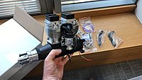
Coming from jets, sound is important to me and while no 'model' engine can match the sound of the infamous Merlin I do want something that has a nice tone to it and not be like the "whipper snipper" style glow engines I used to fly years ago so I knew that I would have to go multi cylinder right out of the box. There is a balance point here though in that as soon as you go multi cylinder INLINE the price goes shooting up through the roof
I would like to have got a 3cylinder but in honesty I found a good deal on a Roto 85FSi 2 cylinder so decided to go that way instead. I read that people complained the Roto does not have as much power as it should etc but I found a video of a CY Mustang fllying with the Roto 85 and it all looked (and sounded) roughly like what I was looking for so opted to bite the bullet. If needs be maybe I can upgrade to a 3cylinder inline in the future but there's a huge price jump for that one additional cylinder so...The Roto presents very nicely, nice box and the engine looks great and comes with ignitors, instruction manual and basic open exhaust pipes.
 06-09-2017, 08:56 AM
#2
Thread Starter
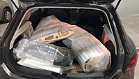
I ordered the P51 from bigplanes.nl, it took about a week to get from the Netherlands to Ireland and the box turned up in great shape. Pretty huge box though so I had to unpack everything in to my car - I found it was very well packed in a double cardboard wall box and bigplanes had included their own padding to make sure everything arrived without damage.
06-09-2017, 09:03 AM
#3
Thread Starter
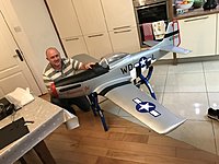
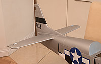
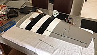
A buddy of mine called over to help with the model unpack, inventory, and check over and we had a great time exploring the kit. I was really shocked by the wingspan - 2.4m seems a bigger when you hold it tall!
hi

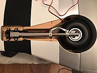
My wingman holding the model together on the stand for a quick shot. It looks more manageable like this.
Pretty much everything was good and everything is there. We did discover one issue though - I opted for the electric retracts bundle with the kit and it turns out that my oleos don't fit in to the 13mm Electron trunion correctly. I need to take off about .7mm to get them to slide home... bugger!
I made a start on grinding down the pins and it's looking good so far - hope to get them fully fitted tonight - wish me luck!
hi
My wingman holding the model together on the stand for a quick shot. It looks more manageable like this.
Pretty much everything was good and everything is there. We did discover one issue though - I opted for the electric retracts bundle with the kit and it turns out that my oleos don't fit in to the 13mm Electron trunion correctly. I need to take off about .7mm to get them to slide home... bugger!
I made a start on grinding down the pins and it's looking good so far - hope to get them fully fitted tonight - wish me luck!
06-12-2017, 02:13 AM
#4
Thread Starter
I managed to grind the pins down to a nice close fit, and then hand finished them with wet and dry - 400, then 600, then 800, then 1250, then 1500. They're still a little cloudy, and I am very tempted to sand them further and buff them with compound, but I'm also eager to get on with building the model. They fit nicely for now - might pretty them up later.

Starting on the kit, I grabbed a couple of servos and the elevator halves. In this kit I am using HS-5685MH (12kg) on the ailerons and elevators, Rudder and flaps will use HS-8335SH (25kg). Theyr'e all HV servos and can run straight off a 2s Lipo which simplifies things.

While CY have gone to a lot of trouble to make up the servo mount system, I took the opportunity to run around the edges with some thin CA just to make sure everything was sticking well. I also glue checked some joints in the elevator halves. Everything well glued on the bench, but with little knocks in transport or storage sometimes things can come loose - especially where the factory has been building for lightness. Thin CA is great for this because it seeps in to two wood halves and bonds as one chemical solid.

Starting on the kit, I grabbed a couple of servos and the elevator halves. In this kit I am using HS-5685MH (12kg) on the ailerons and elevators, Rudder and flaps will use HS-8335SH (25kg). Theyr'e all HV servos and can run straight off a 2s Lipo which simplifies things.
While CY have gone to a lot of trouble to make up the servo mount system, I took the opportunity to run around the edges with some thin CA just to make sure everything was sticking well. I also glue checked some joints in the elevator halves. Everything well glued on the bench, but with little knocks in transport or storage sometimes things can come loose - especially where the factory has been building for lightness. Thin CA is great for this because it seeps in to two wood halves and bonds as one chemical solid.
06-12-2017, 02:13 AM
#5
Thread Starter
Checking the control surface and factory drilled hinge holes with supplied hardware
I also CA hardened the back of the elevator and hing cut outs in the control surface. This gives a paintable surface which I lightly and quickly painted over with Tamiya Metallic Silver on a brush. The idea is that if the control surfaces are moved at the field you don't see wood in the gap. This kit is only 'sport-scale' so no need for too much effort here but I just prefer not to have wood showing on a WWII warbird that was made of metal.

The glue is drying on the hinges now so will continue with the build tonight...
I also CA hardened the back of the elevator and hing cut outs in the control surface. This gives a paintable surface which I lightly and quickly painted over with Tamiya Metallic Silver on a brush. The idea is that if the control surfaces are moved at the field you don't see wood in the gap. This kit is only 'sport-scale' so no need for too much effort here but I just prefer not to have wood showing on a WWII warbird that was made of metal.
The glue is drying on the hinges now so will continue with the build tonight...
Last edited by Quandry; 06-12-2017 at 02:20 AM.
06-13-2017, 03:42 AM
#6
Thread Starter
Hinges are dried on control surface so after touching up silver paint time for a dry fit and quick blip on the drill bit to make sure everything fits well.

The servo doors are predrilled, and included kit screws used to put in a thread to screw in to. This wood is all fairly soft though so afterwards everything hardened by wicking with thin CA

Plenty of control horns in the kit because it's all double horn with ball link. The glue side is smooth and the edges are rough but we need it the other way around. A bit of work required to prepare for install

The servo doors are predrilled, and included kit screws used to put in a thread to screw in to. This wood is all fairly soft though so afterwards everything hardened by wicking with thin CA
Plenty of control horns in the kit because it's all double horn with ball link. The glue side is smooth and the edges are rough but we need it the other way around. A bit of work required to prepare for install
06-13-2017, 03:45 AM
#7
Thread Starter
I'm going with a removable elevator setup. Using the kit hole I marked and drilled a screw hole in the rod, then installed a 30mm dowl rod in the pipe.

Underside of the elevator with holding screw installed. The second side is done after the first is finished to make a perfect finish.

Elevators screwed in place. Still more to do in this area but it's a good start!
Underside of the elevator with holding screw installed. The second side is done after the first is finished to make a perfect finish.
Elevators screwed in place. Still more to do in this area but it's a good start!
06-13-2017, 03:45 AM
#8
Thread Starter
I'm going with a removable elevator setup. Using the kit hole I marked and drilled a screw hole in the rod, then installed a 30mm dowl rod in the pipe.

Underside of the elevator with holding screw installed. The second side is done after the first is finished to make a perfect finish.
Elevators screwed in place. Still more to do in this area but it's a good start!

Underside of the elevator with holding screw installed. The second side is done after the first is finished to make a perfect finish.
Elevators screwed in place. Still more to do in this area but it's a good start!
06-14-2017, 02:50 AM
#9
Thread Starter
No photo updates today, but a quick summary from last nights activities:
I wanted to install a washer on top of the elevator retaining screw and found that below the covering was a captive thread. Checking in the kit contents I found sure enough that there is a pair of 3mm cap head bolts for the tail. This is a nice touch but not mentioned anywhere in the manual? :O
After looking at how it goes together I found that the idea is to put the aluminium tube through and then pinch the elevators to the rod. This will work, but it's not my ideal way of getting it to work. If the bolt rattles loose then everything can come apart. So I took some time to drill out my previous holes to a larger size and tapped the skin, so now the bolts screw down through the tail and in to the tube itself. Just a bit of gunging up the threads with locktite and everything should be secure for bolting on and off on flying days (hopefully!)
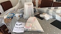
Other than that I also received some HobbyKing wing bags in the post, thankfully the Mustang wings fit the wing bags. You can squeeze two wings in to one bag, but it would be too tight to put in the wing joiner tube and elevators also so I recommend using two bags.
I wanted to install a washer on top of the elevator retaining screw and found that below the covering was a captive thread. Checking in the kit contents I found sure enough that there is a pair of 3mm cap head bolts for the tail. This is a nice touch but not mentioned anywhere in the manual? :O
After looking at how it goes together I found that the idea is to put the aluminium tube through and then pinch the elevators to the rod. This will work, but it's not my ideal way of getting it to work. If the bolt rattles loose then everything can come apart. So I took some time to drill out my previous holes to a larger size and tapped the skin, so now the bolts screw down through the tail and in to the tube itself. Just a bit of gunging up the threads with locktite and everything should be secure for bolting on and off on flying days (hopefully!)
Other than that I also received some HobbyKing wing bags in the post, thankfully the Mustang wings fit the wing bags. You can squeeze two wings in to one bag, but it would be too tight to put in the wing joiner tube and elevators also so I recommend using two bags.
06-14-2017, 02:53 AM
#10
Thread Starter
For anyone that is looking for the wing tote bags, these are the ones I went with and they work: https://hobbyking.com/en_us/hobbykin...-72-x-7cm.html
06-15-2017, 09:07 AM
#11
Thread Starter
I uncovered a captive thread in the tail plane and nice cap head bolt in the kit parts - no mention in the manual though?? still nicer than the screw system
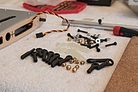
Ball links that come with the kit for included (but not pictured) rods, they look impressive at first site however I found two were cracked straight out of the bag. Think I'll get metal ones...

Standard horns are cut out of G10 and look to be ok. I cut them to size and roughened them up for gluing. The mounting plate to keep everything square is a nice touch.
[img]www.rcparkflying.com/rcpf/p51/DSC_4536.jpg[/img]
I used the mounting plate as a template to reveal the balsa

Ball links that come with the kit for included (but not pictured) rods, they look impressive at first site however I found two were cracked straight out of the bag. Think I'll get metal ones...
Standard horns are cut out of G10 and look to be ok. I cut them to size and roughened them up for gluing. The mounting plate to keep everything square is a nice touch.
[img]www.rcparkflying.com/rcpf/p51/DSC_4536.jpg[/img]
I used the mounting plate as a template to reveal the balsa
06-15-2017, 09:07 AM
#12
Thread Starter
I uncovered a captive thread in the tail plane and nice cap head bolt in the kit parts - no mention in the manual though?? still nicer than the screw system

Ball links that come with the kit for included (but not pictured) rods, they look impressive at first site however I found two were cracked straight out of the bag. Think I'll get metal ones...
Standard horns are cut out of G10 and look to be ok. I cut them to size and roughened them up for gluing. The mounting plate to keep everything square is a nice touch.
[img]www.rcparkflying.com/rcpf/p51/DSC_4536.jpg[/img]
I used the mounting plate as a template to reveal the balsa
06-15-2017, 09:08 AM
#13
Thread Starter
Filling the cut outs with Aeropoxy

horns glued down with ZAP. Once the aeropoxy goes off it will be a very solid setup

Breaking out the Tamiya silver to colour code the horns.

horns glued down with ZAP. Once the aeropoxy goes off it will be a very solid setup
Breaking out the Tamiya silver to colour code the horns.
08-02-2017, 05:22 AM
#15
Thread Starter
Sorry folks been a little while since I updated, I was away on vacation and only got a few sessions to sit down and look at the P51. Latest updates:
I found a couple of problems with the plastic control rod ends supplied in the kit (broken and super thin wall for ball link basically). Bit of a shame because it all looked comprehensive and very nice link rods. So I picked up some stuff from WMW warbirds (at Weston Park) that allowed me to make up the rod ends. I used some of the Blue fuel tubing from Bigplanes.nl to keep tension on the metal links as I figured it would work out nicer with the colour scheme.

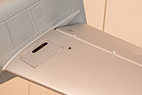
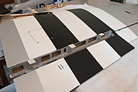
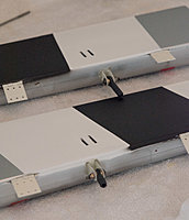
With the elevator halves more or less finished I turned my attention to the main wings. Firstly I sealed in the rear gap which were formerly just bare wood, and then painted with Tamiya Silver. I am not a fan of seeing wood on what should be metal planes and it would annoy me seeing the wood finish in there - even though it's mostly covered up with flap or aileron. So I just bit the bullet and did it. I am using 25kg Hitec 8335SH servos for flaps and 13kg Hitec 5685MH for ailerons. The 8335SH are compartively a much nicer servo but also a LOT more expensive so on this bird I'm just using them where serious torque is required (flaps and rudder).

The servo hatches are pre cut by CY Model, but you need to check the inner mounts, screw down the servos and cut out the control openings, hinge the control surface and glue in control horns. So it's a similar excercise to the elevators but doubled up due to flaps.
 ..
..
I found a couple of problems with the plastic control rod ends supplied in the kit (broken and super thin wall for ball link basically). Bit of a shame because it all looked comprehensive and very nice link rods. So I picked up some stuff from WMW warbirds (at Weston Park) that allowed me to make up the rod ends. I used some of the Blue fuel tubing from Bigplanes.nl to keep tension on the metal links as I figured it would work out nicer with the colour scheme.
With the elevator halves more or less finished I turned my attention to the main wings. Firstly I sealed in the rear gap which were formerly just bare wood, and then painted with Tamiya Silver. I am not a fan of seeing wood on what should be metal planes and it would annoy me seeing the wood finish in there - even though it's mostly covered up with flap or aileron. So I just bit the bullet and did it. I am using 25kg Hitec 8335SH servos for flaps and 13kg Hitec 5685MH for ailerons. The 8335SH are compartively a much nicer servo but also a LOT more expensive so on this bird I'm just using them where serious torque is required (flaps and rudder).
The servo hatches are pre cut by CY Model, but you need to check the inner mounts, screw down the servos and cut out the control openings, hinge the control surface and glue in control horns. So it's a similar excercise to the elevators but doubled up due to flaps.
08-02-2017, 05:50 AM
#16
Thread Starter
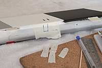
I decided to go for a smoother external finish and do an inboard mount on the flaps instead of the factory designed external mount. This involved trimming down the flap horns to fit from an alternate angle, using the dremel to burrow out a suitable slot in the flap..

And gluing them home with plenty of hysol inside to make sure everything is secure.
Prepping the wing for servos and 3mm connecting rods. Only one end of these is threaded so I broke out my tap and die set, cut them to lenth and then threaded the b end. I installed pre-centered servos so glued the ends to make sure everything was secure. They're not adjustable now but the surfaces are well set with my TX and I can use a click or two of sub trim if absolutely necessary.
The hatch covers do not sit that flush, so as a final fix I'll be going around and gluing in washers to make them all level - thanks for the tip to my wingman Jay!!

..
And gluing them home with plenty of hysol inside to make sure everything is secure.
Prepping the wing for servos and 3mm connecting rods. Only one end of these is threaded so I broke out my tap and die set, cut them to lenth and then threaded the b end. I installed pre-centered servos so glued the ends to make sure everything was secure. They're not adjustable now but the surfaces are well set with my TX and I can use a click or two of sub trim if absolutely necessary.
The hatch covers do not sit that flush, so as a final fix I'll be going around and gluing in washers to make them all level - thanks for the tip to my wingman Jay!!
..
08-02-2017, 05:50 AM
#17
Thread Starter
I decided to go for a smoother external finish and do an inboard mount on the flaps instead of the factory designed external mount. This involved trimming down the flap horns to fit from an alternate angle, using the dremel to burrow out a suitable slot in the flap..
And gluing them home with plenty of hysol inside to make sure everything is secure.

Prepping the wing for servos and 3mm connecting rods. Only one end of these is threaded so I broke out my tap and die set, cut them to lenth and then threaded the b end. I installed pre-centered servos so glued the ends to make sure everything was secure. They're not adjustable now but the surfaces are well set with my TX and I can use a click or two of sub trim if absolutely necessary.

The hatch covers do not sit that flush, so as a final fix I'll be going around and gluing in washers to make them all level - thanks for the tip to my wingman Jay!!
..
And gluing them home with plenty of hysol inside to make sure everything is secure.
Prepping the wing for servos and 3mm connecting rods. Only one end of these is threaded so I broke out my tap and die set, cut them to lenth and then threaded the b end. I installed pre-centered servos so glued the ends to make sure everything was secure. They're not adjustable now but the surfaces are well set with my TX and I can use a click or two of sub trim if absolutely necessary.
The hatch covers do not sit that flush, so as a final fix I'll be going around and gluing in washers to make them all level - thanks for the tip to my wingman Jay!!
..
08-02-2017, 05:59 AM
#18
Thread Starter
I then ran the internal wing wiring and mated this to TBolt connectors to make wings connections a breeze. The wings are quite large inside and I found the extension leads were prone to flop around a lot in there. I don't like to fatigue cables unnecessarily so I taped them on to a plastic guide tube and hot glued that to the inside of the wing. The cables do not move at all now, the wing is totally silent when flickign it back and forth in the air and also by snapping away the hotglue its easily removable for maintenance. Worked out a nice trick - unfortunately due to the darkness inside the wing I couldn't take a photo, might get one in the future though to complete the thread.
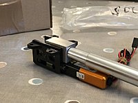
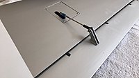
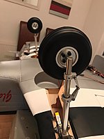
Next step was to get the bird to sit on her front feet. The electron ER40 retracts are an extremely close fit for the rails, but not close enough. Some light dremel work to remove 1.5mm from each side and the sit right on in there though!
This is just the first fit, I still need to connect the wire harness, cut out the retract tubs and come up with a way to fit the door legs. But it's a good start!

We used a piece of string and ruler to try and make the leg installation as symmetrical as possible. In the end it turned out pretty good, should look 'right' when sitting in the pits at the flying club
.
..
Next step was to get the bird to sit on her front feet. The electron ER40 retracts are an extremely close fit for the rails, but not close enough. Some light dremel work to remove 1.5mm from each side and the sit right on in there though!
This is just the first fit, I still need to connect the wire harness, cut out the retract tubs and come up with a way to fit the door legs. But it's a good start!
We used a piece of string and ruler to try and make the leg installation as symmetrical as possible. In the end it turned out pretty good, should look 'right' when sitting in the pits at the flying club
.
..

 08-08-2017, 05:21 AM
#21
Thread Starter
08-08-2017, 05:34 AM
#22
Thread Starter
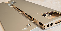
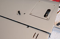
Getting back to my build log, I have more to do on the wings but the Roto motor is calling me so I decided to do some work on the engine mounting. First point of call then is fitting the cowl. The mounting system is bolts through the cowl in to preset captive nuts. The kit comes with a detachable plate, which I carefully lined up with the body and then screwed in to place. The accuracy here is not perfect (mine or the factories), so I also ran around the plate with a sanding drum to get it as close to 100% as possible. What I then noticed was that the cowl was an extremely tight fit and even started to split in some places. So again out with the Dremel sanding drum and running around the face of the mounting surface I was able to eliminate some high spots (and inside the cowl also) and then the cowl would slip on and off with a nice yet still tight fit.
In order to drill the cowl then I put marking tape on the fueslage, drew a straight line to each captive nut, made a measuring mark and noted the distance (in my case 40mm).
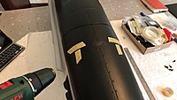
It's then just a matter of drilling the hole with the appropriate drill bit and then using the kit supplied fixings. Unfortunately 4 of my captive nuts had some glue inside the thread so I had to clean that out with a tap and die set, but with that little inconvenience aside everything else worked well.
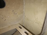
An additional issue did turn up though, after sanding down the cowl mounting surface it left some areas that needed filling because there wasnt a lot of glue in place for the firewall. After checking on the inside of the model you can see that there's not a lot of glue there (on my kit anyway):
So I mixed up some aeropoxy, and using a syringe pumped it in to the joint to get a nice thick seam
..
In order to drill the cowl then I put marking tape on the fueslage, drew a straight line to each captive nut, made a measuring mark and noted the distance (in my case 40mm).
It's then just a matter of drilling the hole with the appropriate drill bit and then using the kit supplied fixings. Unfortunately 4 of my captive nuts had some glue inside the thread so I had to clean that out with a tap and die set, but with that little inconvenience aside everything else worked well.
An additional issue did turn up though, after sanding down the cowl mounting surface it left some areas that needed filling because there wasnt a lot of glue in place for the firewall. After checking on the inside of the model you can see that there's not a lot of glue there (on my kit anyway):
So I mixed up some aeropoxy, and using a syringe pumped it in to the joint to get a nice thick seam
..
08-08-2017, 05:54 AM
#24
Thread Starter
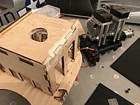
Next was to take a look at the engine..
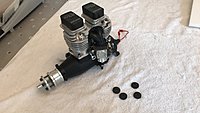
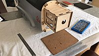
I dropped over to a buddy of mine who had some insulation mounts left over from a previous build. I therefore had everything required to measure the bird for the Roto...
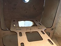
After checking the distance from the front of the mounting box to the outside of the cowl (allowing a 5mm shadow gap for the spinner) I then determined that I needed to cut down the box by 45mm to get the engine in to a good place. Depending on how close the spinner is when turning over the motor I may still need to shim it out a mm or 2 more but this is hopefully a good starting place.
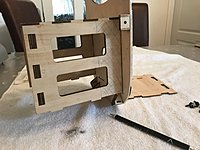
Looking closer at the mount plate I found that three sides of the box were glued in pretty well, so I had to drill them out to remove the box and then after measuring and marking all sides cut with a hacksaw. This was actually quite easy but then the hard part is reattaching the box in a sturdy way.
G
I dropped over to a buddy of mine who had some insulation mounts left over from a previous build. I therefore had everything required to measure the bird for the Roto...
After checking the distance from the front of the mounting box to the outside of the cowl (allowing a 5mm shadow gap for the spinner) I then determined that I needed to cut down the box by 45mm to get the engine in to a good place. Depending on how close the spinner is when turning over the motor I may still need to shim it out a mm or 2 more but this is hopefully a good starting place.
Looking closer at the mount plate I found that three sides of the box were glued in pretty well, so I had to drill them out to remove the box and then after measuring and marking all sides cut with a hacksaw. This was actually quite easy but then the hard part is reattaching the box in a sturdy way.
G
08-10-2017, 05:37 AM
#25
Thread Starter
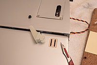
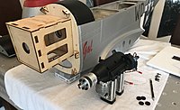
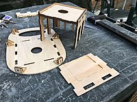
I've glued the box back together using dowls to re-attach to the back plate. So far it feels strong but I will do some good reinforcing after engine fitting which is likely to involve a good bit more cut n shut..
It's handy that the cowl/backplate can attach seperately to the fuz, useful for test fitting the heavy engine on the bench without having to hold it.

So far the indication is that the motor has to kick out to the right so I had to grind down the side rail on the box, again there will be re-inforcing carried out to compensate.
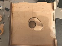
The idea is to sit the motor in place, fit the cowl, then move the motor by hand to its desired resting position, then you have to carefully remove the cowl and drill mounting holes. The markings on this plate help to sanity check the engine before drilling in case it moves slightly when removing the cowl. Note also that the centre hole had to be made a little bigger to facilitate a breather pipe on the Roto that protudes from the back - beyond the length of the engine mount.
G
It's handy that the cowl/backplate can attach seperately to the fuz, useful for test fitting the heavy engine on the bench without having to hold it.
So far the indication is that the motor has to kick out to the right so I had to grind down the side rail on the box, again there will be re-inforcing carried out to compensate.
The idea is to sit the motor in place, fit the cowl, then move the motor by hand to its desired resting position, then you have to carefully remove the cowl and drill mounting holes. The markings on this plate help to sanity check the engine before drilling in case it moves slightly when removing the cowl. Note also that the centre hole had to be made a little bigger to facilitate a breather pipe on the Roto that protudes from the back - beyond the length of the engine mount.
G