TopRCModel FW-190
 06-04-2020, 07:51 PM
#851

besides what is in post 95 in regards to showing rudder cable exits out the fuselage. Does anyone have a hard reference measurement that could be given so one could be successful in locating the proper exit point out the fuselage? Like measuring down from a stab tube location and then back to end of the fuselage skin.
thanks in advance!
thanks in advance!
 06-06-2020, 10:50 PM
#852
Member
Well here is my maiden with the right gear failing to come down due to it stripping itself out from testing on the bench.
All of you that said go air that I didn't listen to, sorry. I should have and not wasted 800. on getting electric motors fitted.
The motors were fitted to the brass piece that the air cylinder is normally fixed to. Except in this case they have the steel threaded shaft running in and out of the brass fitting. I should have known then that it was doomed.
I am now fitting the air system to it.
Power is a Leomotion 8038-140v2 10Kw (12hp) motor. 14,000mah 12S pack. Turning a 28/17 Ramoser Vario prop. Sound system turned off so we could hear any issues.
Weighing at a svelte 45lbs it flew beautifully.
https://www.youtube.com/watch?v=2w0b...qbbcYLRs7RLxmo
06-07-2020, 02:56 AM
#853
besides what is in post 95 in regards to showing rudder cable exits out the fuselage. Does anyone have a hard reference measurement that could be given so one could be successful in locating the proper exit point out the fuselage? Like measuring down from a stab tube location and then back to end of the fuselage skin.
thanks in advance!
thanks in advance!
Hi,
I made the hole 80mm from the end of the fuselage and 27mm above the underside (measusred on 80mm) of the fuselage.
06-07-2020, 04:29 AM
#855
Well here is my maiden with the right gear failing to come down due to it stripping itself out from testing on the bench.
All of you that said go air that I didn't listen to, sorry. I should have and not wasted 800. on getting electric motors fitted.
The motors were fitted to the brass piece that the air cylinder is normally fixed to. Except in this case they have the steel threaded shaft running in and out of the brass fitting. I should have known then that it was doomed.
I am now fitting the air system to it.
Power is a Leomotion 8038-140v2 10Kw (12hp) motor. 14,000mah 12S pack. Turning a 28/17 Ramoser Vario prop. Sound system turned off so we could hear any issues.
Weighing at a svelte 45lbs it flew beautifully.
https://www.youtube.com/watch?v=2w0b...qbbcYLRs7RLxmo
All of you that said go air that I didn't listen to, sorry. I should have and not wasted 800. on getting electric motors fitted.
The motors were fitted to the brass piece that the air cylinder is normally fixed to. Except in this case they have the steel threaded shaft running in and out of the brass fitting. I should have known then that it was doomed.
I am now fitting the air system to it.
Power is a Leomotion 8038-140v2 10Kw (12hp) motor. 14,000mah 12S pack. Turning a 28/17 Ramoser Vario prop. Sound system turned off so we could hear any issues.
Weighing at a svelte 45lbs it flew beautifully.
https://www.youtube.com/watch?v=2w0b...qbbcYLRs7RLxmo
06-07-2020, 04:32 AM
#856
Hi Jraucut,
I made a photo but because I'm new on this forum I am not allowed to send it.
Go to the horizontal position of 80mm starting from the end of the fuselage.
At that posistion, drop a vertical line until the line touches the underside of the fuselage. Then measure 27mm upwards.
The intersection point of this line and the 80mm horizontal line is the drill position.
Carlo
06-07-2020, 04:36 AM
#857
got it - thanks! So the flat of the bottom of fuselage up 27mm.
I'm planning to start adding some pics of my build, I'm getting close to the end of the build and now im finding myself staring at the plane more than working on it, lol.
I'm planning to start adding some pics of my build, I'm getting close to the end of the build and now im finding myself staring at the plane more than working on it, lol.
06-07-2020, 04:40 AM
#858
Can you show some pics of your build?
Carlo
06-07-2020, 04:50 AM
#859
 06-07-2020, 05:56 AM
#860
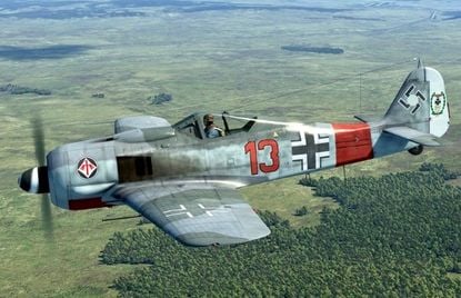
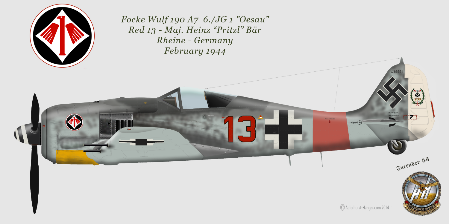
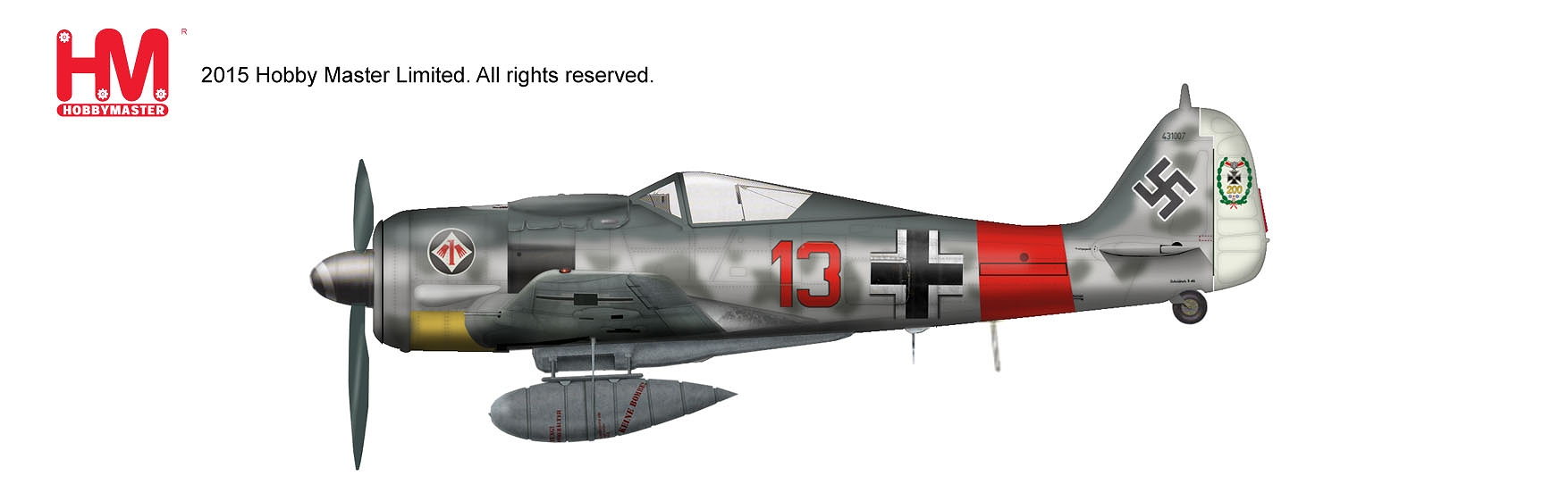
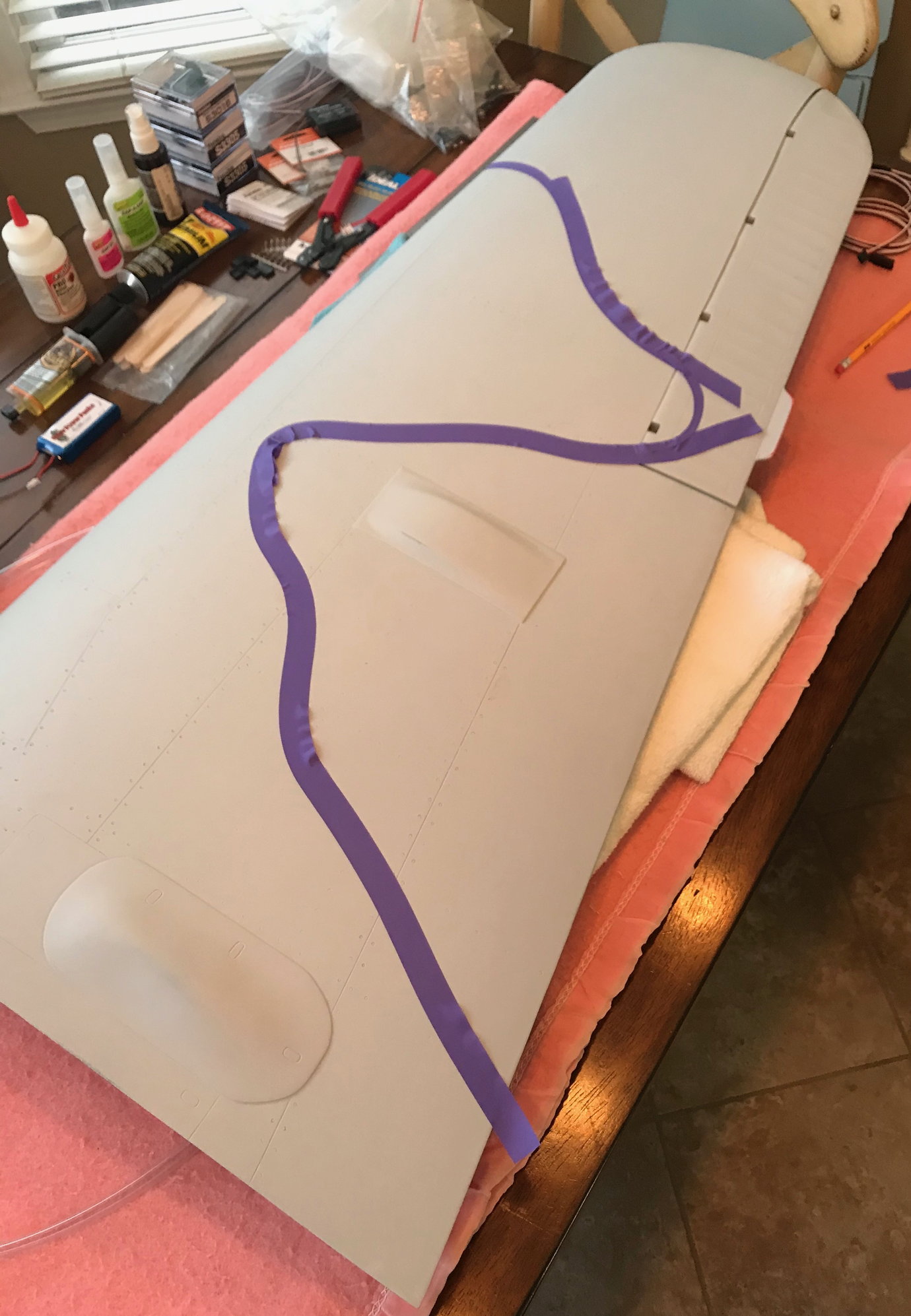
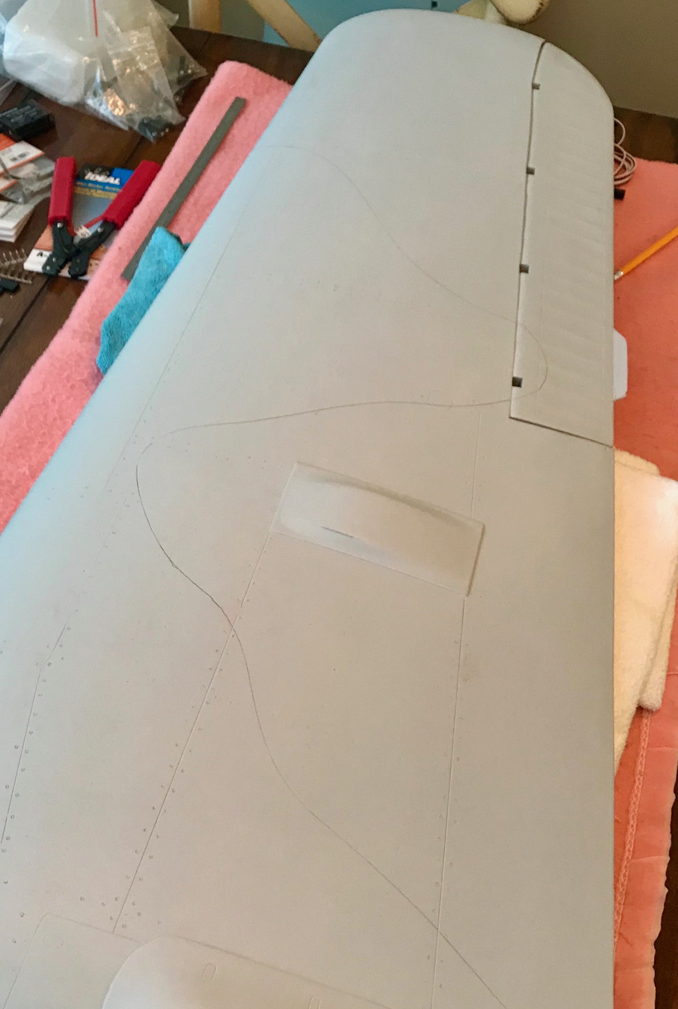
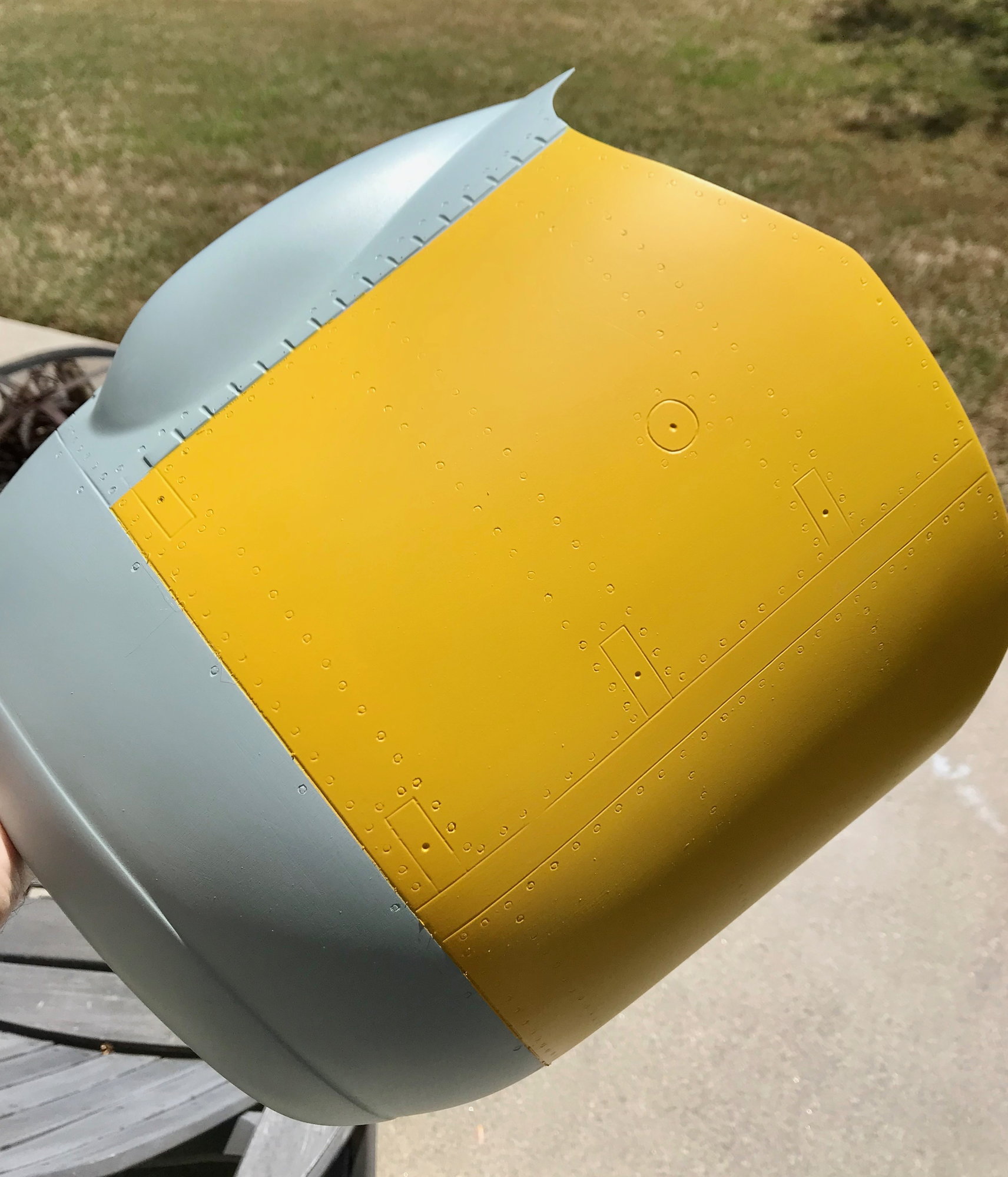
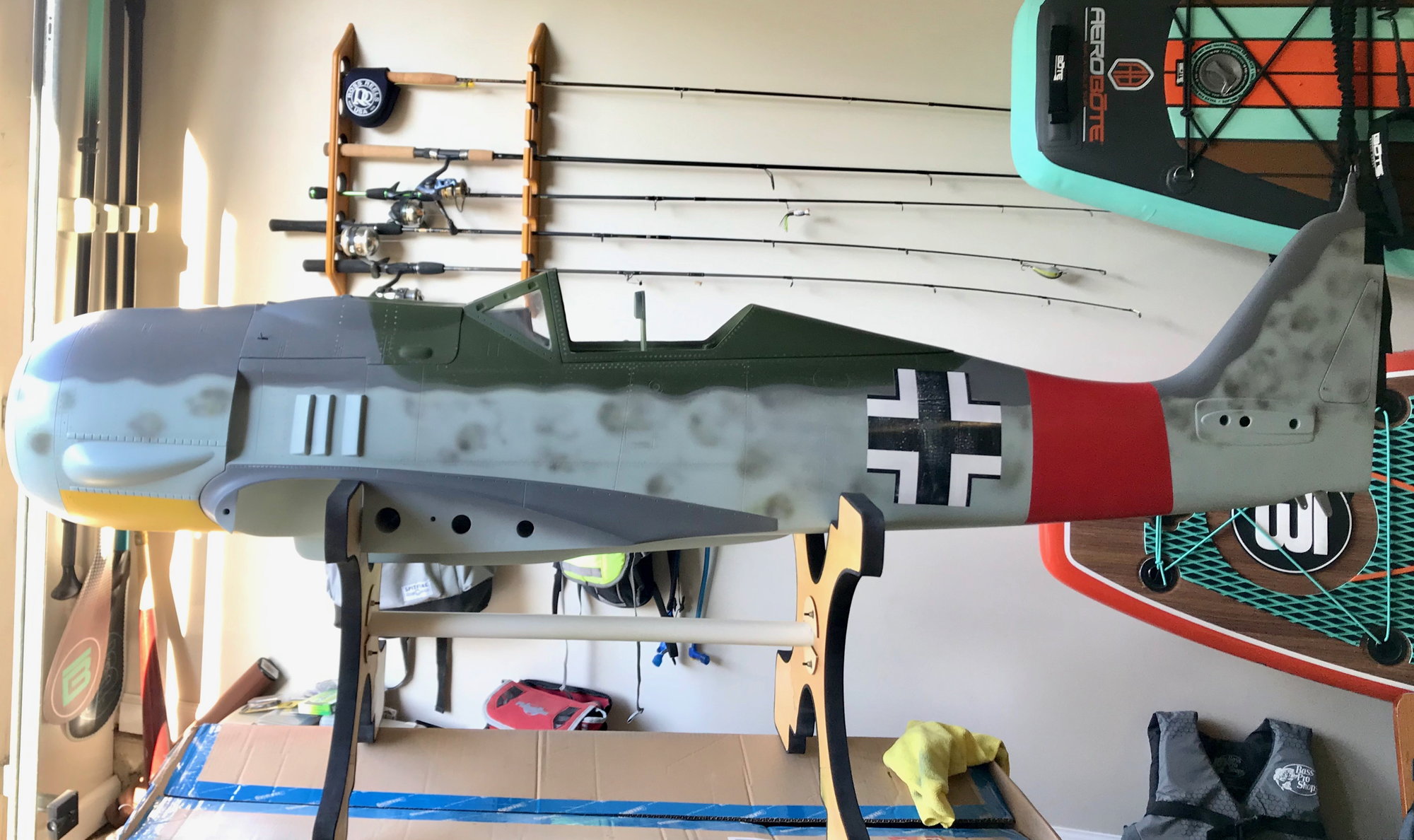
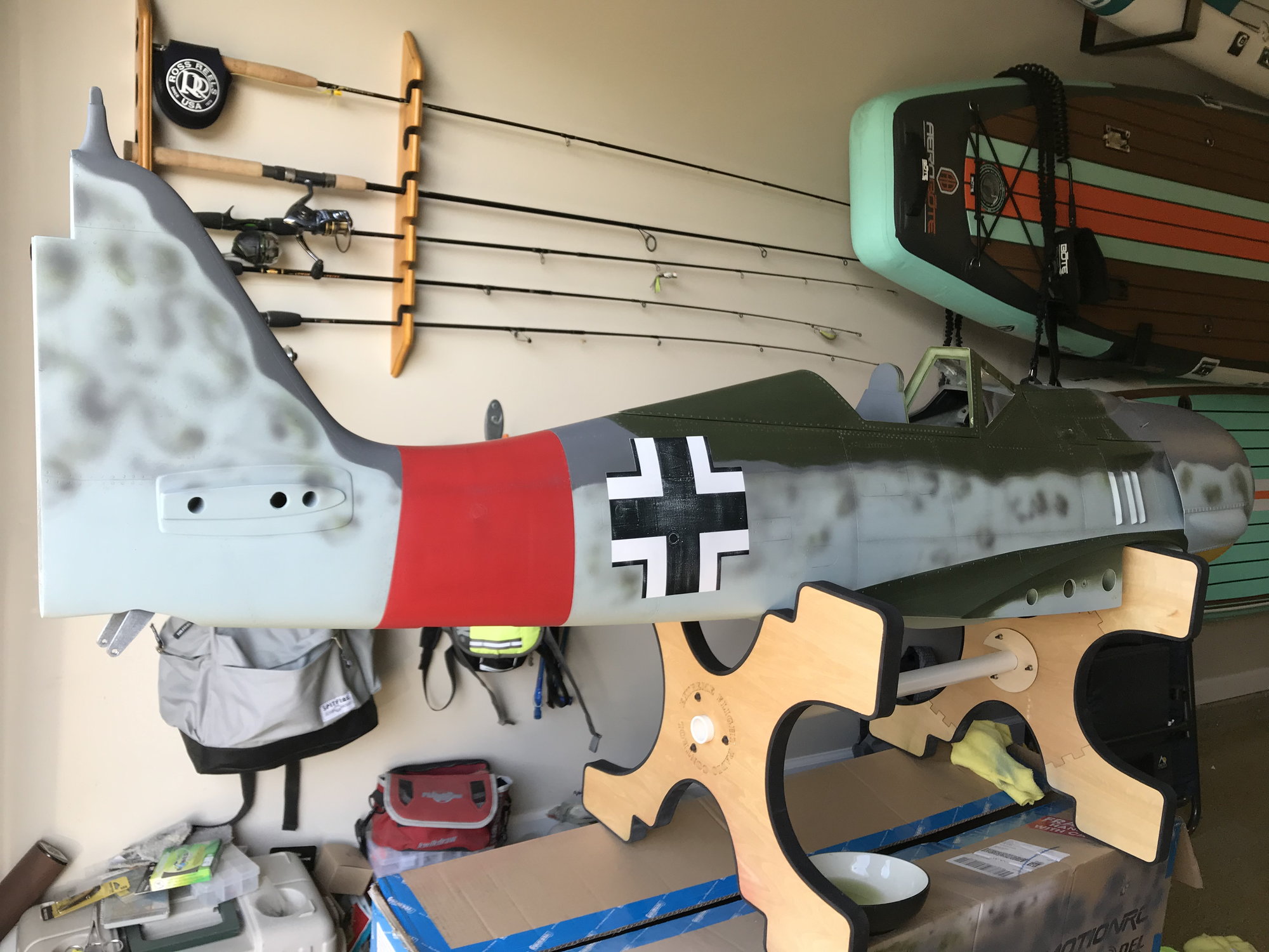
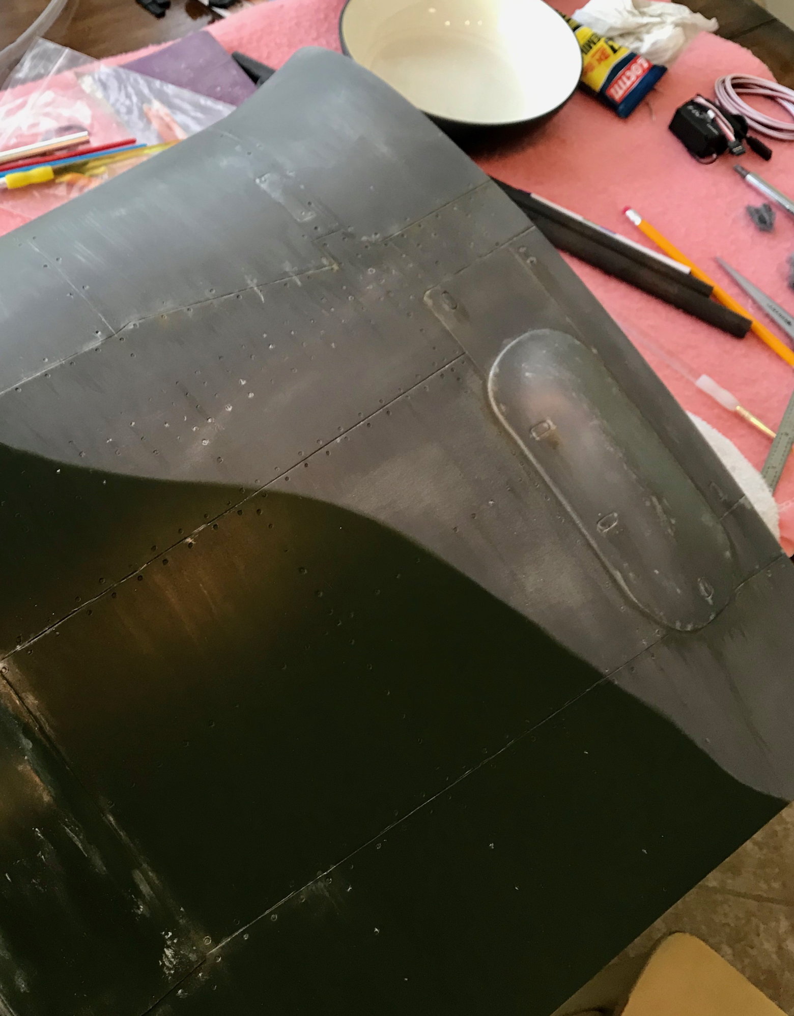
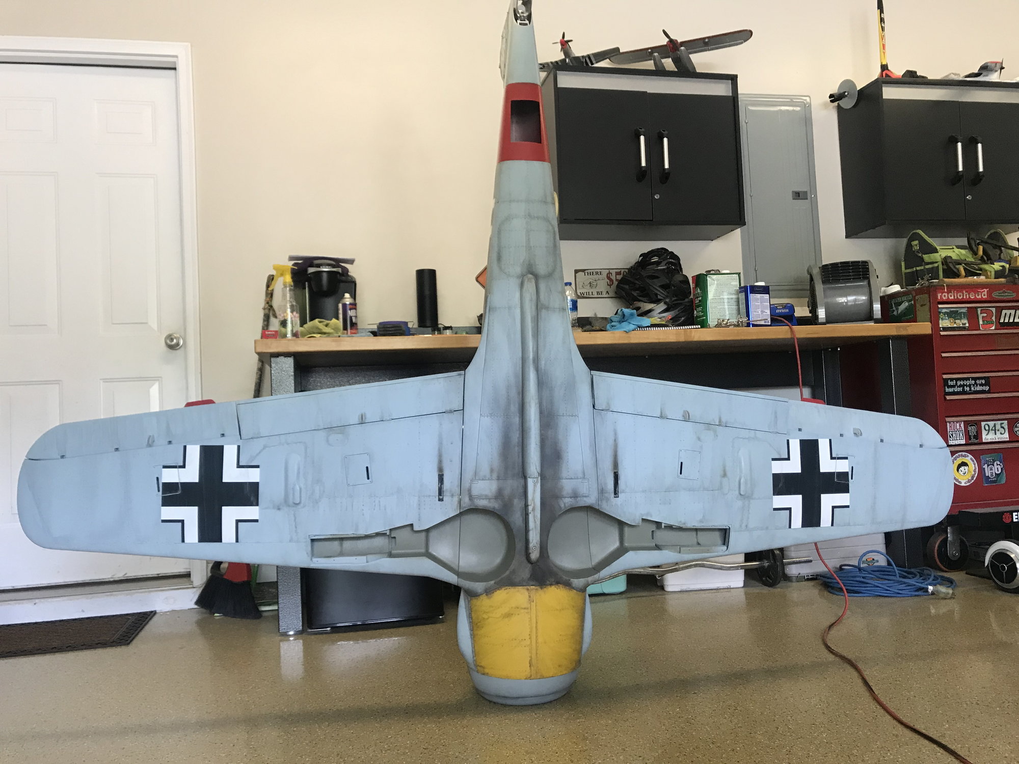
Sooooo, i have been lurking on this site for quite awhile now. i picked up this kit last year and started to get hot on it earlier this year. The first thing i did was look at many - MANY different FW's and decided to stay w the Red 13 scheme. I finally narrowed it down to several pics to use as a reference and then decided to start prepping the aircraft for a new paint job.
Last edited by jraycut; 06-07-2020 at 06:02 AM.
 06-07-2020, 06:15 AM
#862
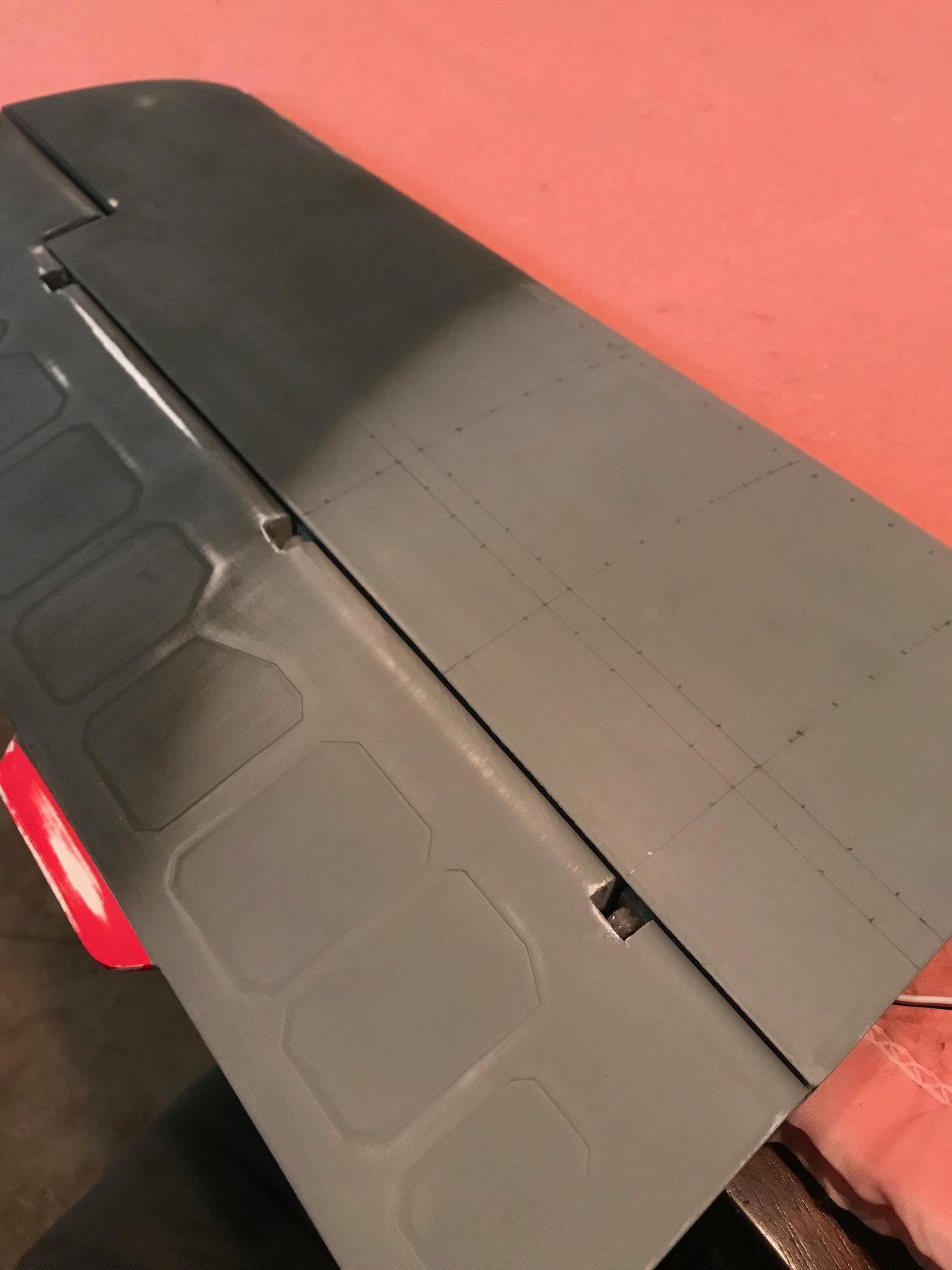
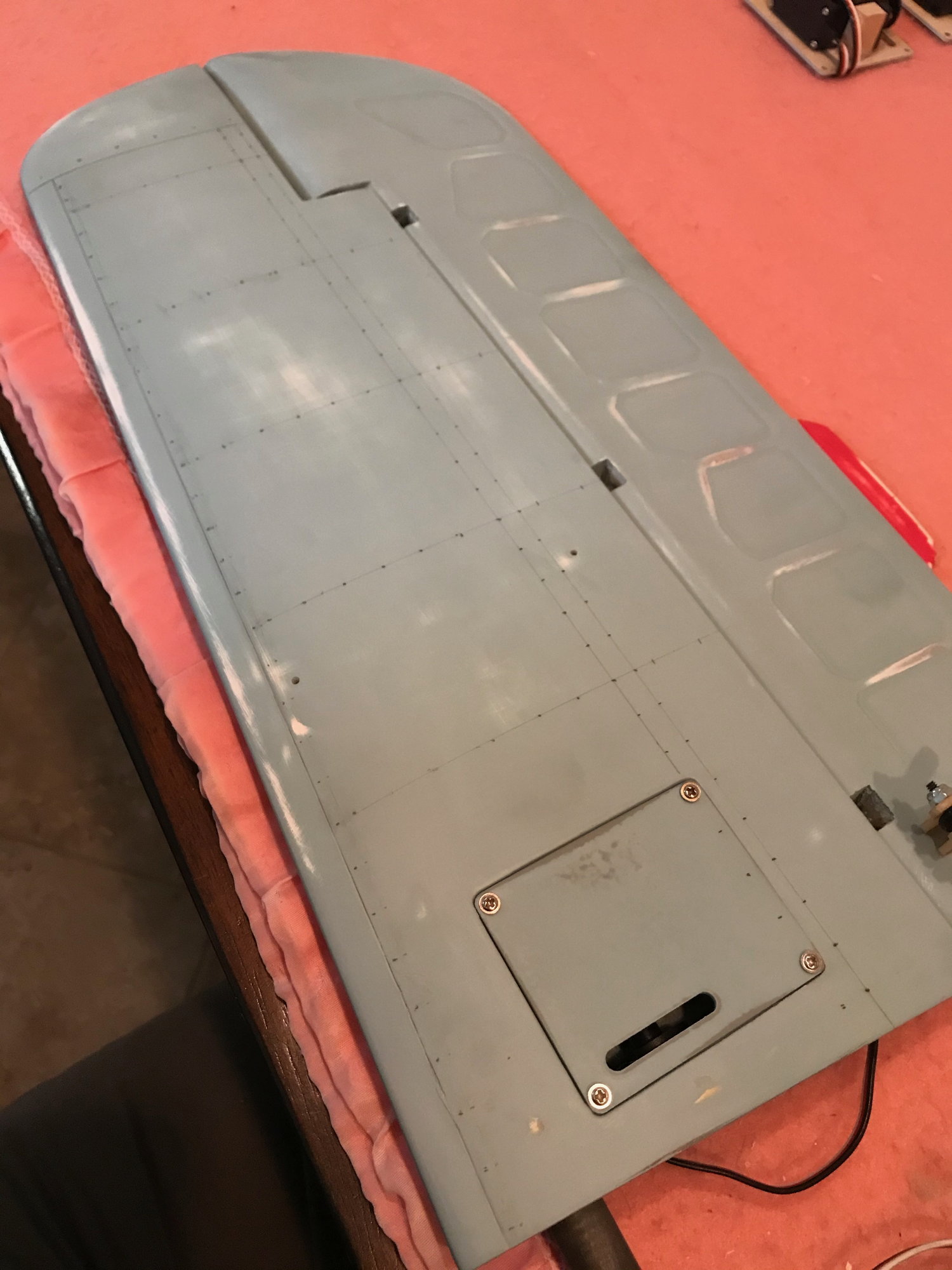
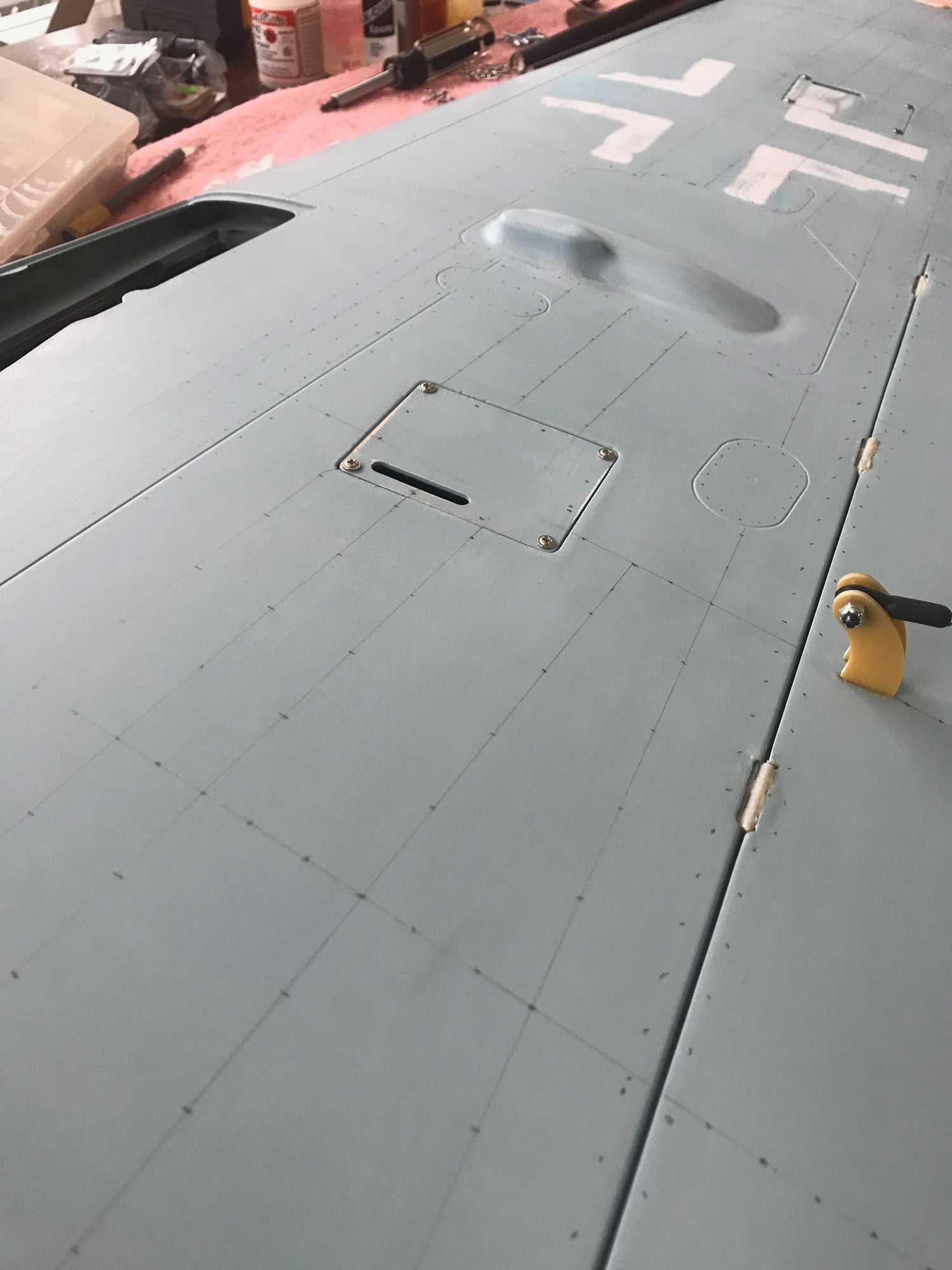
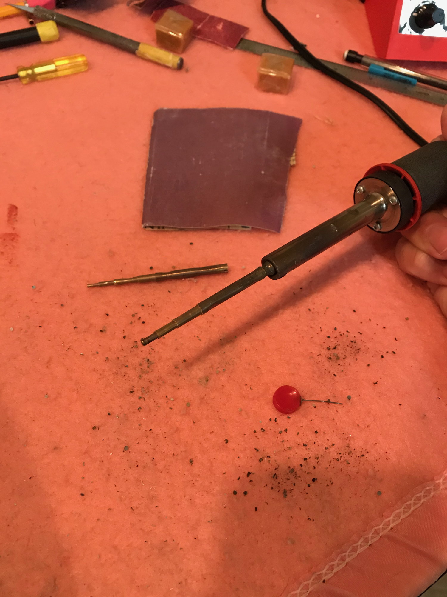
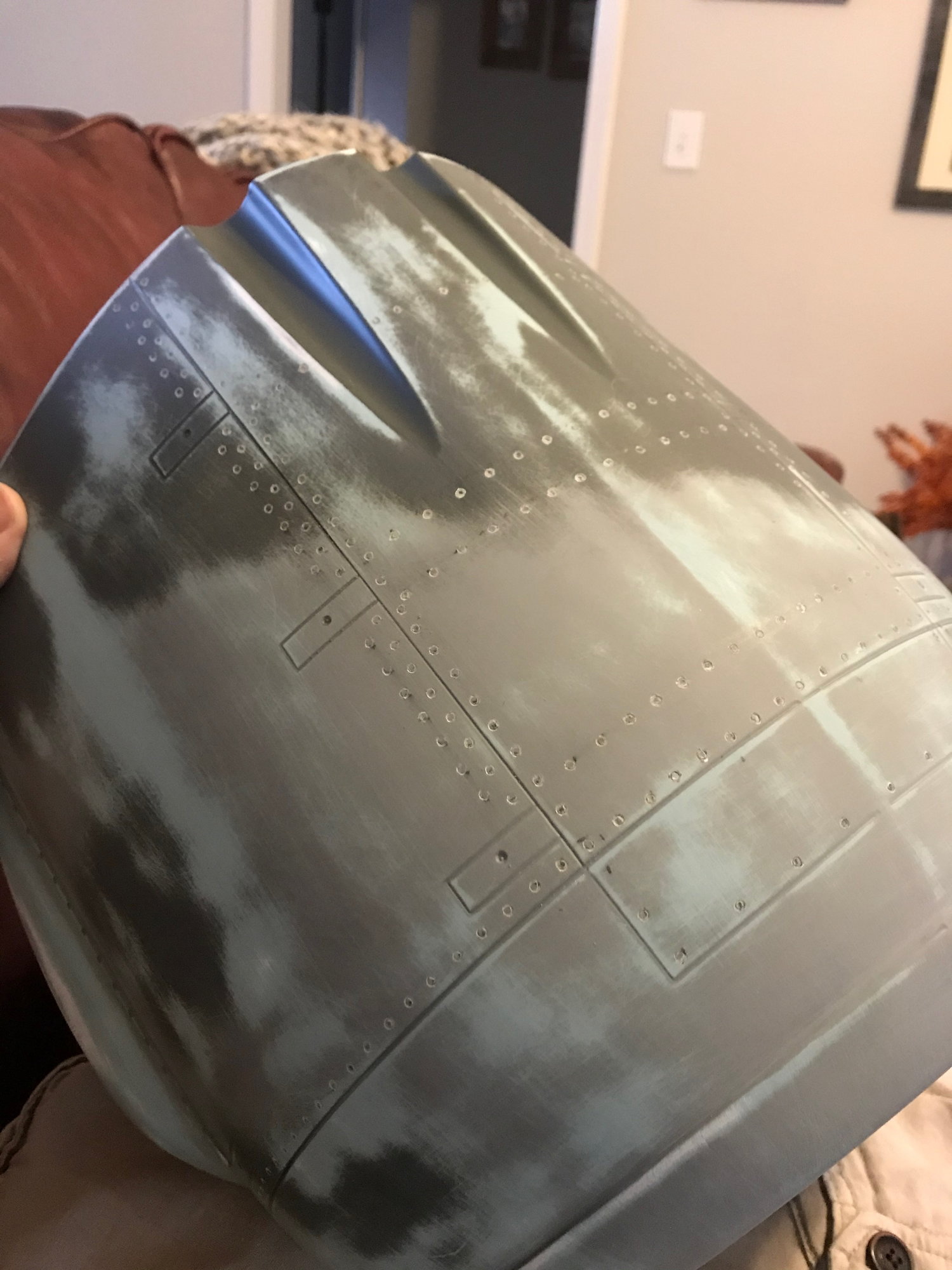
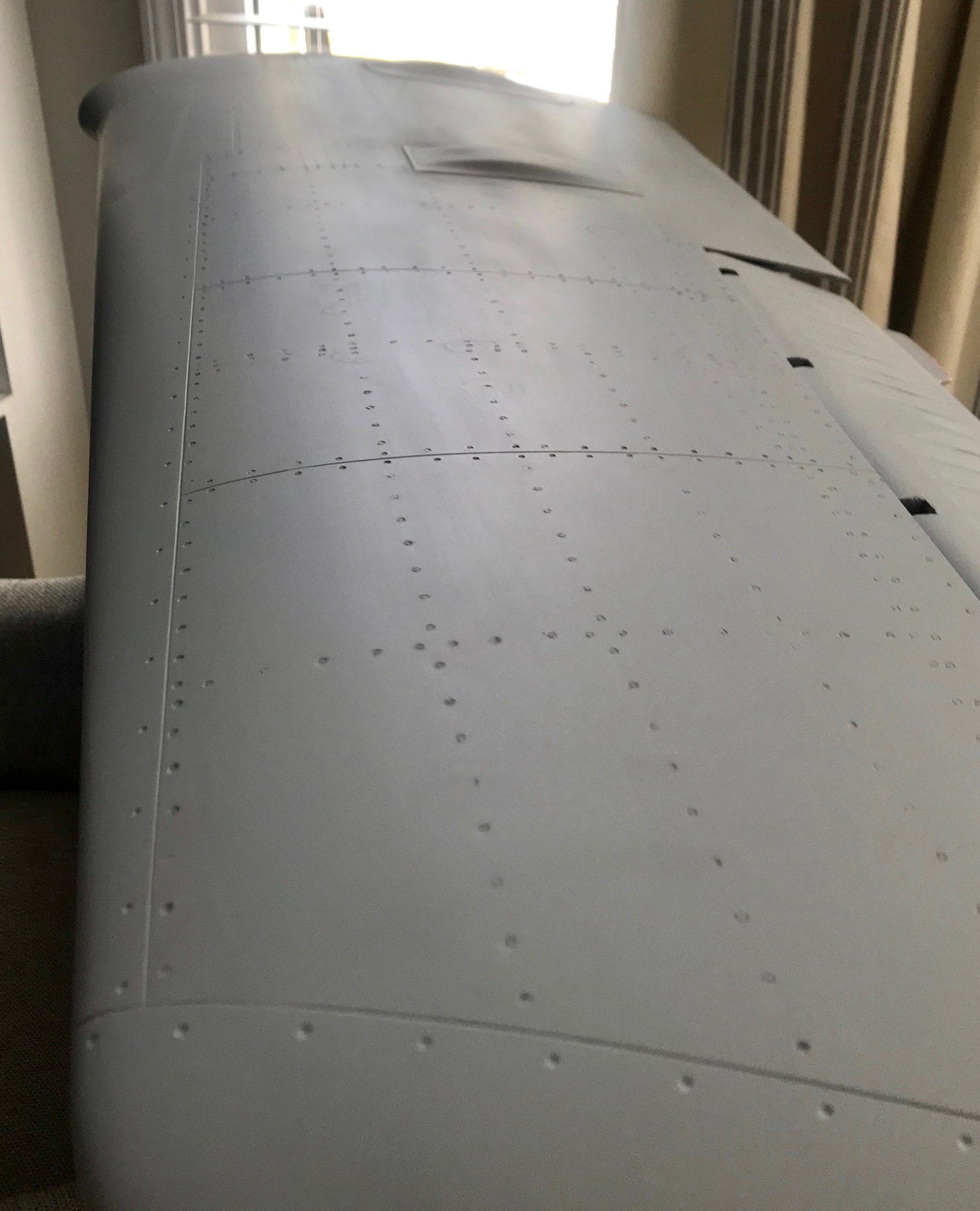
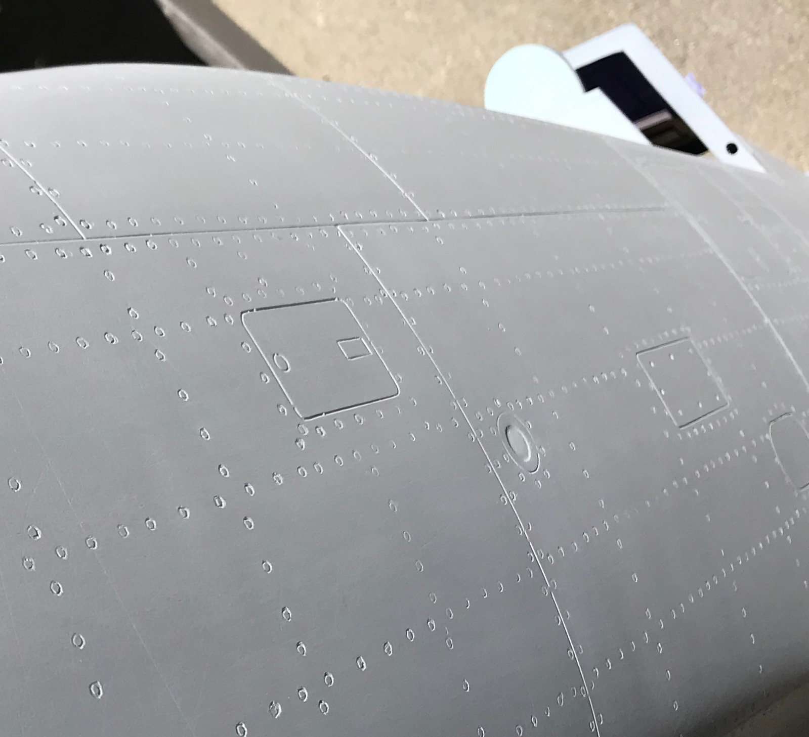
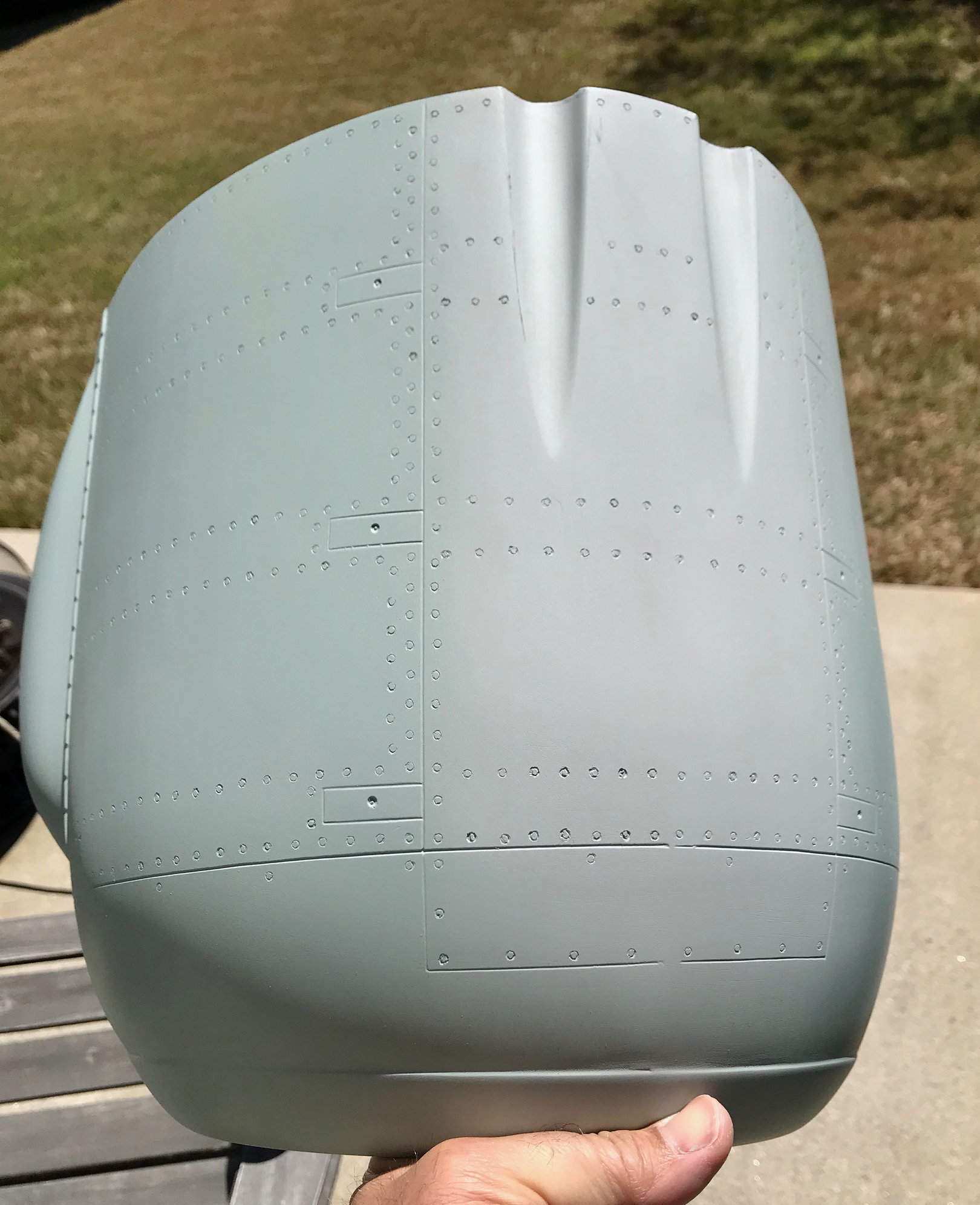
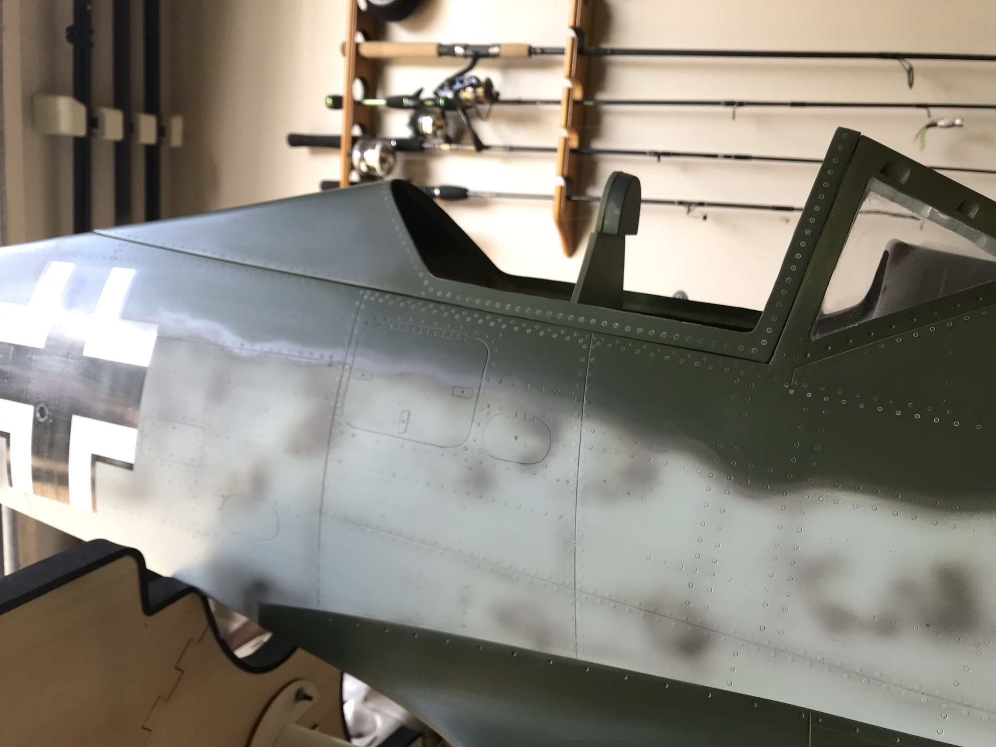
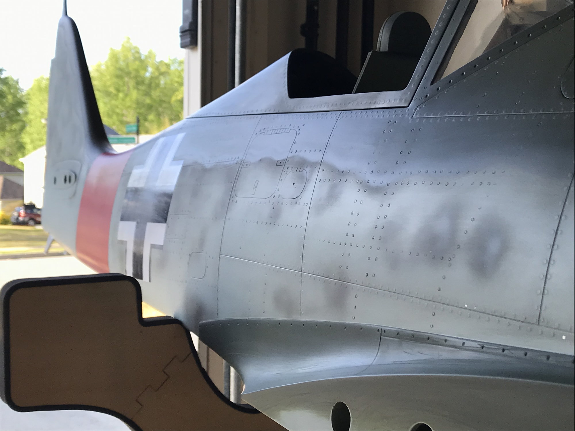
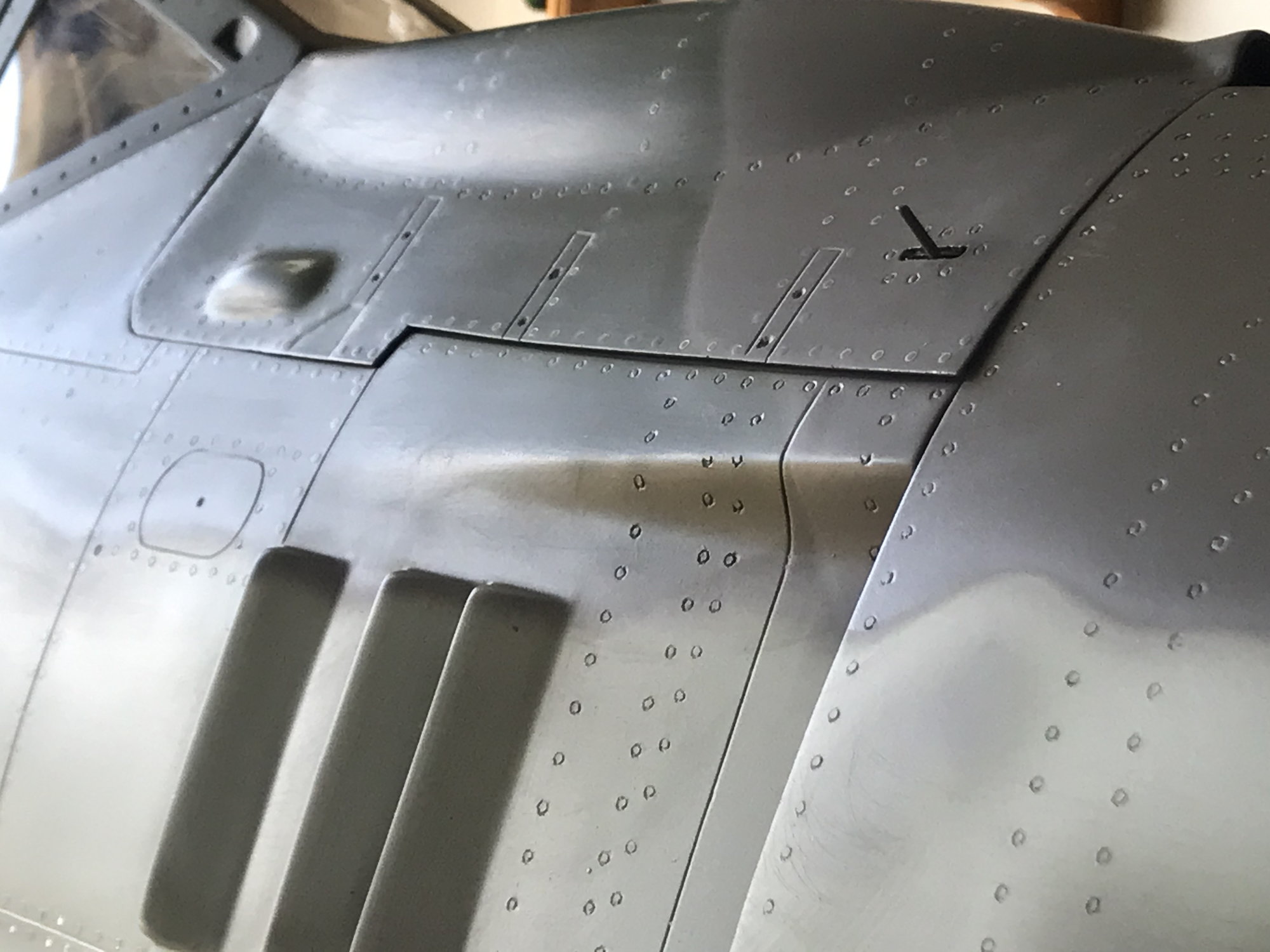
once everything was sanded and cleaned up, I decided to add some rivet detail to enhance the scale looks. First was laying out the detail w a pencil, then I made a tool that slips on the end of a soldering iron made out of brass tubes to get the diameter i am after. i went this route as the majority of the rivets on the FW are flush...but I also decided to use some stick on rivets from Chad W. Veich - Scale Model Design & Construction. He can make these rivets in any size you need, just give him a call w what youre after.
06-07-2020, 06:26 AM
#864
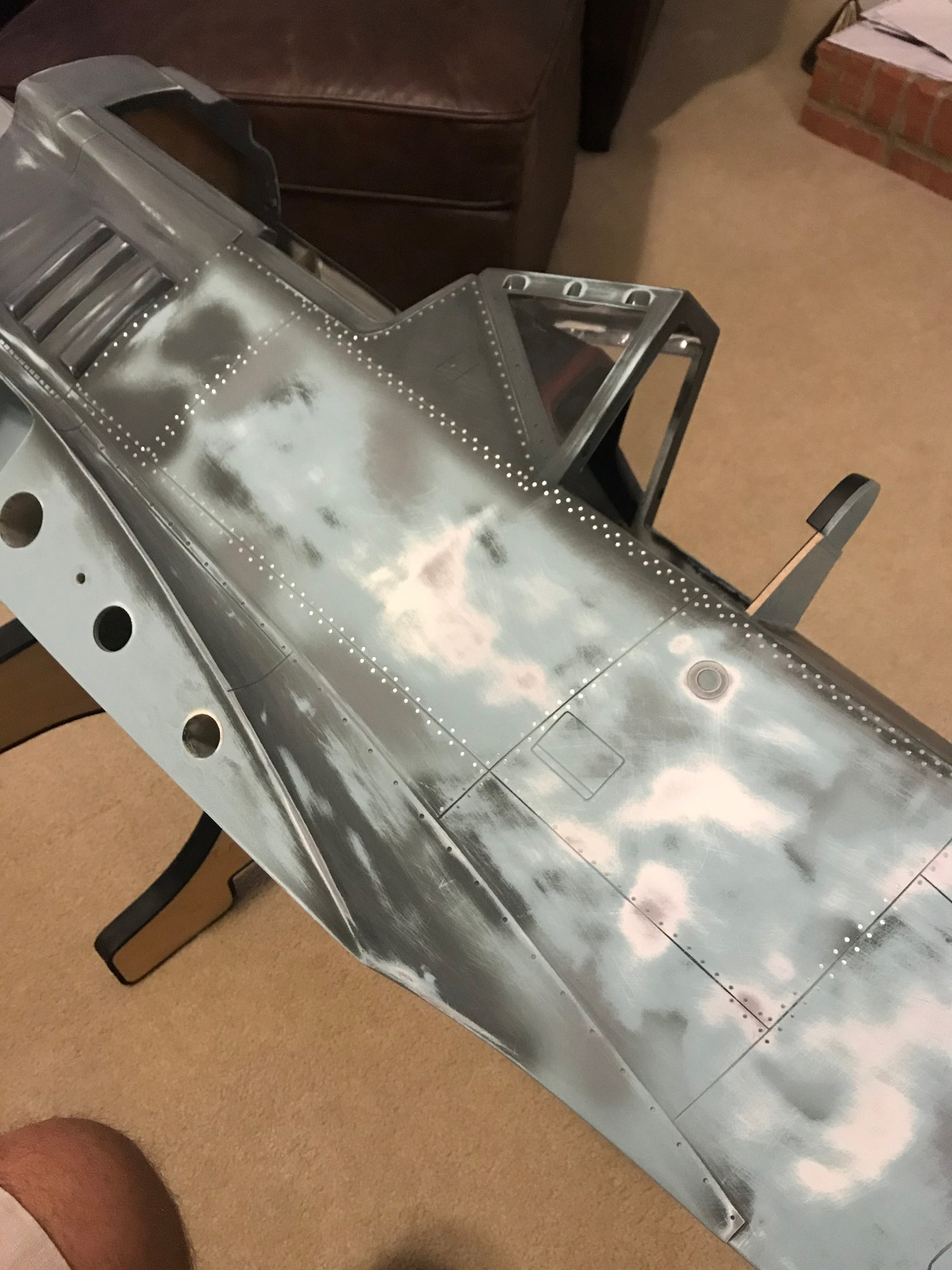
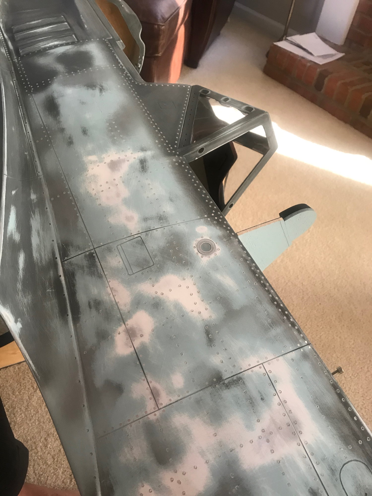
You can see where i used Chad's rivets around the sides of the fuselage and everywhere else i did the rivets one by one w the soldering iron - be patient...as this process takes time - but - went faster than i anticipated. Once i had all the rivets in place, i did another light sanding to make everything nice and smooth (except where used chads rivets as those are raised above the surface.

06-07-2020, 06:30 AM
#865
Thank you! Yes, I do have some guns im going to add. I decided not to apply the armament (I was going to use foil tape (speed tape) like we use on full scale aircraft to simulate the plating. i decided to just add Chads rivets to immolate the look
06-07-2020, 06:37 AM
#866
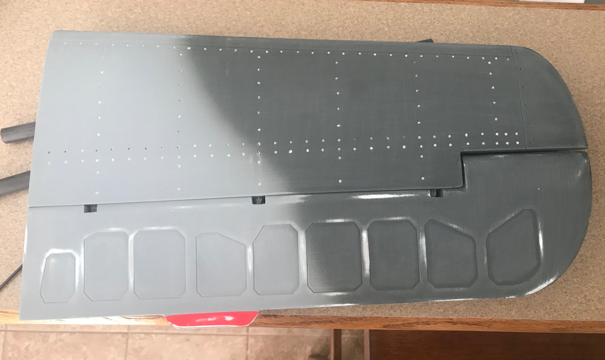
Once all the rivets were added and all pieces were prepped - it was time to shoot the primer on. The last photo is a shot of how the rivet detail came out after a coat of primer.
 06-07-2020, 10:29 AM
#869
06-07-2020, 11:49 AM
#870
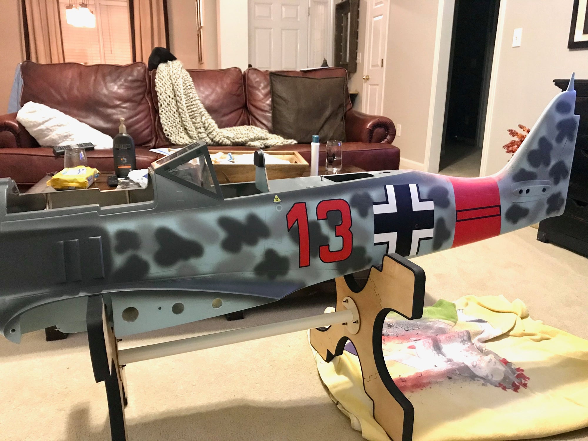
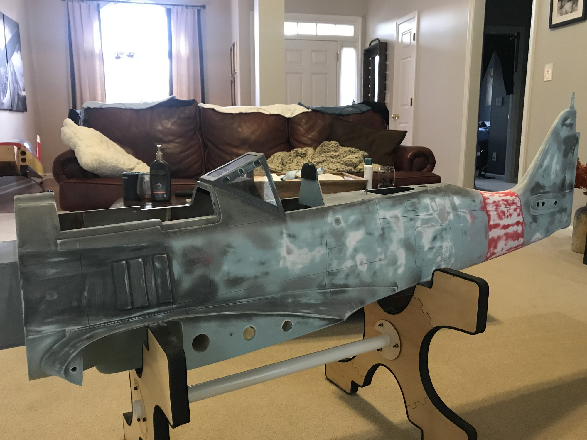
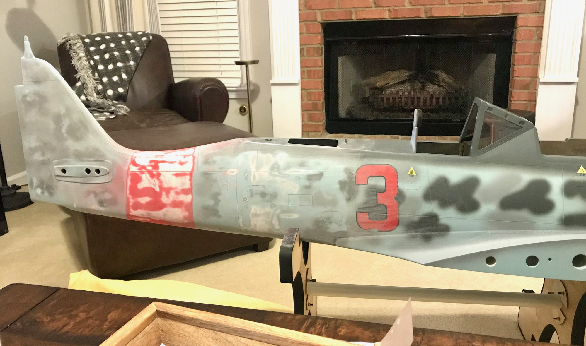
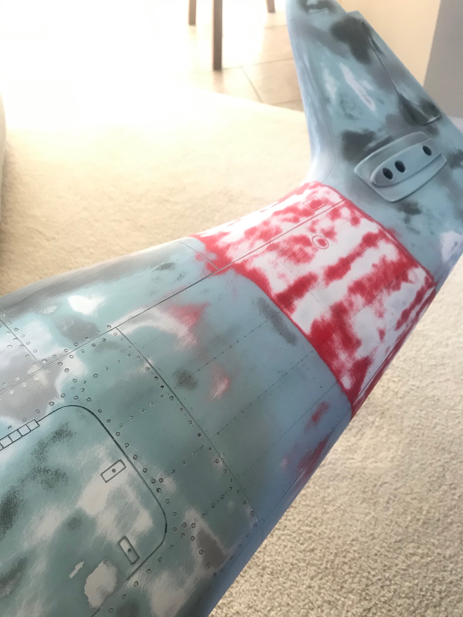
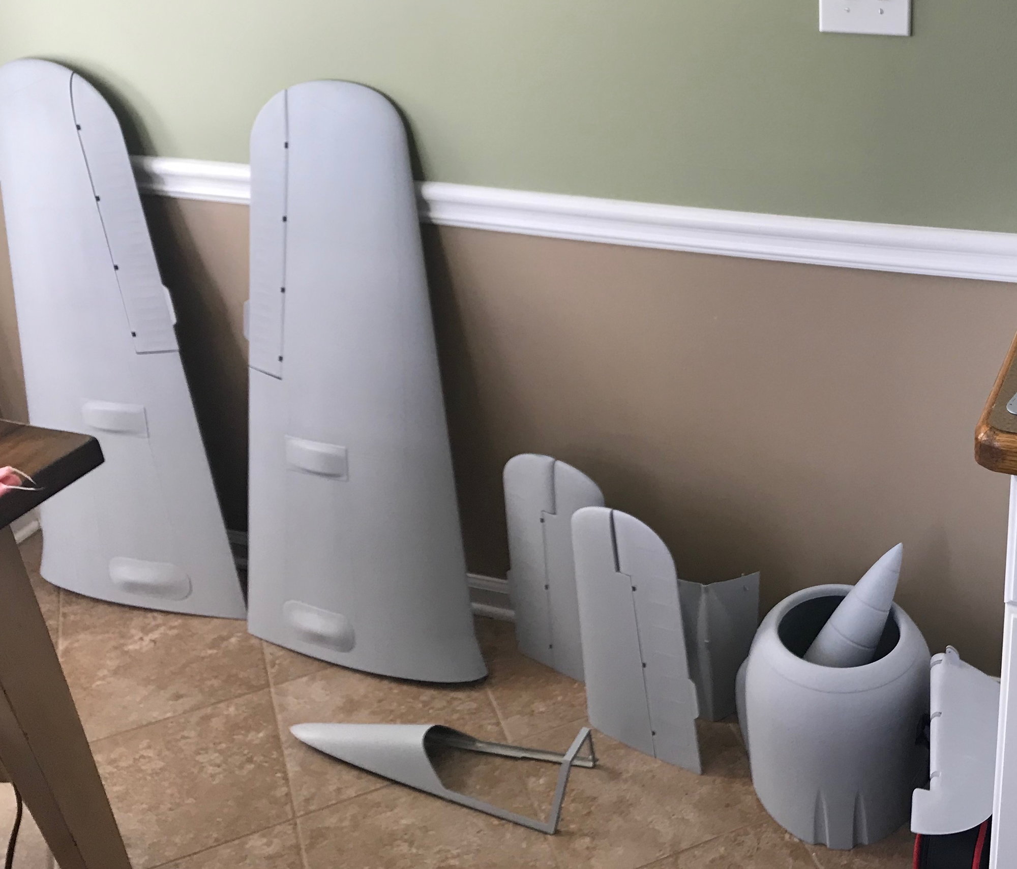
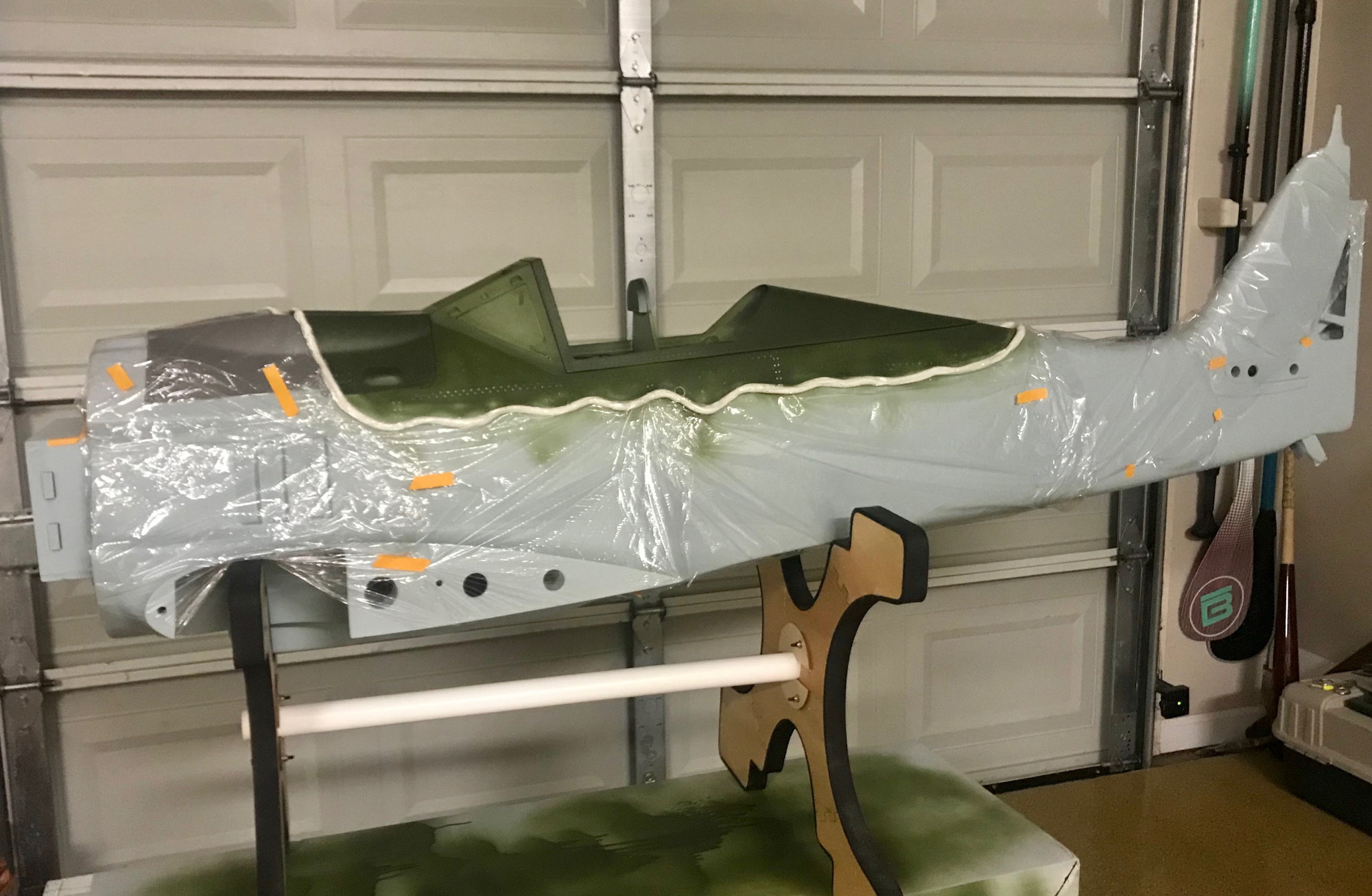
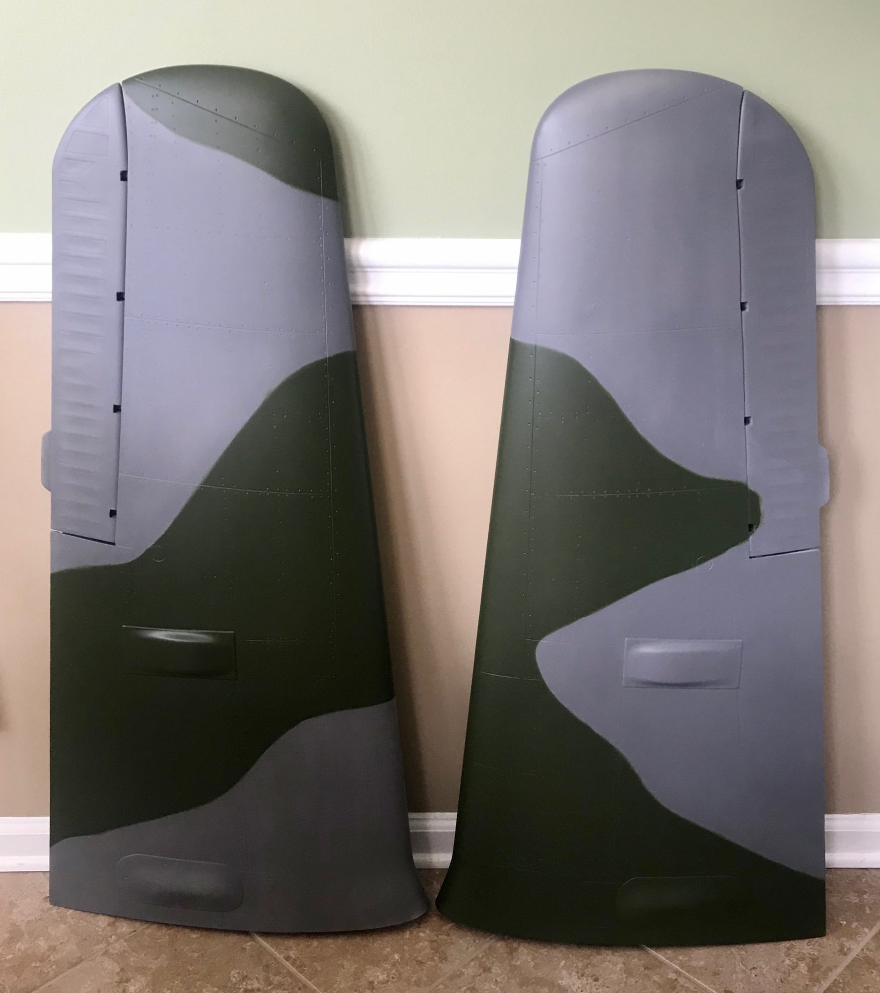
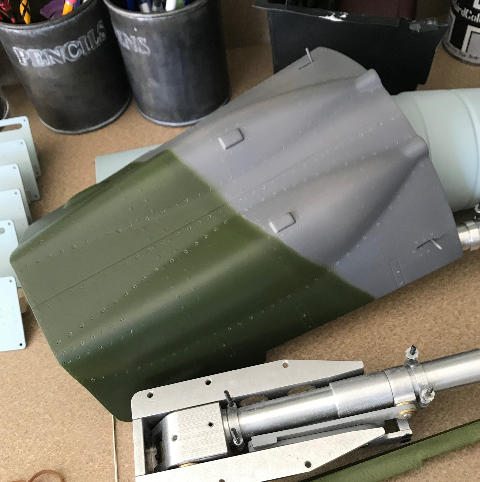
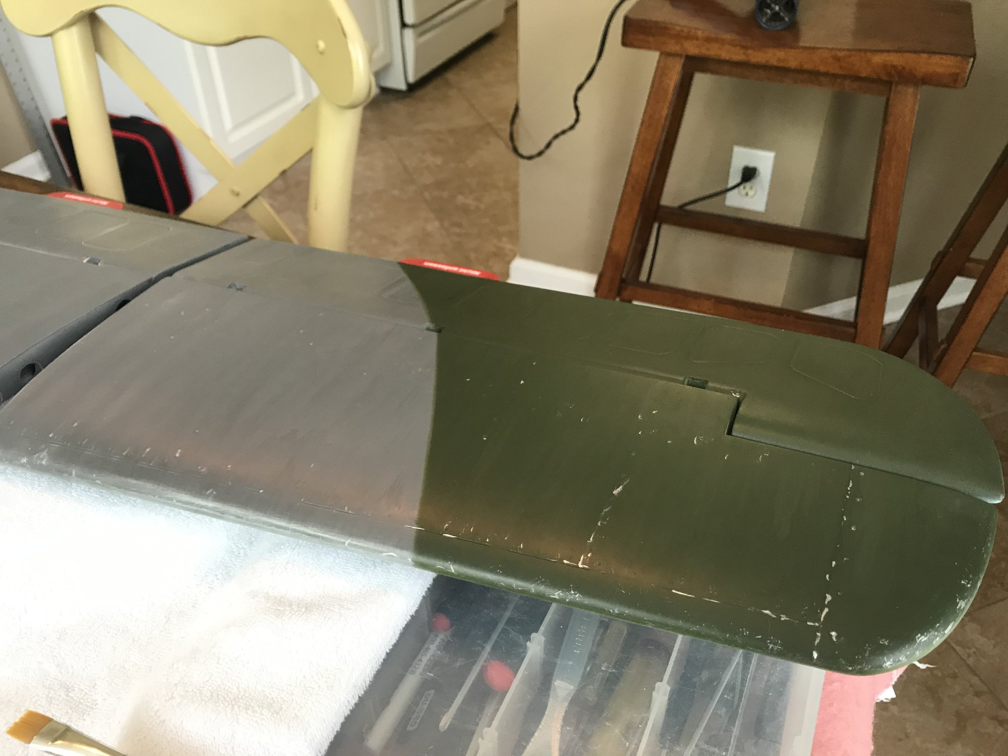
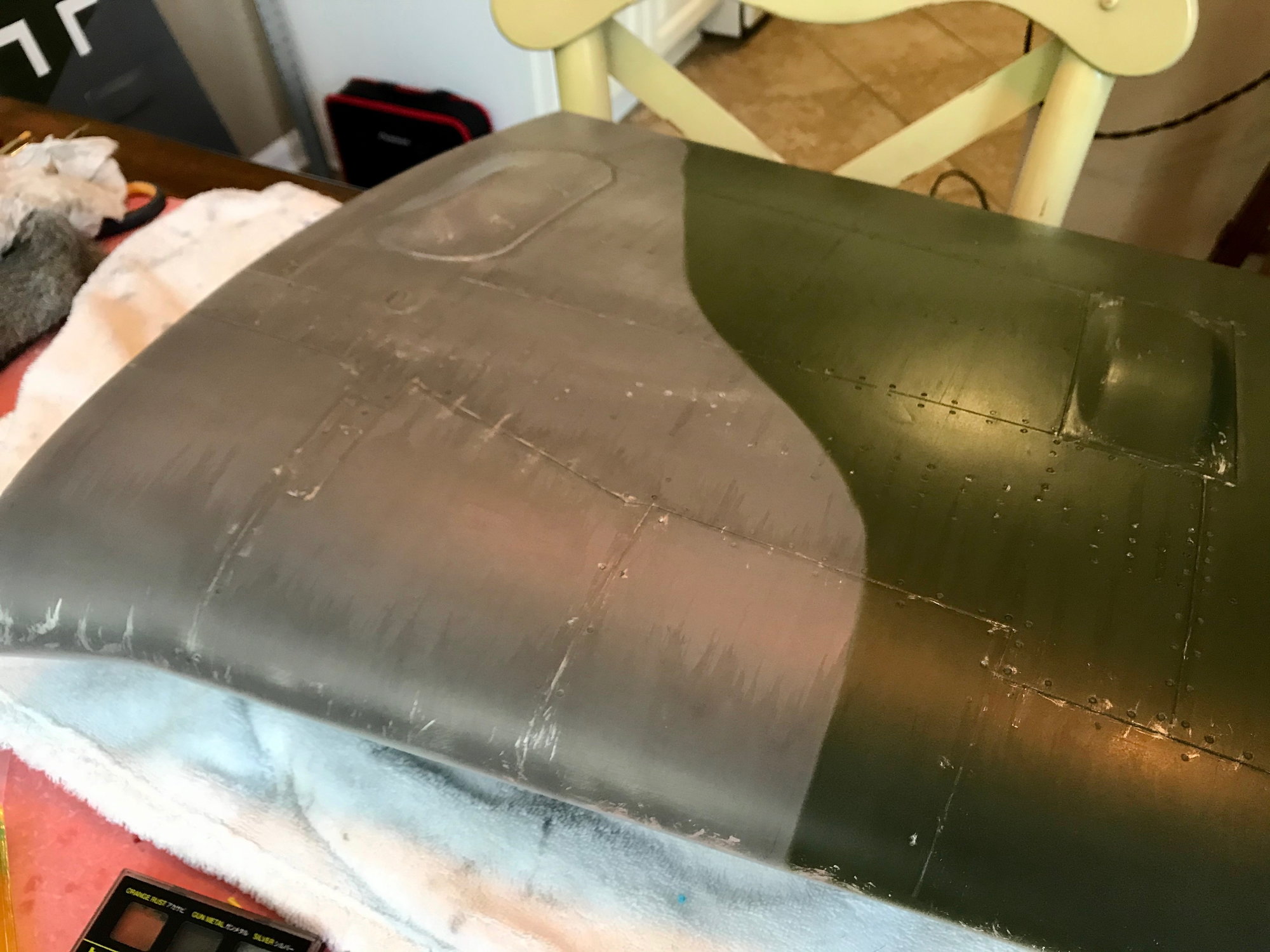
once i got all the primer on and sanded smooth, it was time to commit to the scheme i had in mind.one thing to mention, I knew it was going to be very difficult to duplicate an existing scheme out there, so w that in mind, i gave it my best shot, By no means am i an expert; actually I'm a novice and this is my first warbird paint job attempt - besides one experience in 2018 weathering/detailing a Top Flite FW190, that i ended up selling before fully completing it. I did a lot of research w methods, paints, etc - so this was a learning experience for me and im looking forward to another project =)
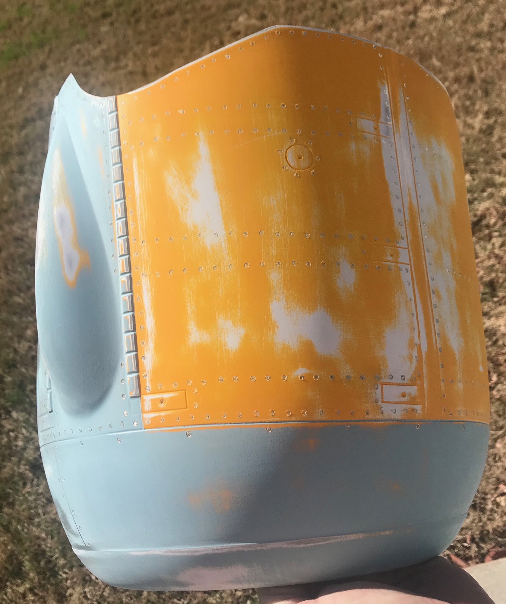
First, was to come up w how to do the camouflage - i came across a method i felt most comfortable w and that was by using an item that is most comparable to that of silly buddy called Blue Stick which i couldn't find locally and ended up using something very similar from Michaels https://www.michaels.com/adh�sif-mas.../10371362.html. I bought several packs and rolled them together to get the outline i was looking for, used Saran Wrap to mask off areas i didn't want painted and the rest is history.
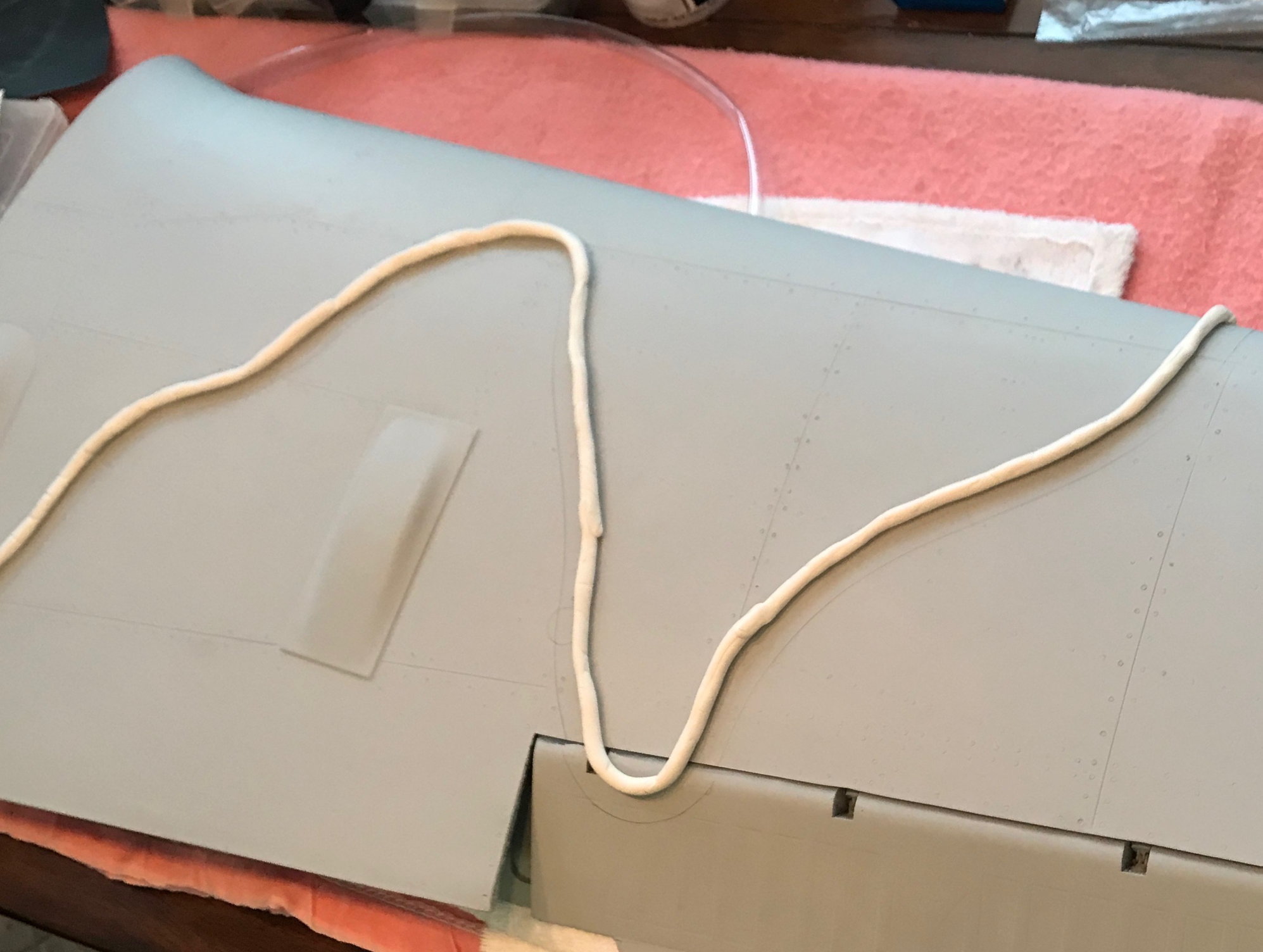
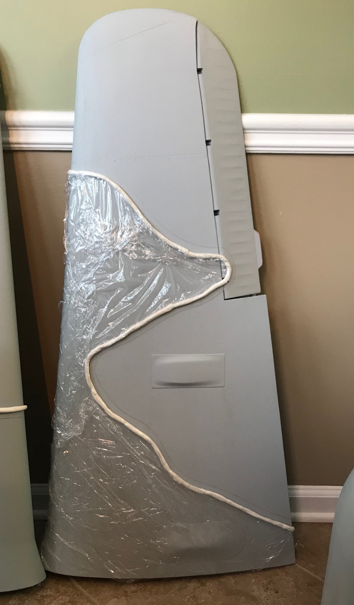
First, was to come up w how to do the camouflage - i came across a method i felt most comfortable w and that was by using an item that is most comparable to that of silly buddy called Blue Stick which i couldn't find locally and ended up using something very similar from Michaels https://www.michaels.com/adh�sif-mas.../10371362.html. I bought several packs and rolled them together to get the outline i was looking for, used Saran Wrap to mask off areas i didn't want painted and the rest is history.
06-07-2020, 12:02 PM
#871
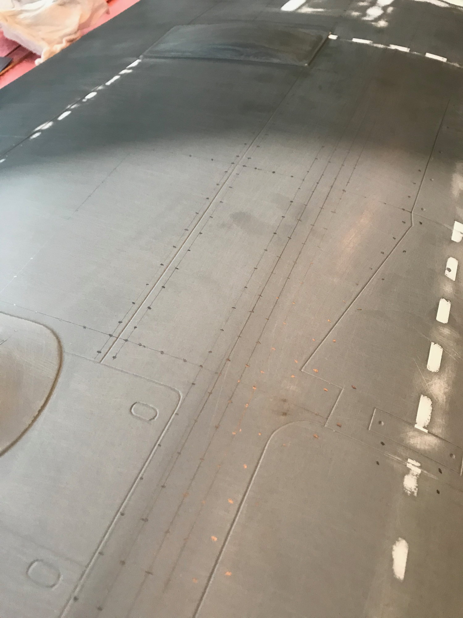
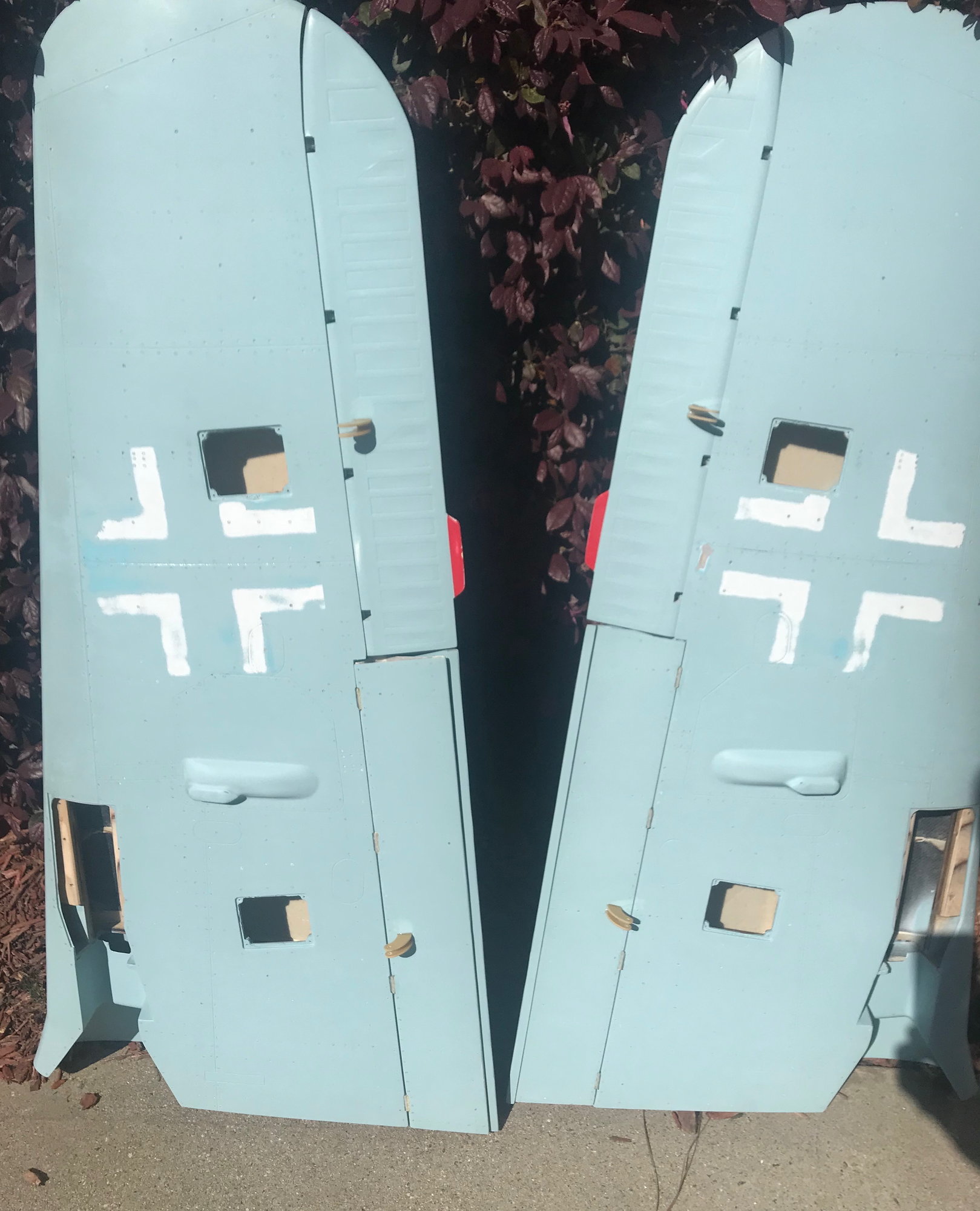
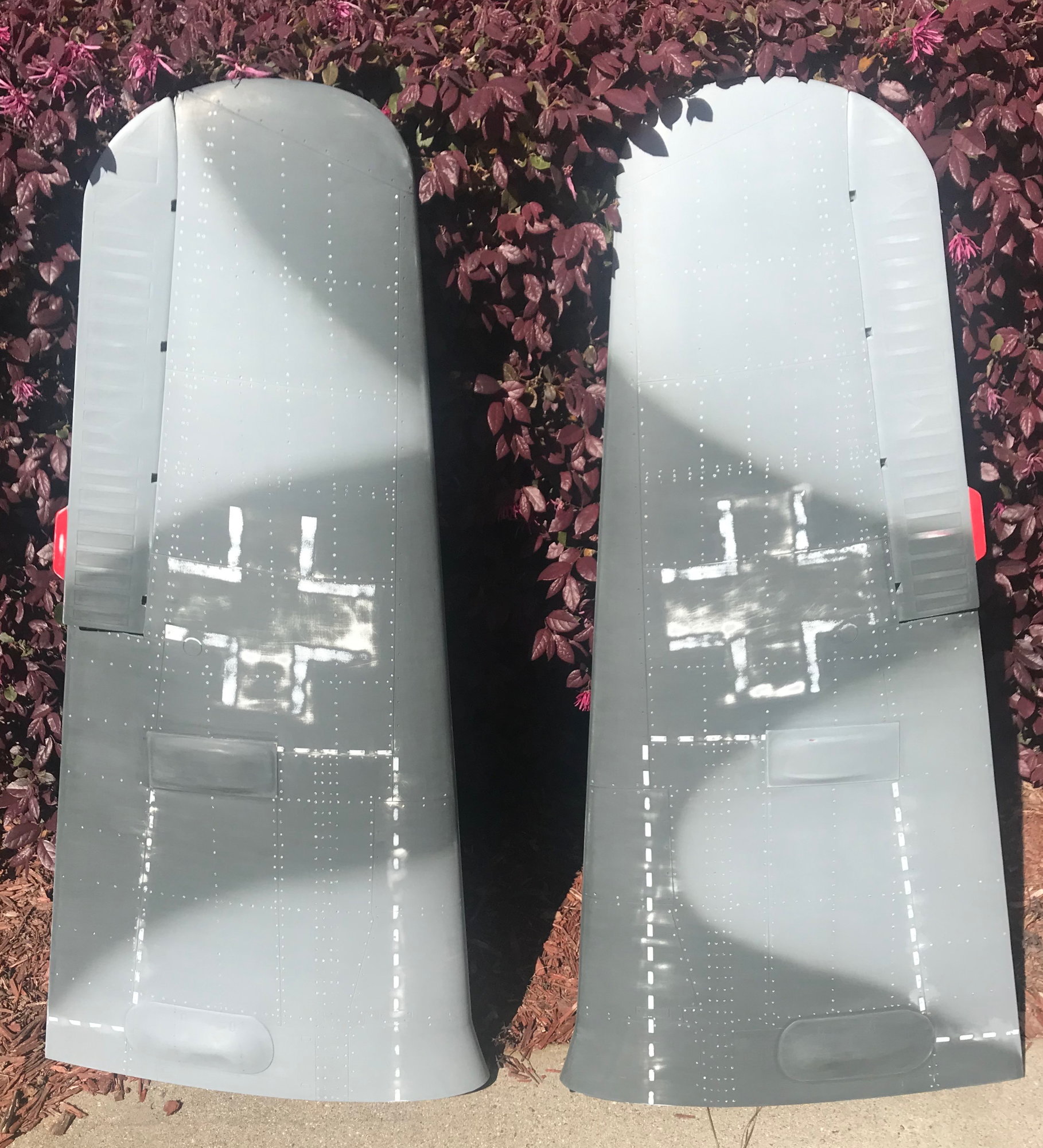
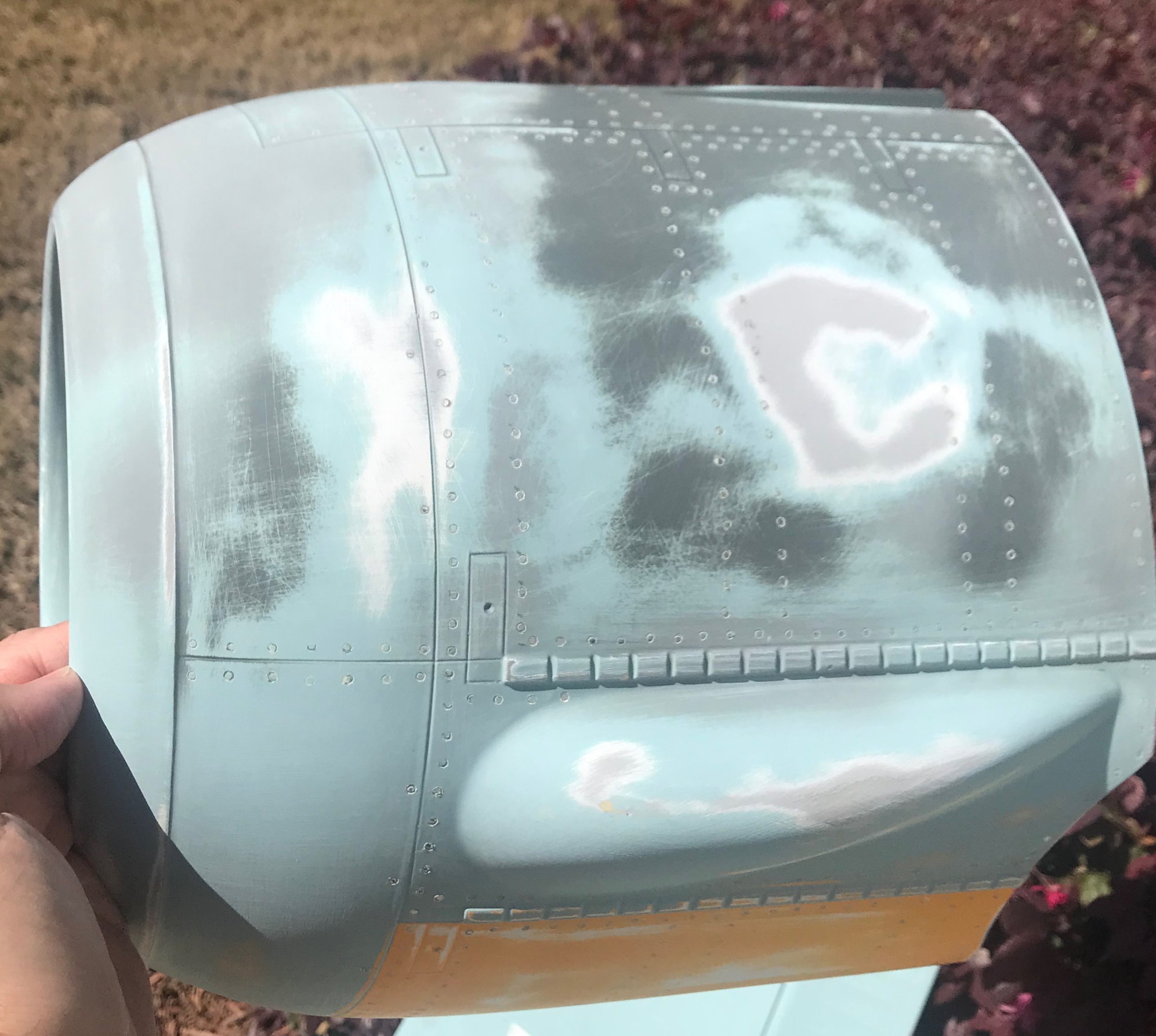
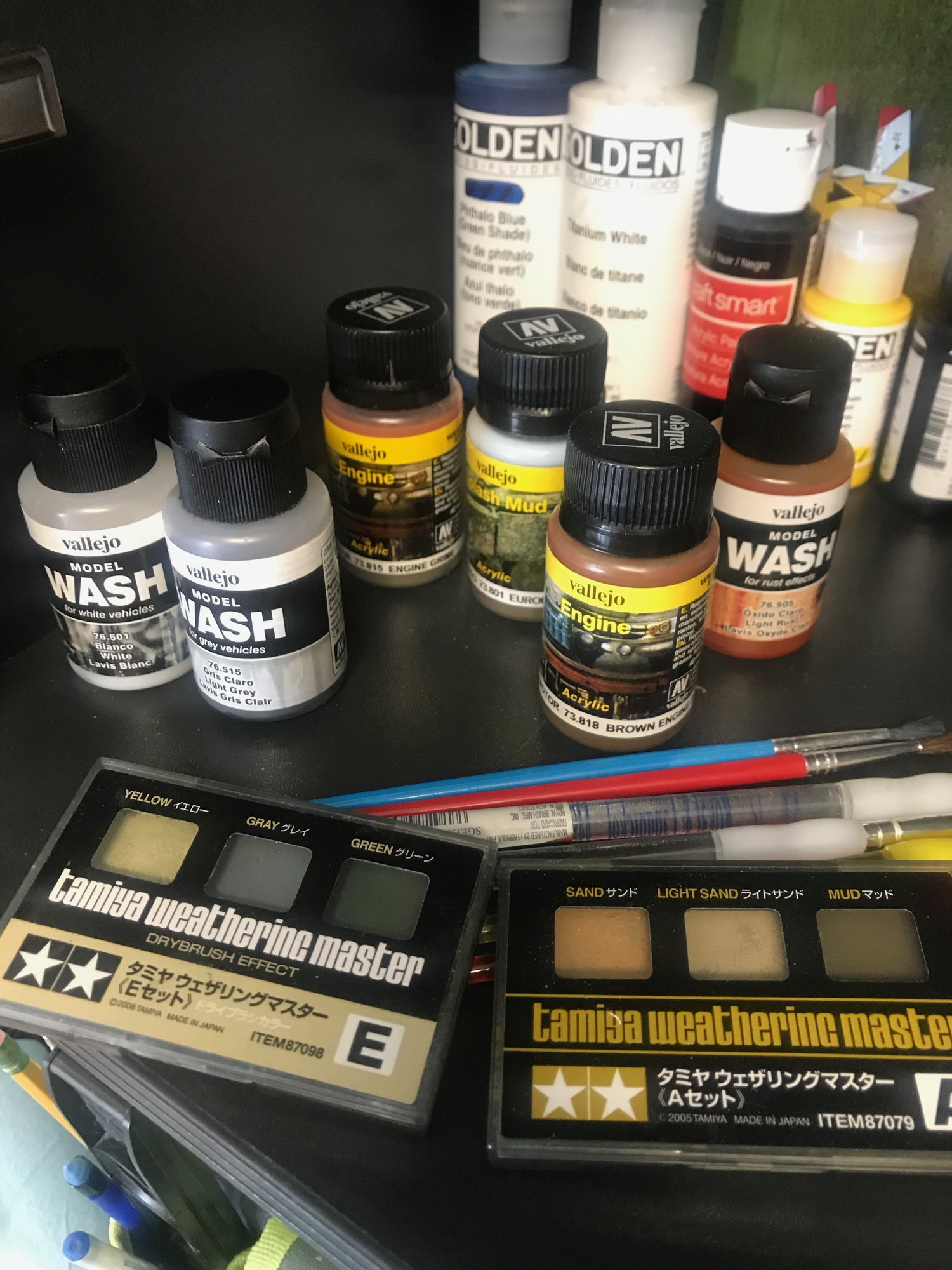
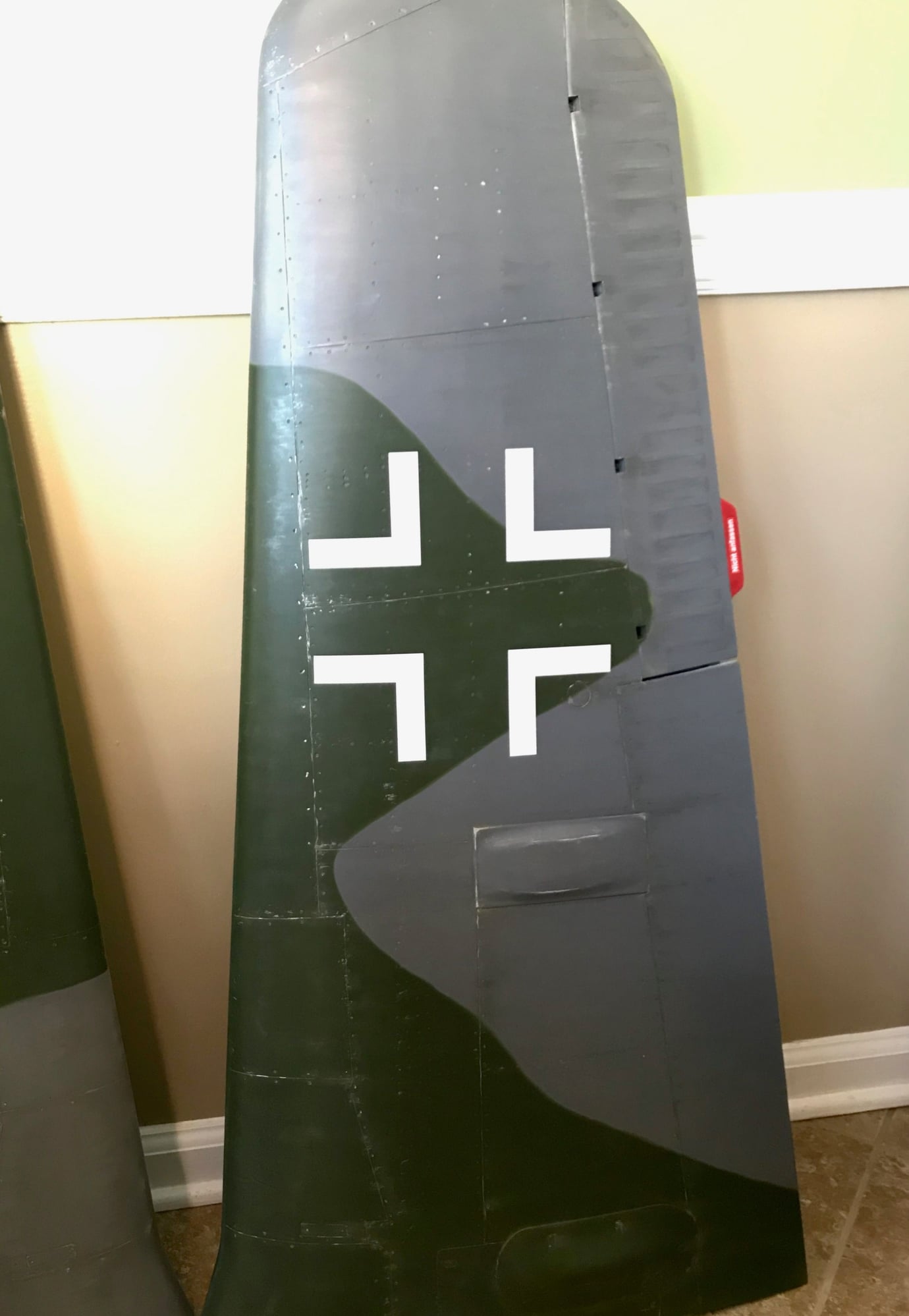
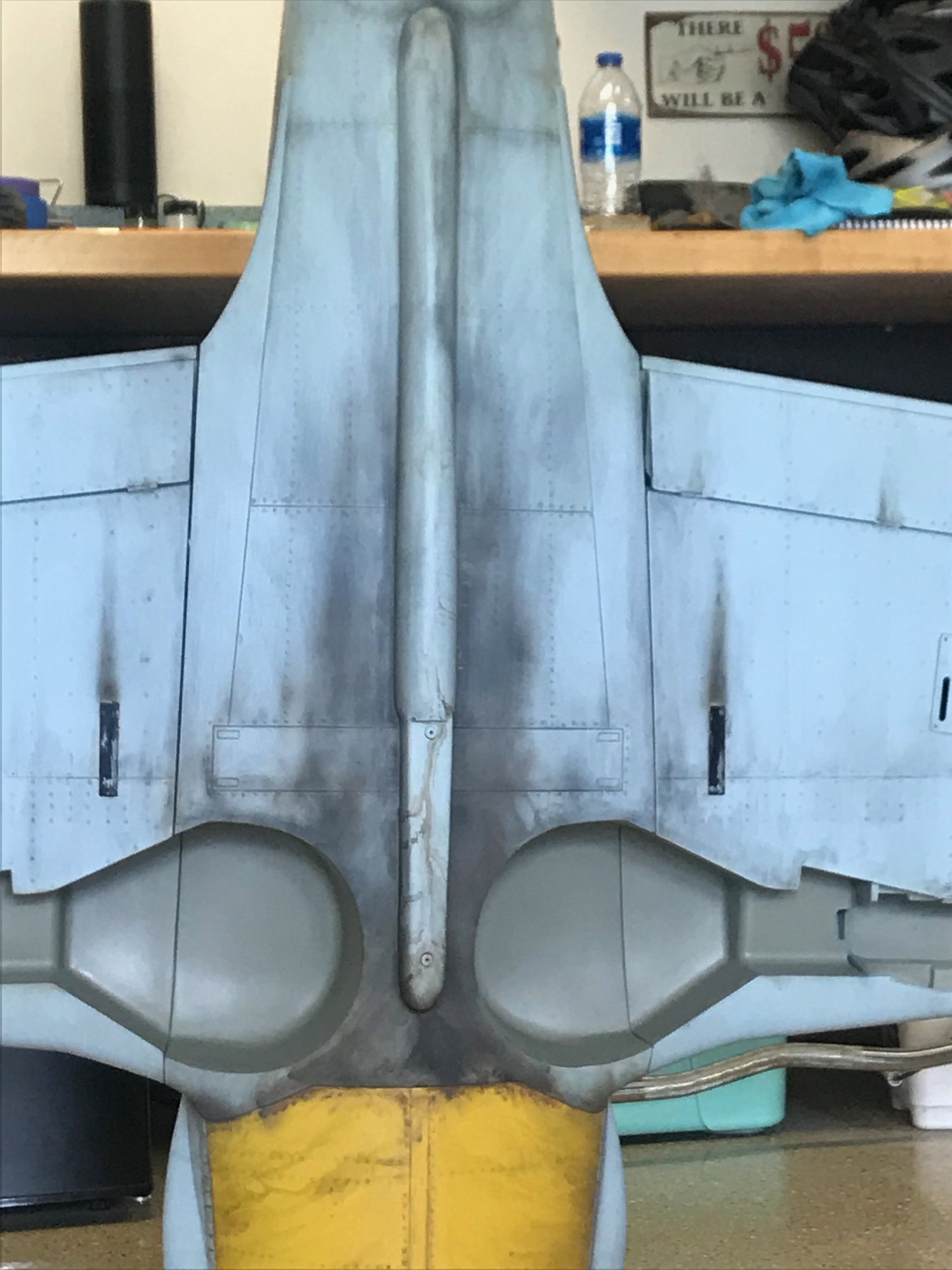
Once i got the primary colors on, it was then time to start weathering the plane. i wrestled w doing weathering or not, but i knew at the end of it all - i wouldn't be satisfied unless i did. I used a variety of items from dust, testers model painters, to washes, etc.
Last edited by jraycut; 06-07-2020 at 12:49 PM.
06-07-2020, 12:42 PM
#872
I had ordered Red 13 graphic set from Callie Graphics https://callie-graphics.com/collecti.../fw-190-red-13. One thing to note is that i had to reorder a couple of the decals that arrived as they were too small. If you do go this route, be sure to measure the items first and let her know what you need resized as the decal set she has (as shown on her site) is what you will receive. I came up w the sizes I needed by going off scale views of the real aircraft. Once I was happy w all the painting, airbrushing, and decals applied, the actual weathering began.
06-07-2020, 01:01 PM
#873
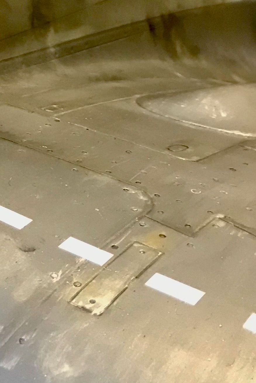
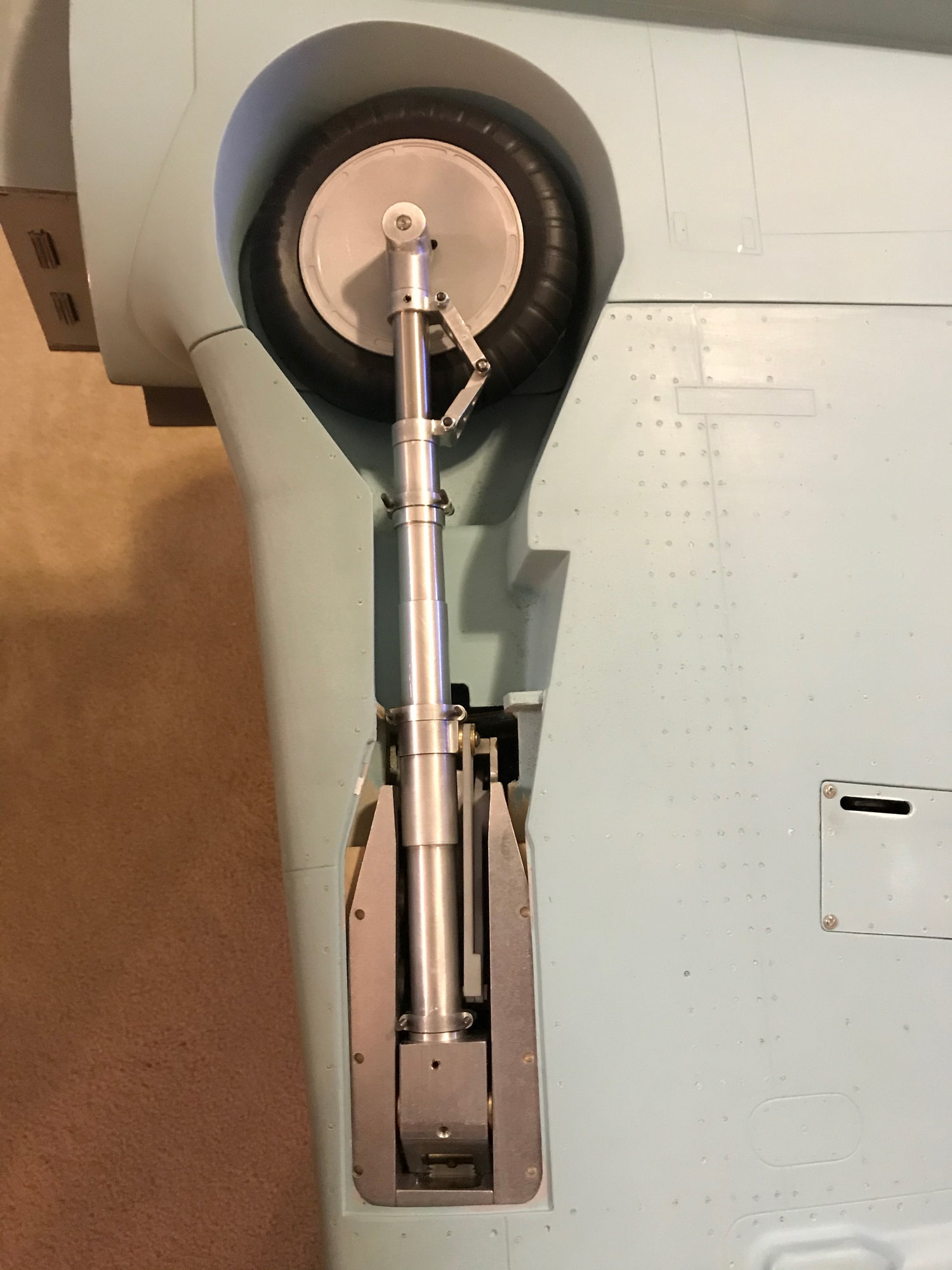
Once I got all the painting out of the way, it was time to start the build process, and the first thing i tackled was the main landing gear. I decided to go w the highly recommended Sierra Retracts SPC Home Page. Looking over the post in this forum, i knew I had to perform some mods to accommodate the mains and tailwheel retracts.

view looking aft
view looking aft
06-07-2020, 01:27 PM
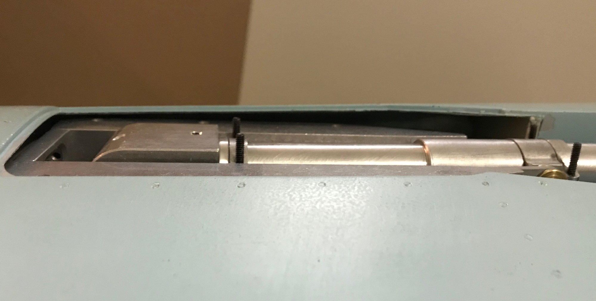
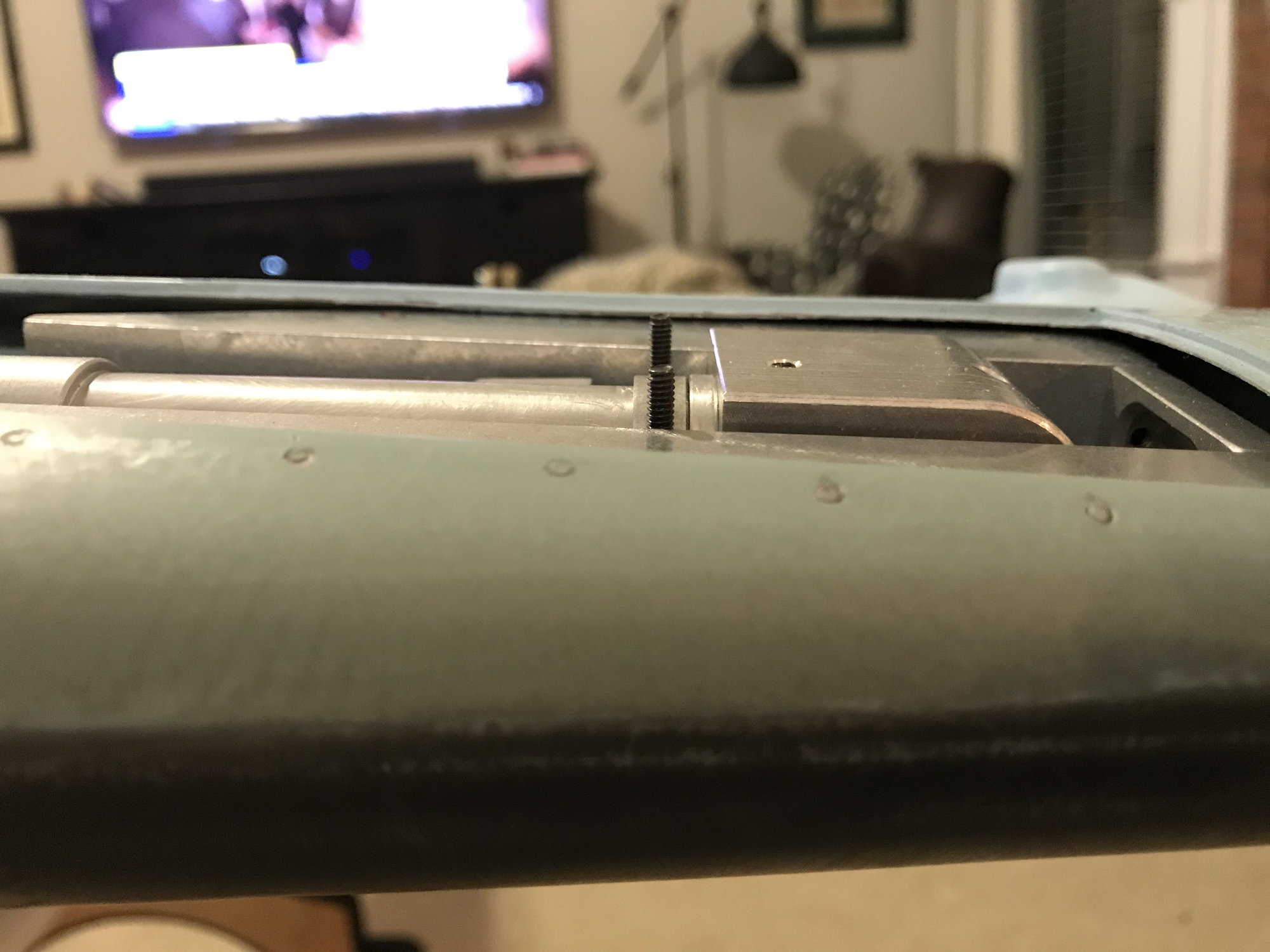
#874
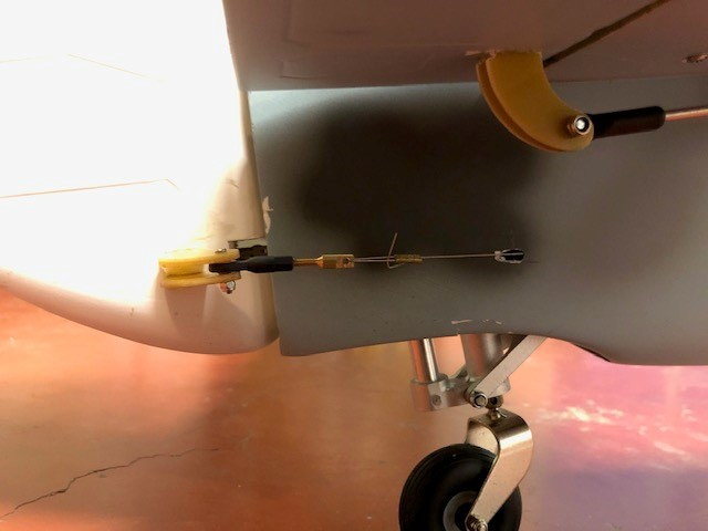
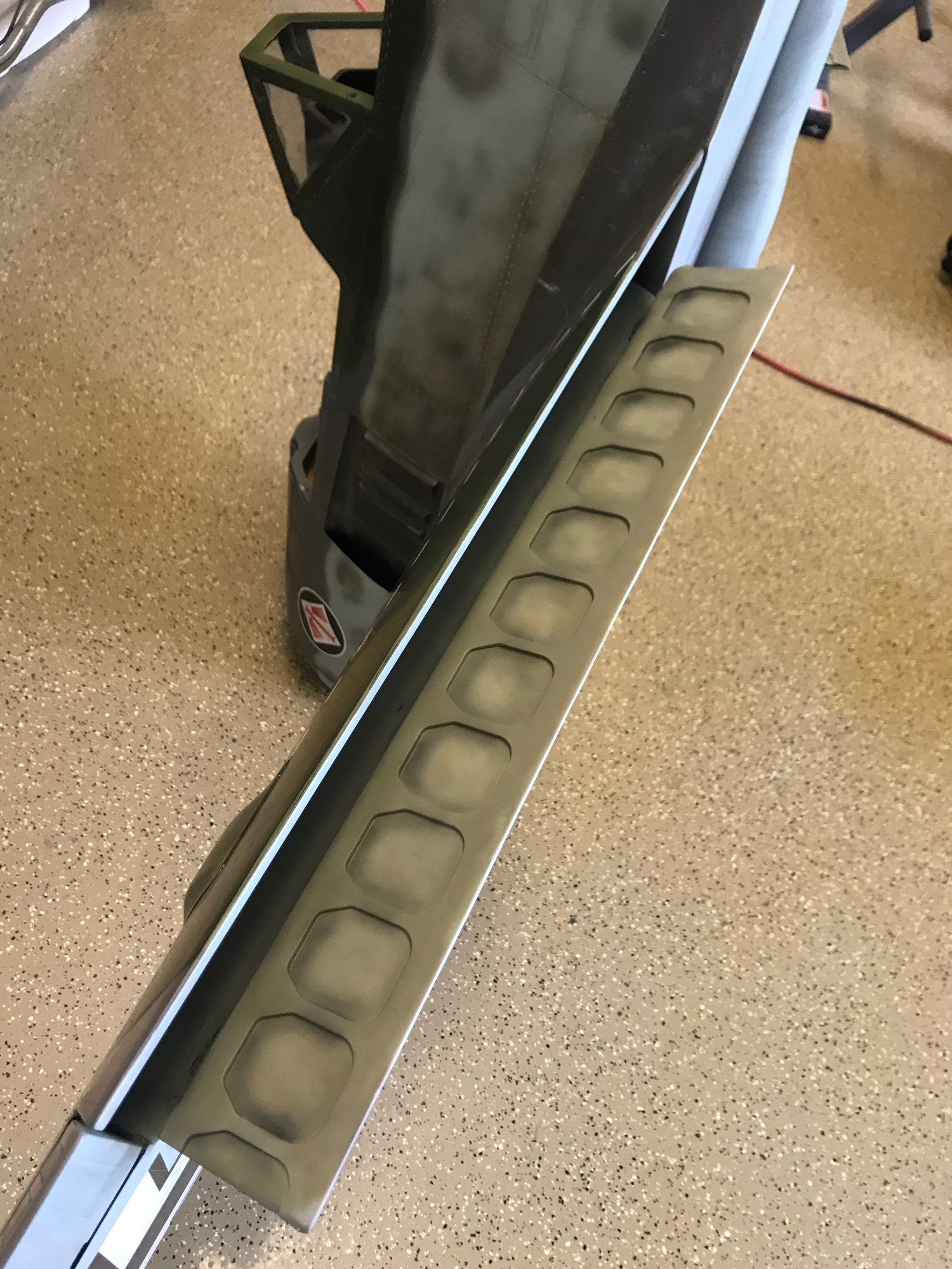
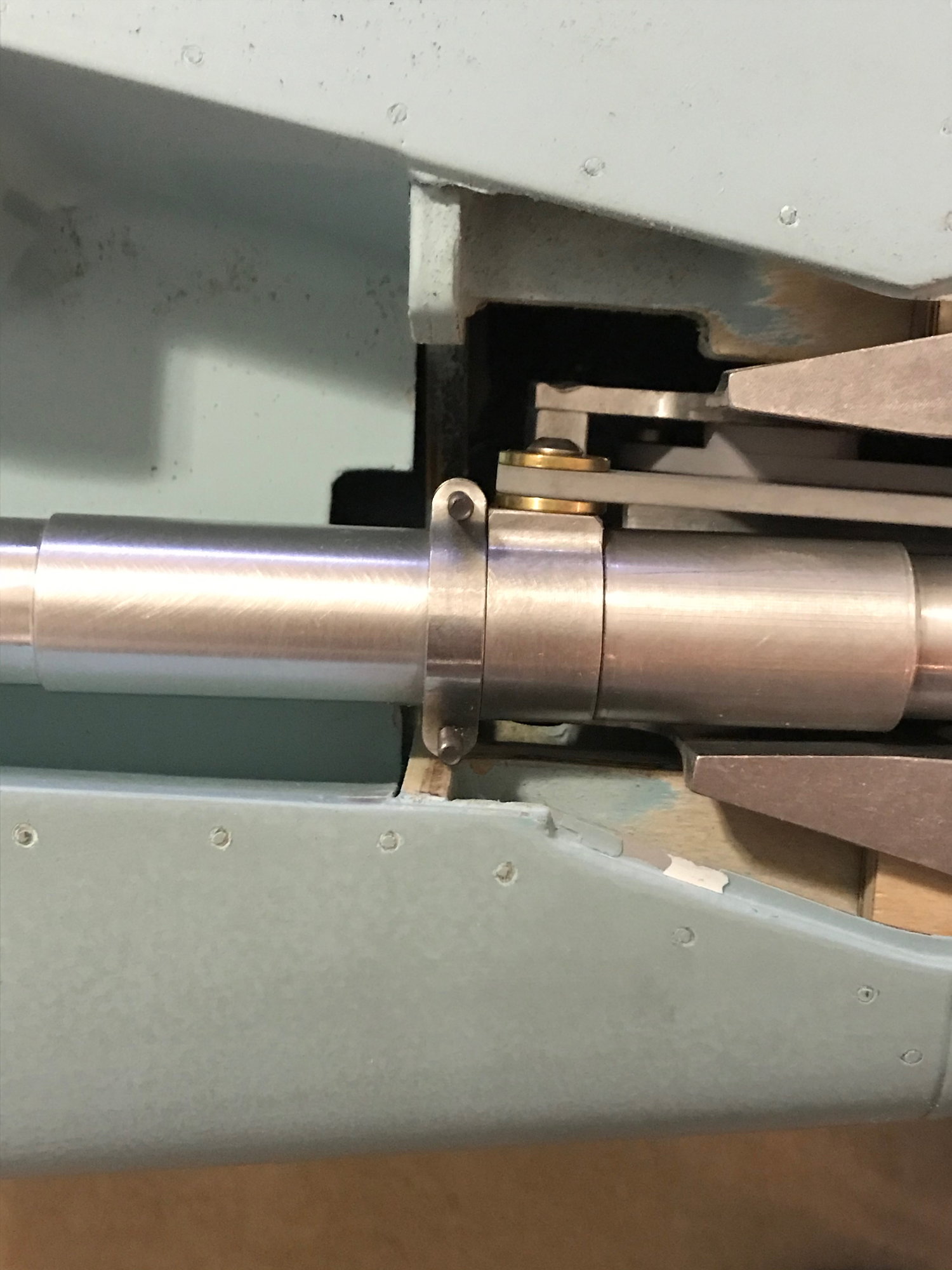
Once satisfied w the main gear install, i moved onto the tail retract. Referring to posts earlier in this thread, i seen where there looked to be a mod to be performed on the tailwheel bulkhead. my kit number is 41 and I did not have to perform such a mod, I just had to determine how high to place the mount in the vertical stab.
Bulkhead before any cutting
Removed the ply from the bulkhead
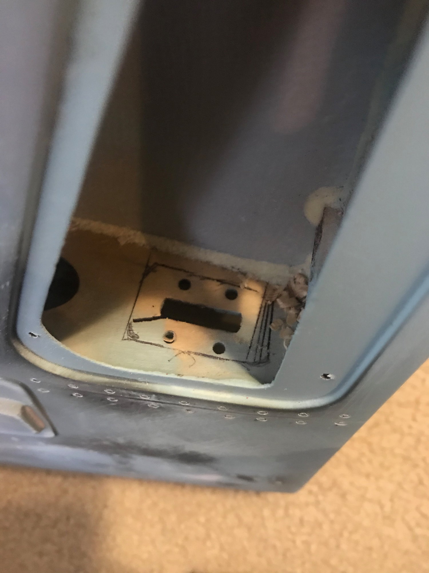
First markings for where i needed to remove more material to accommodate the cylinder
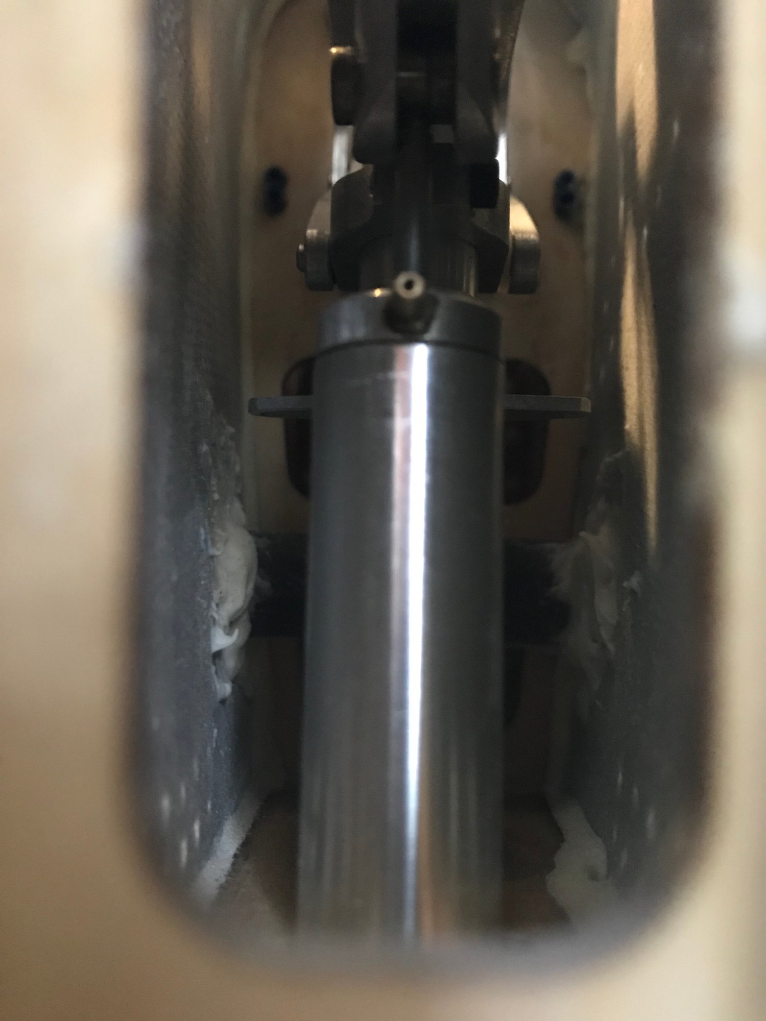
Checking fit and alignment
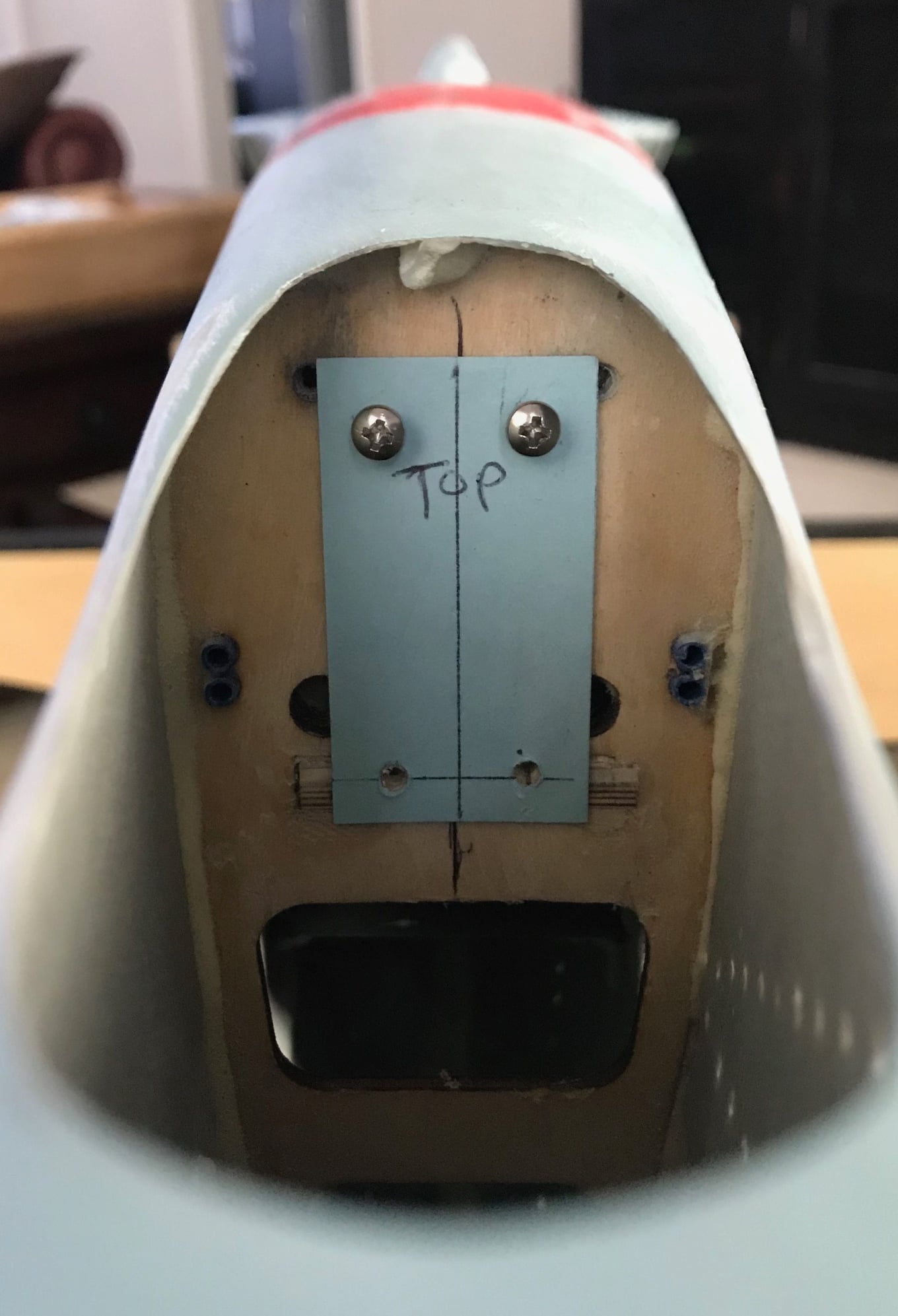
Made a template off the tailwheel retract and centered it up on the bulkhead
Drilled two holes in the rudder post allow a 12" drill bit to pass through to drill new mounting holes on tailwheel bulkhead
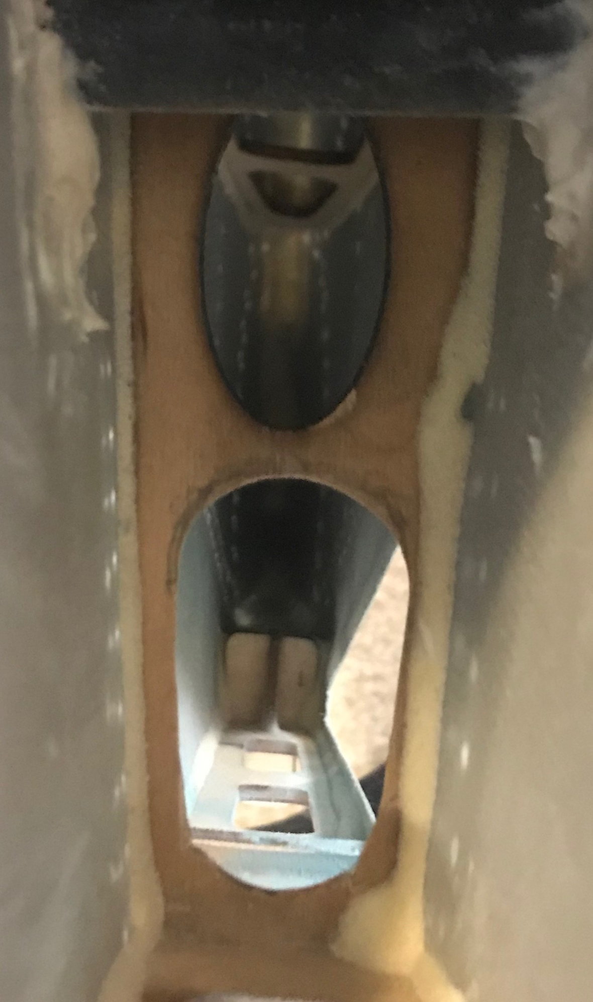
Final cutout to accommodate the cylinder to pass through
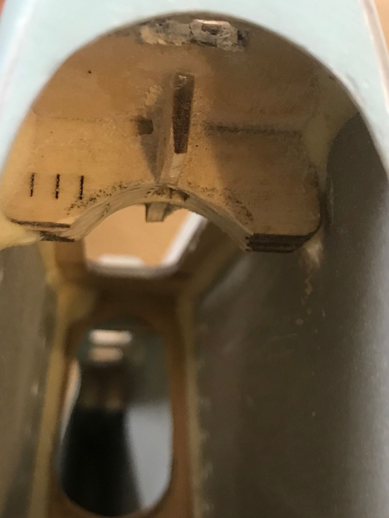
Dremeled a small curve on the rudder post to ensure enough clearance for the cylinder
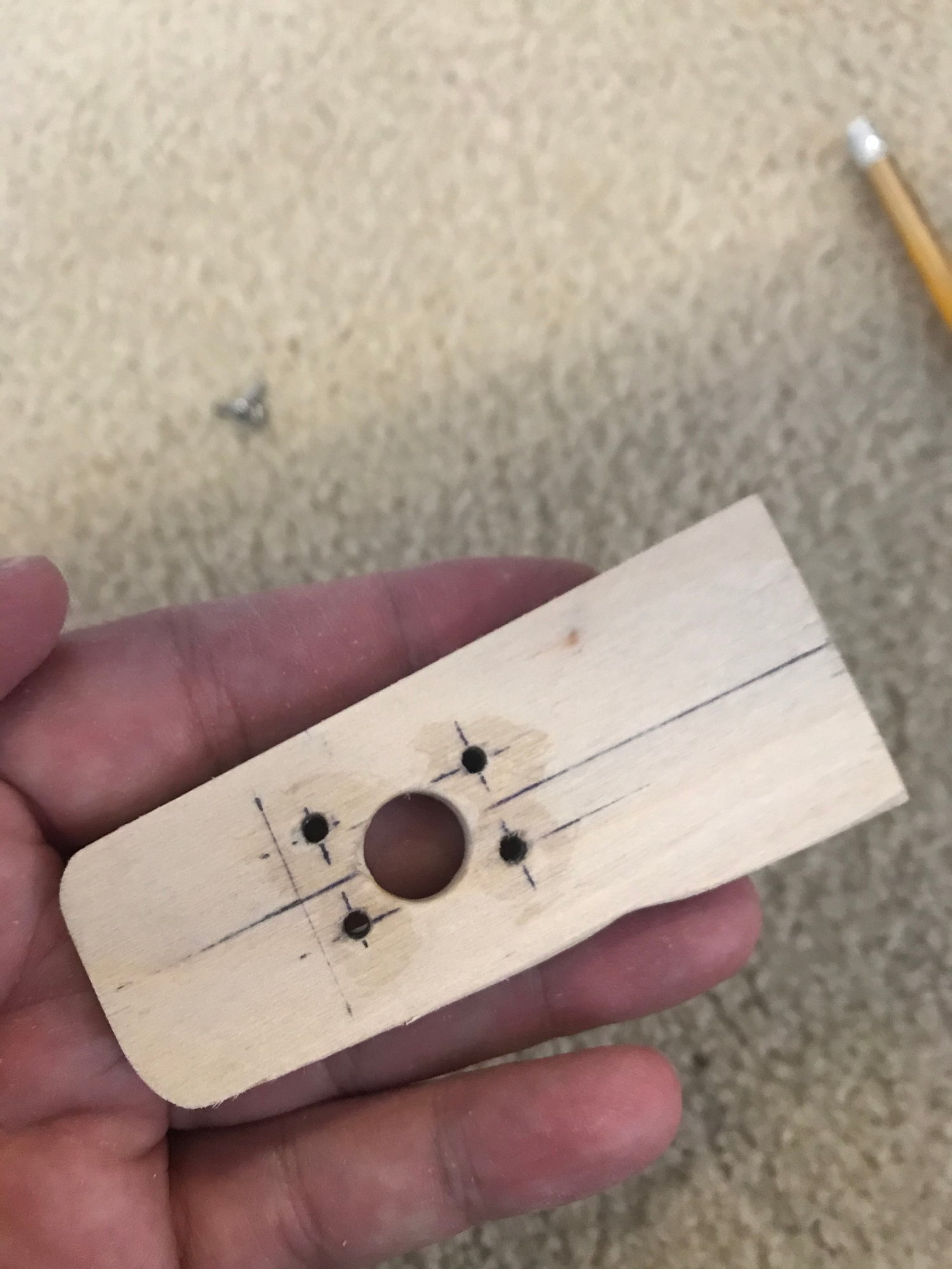
Top mounting plate cut to shape and holes located from the cylinder mount
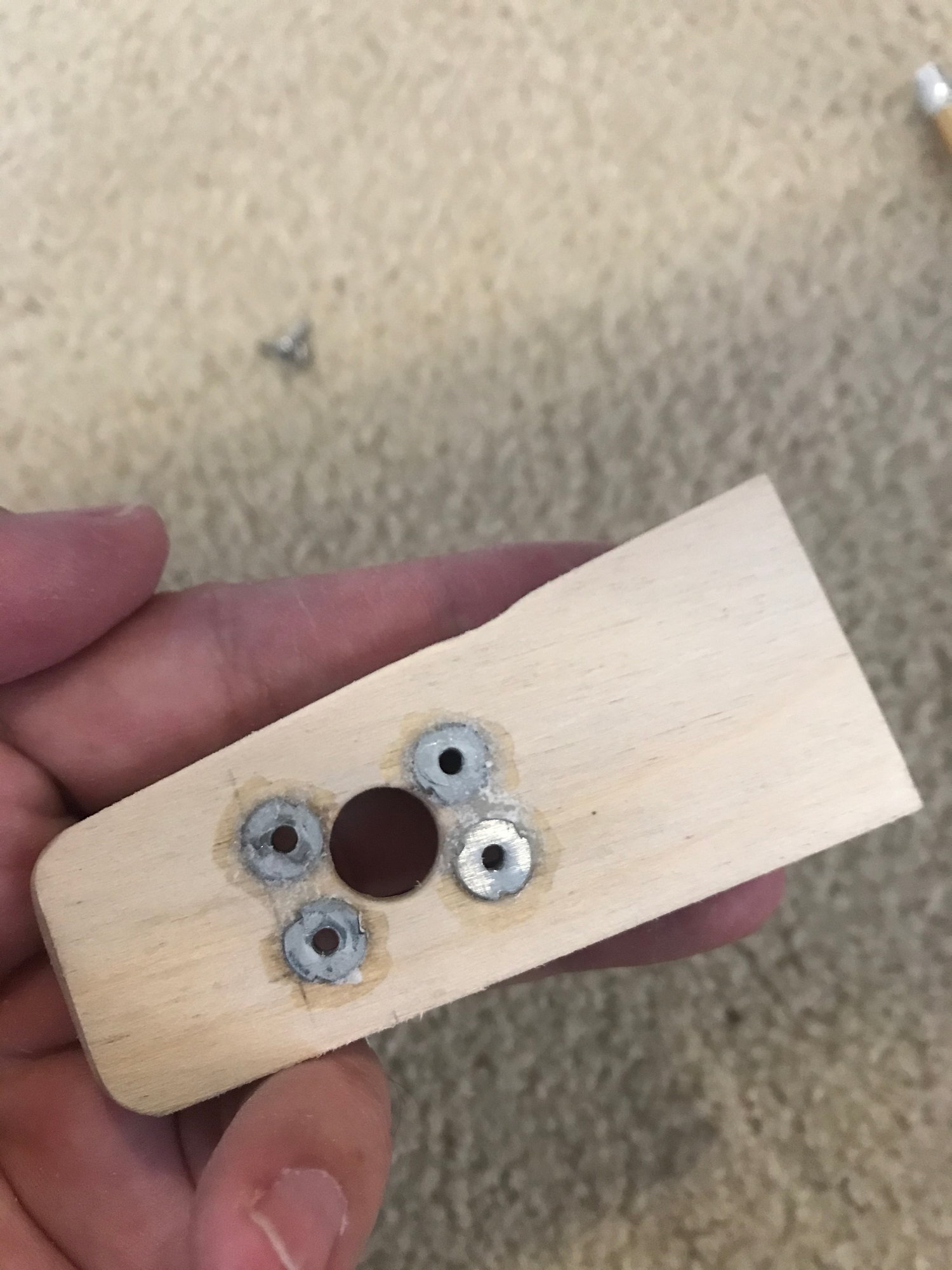
4-40 blindnuts installed
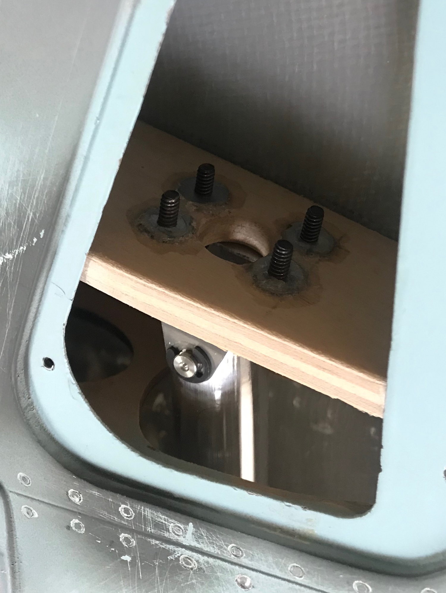
Cylinder top mounting plate being located
Bulkhead before any cutting
Removed the ply from the bulkhead
First markings for where i needed to remove more material to accommodate the cylinder
Checking fit and alignment
Made a template off the tailwheel retract and centered it up on the bulkhead
Drilled two holes in the rudder post allow a 12" drill bit to pass through to drill new mounting holes on tailwheel bulkhead
Final cutout to accommodate the cylinder to pass through
Dremeled a small curve on the rudder post to ensure enough clearance for the cylinder
Top mounting plate cut to shape and holes located from the cylinder mount
4-40 blindnuts installed
Cylinder top mounting plate being located
06-09-2020, 01:56 PM
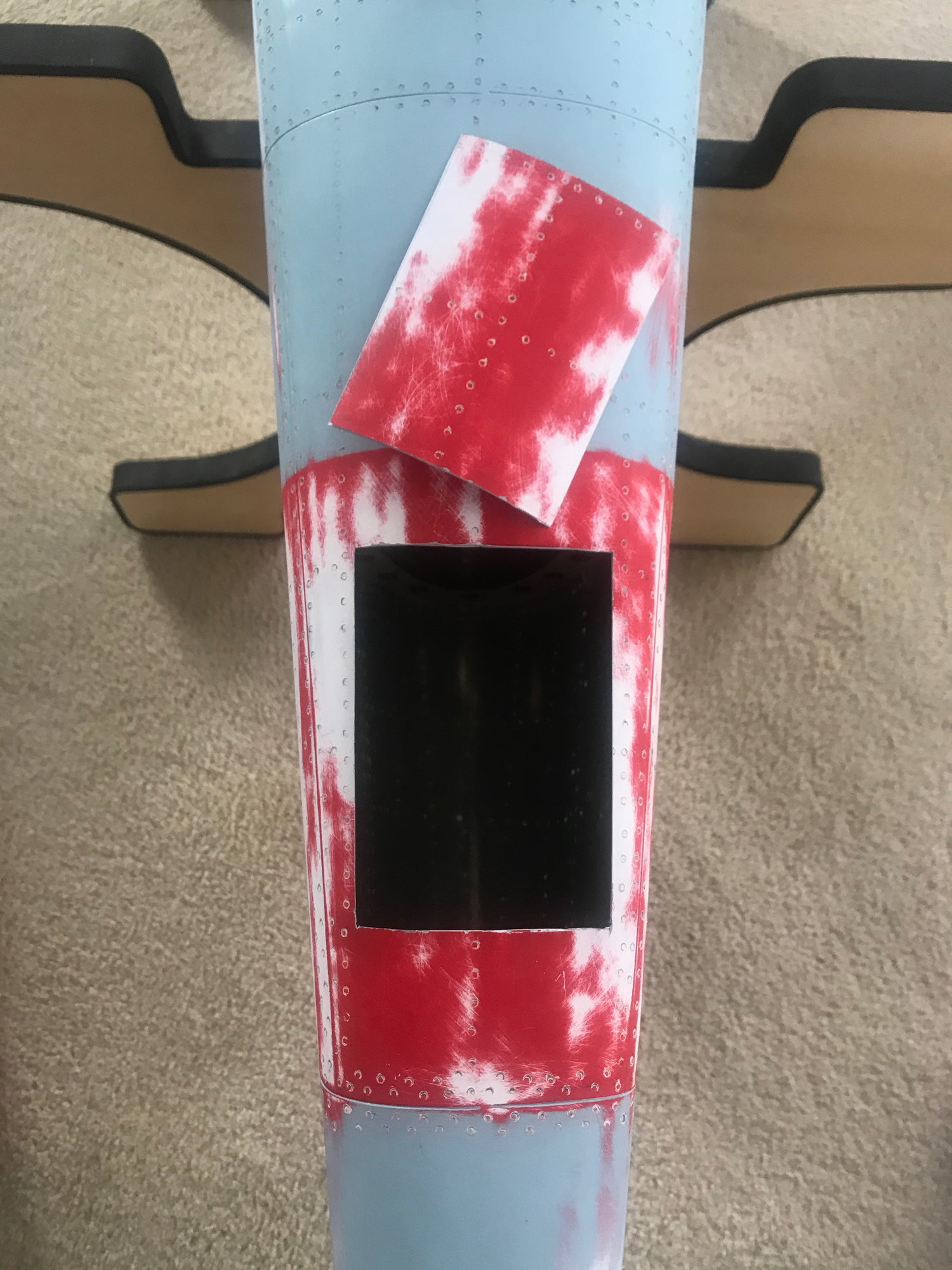
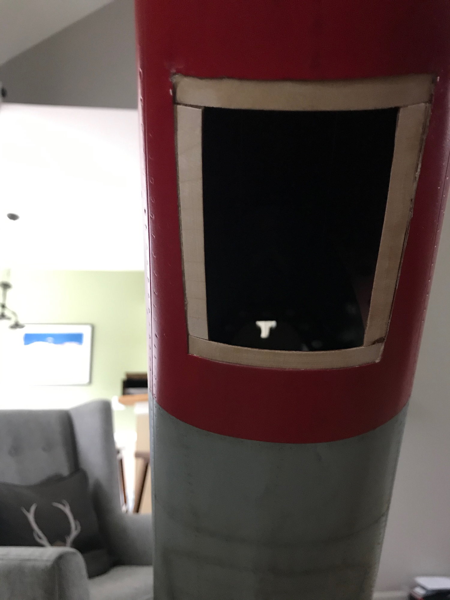
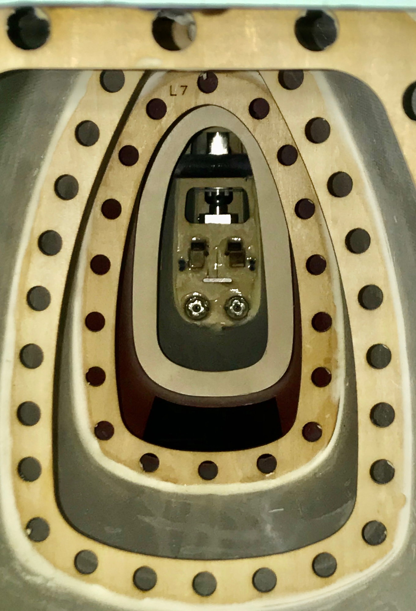
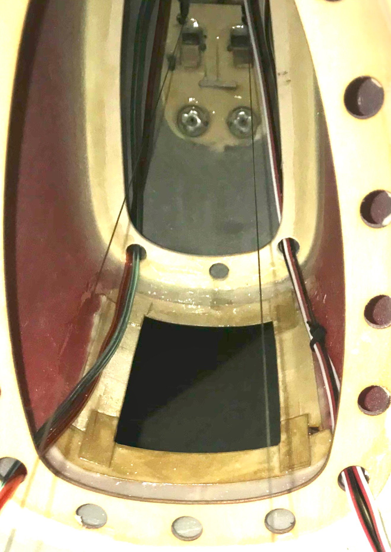
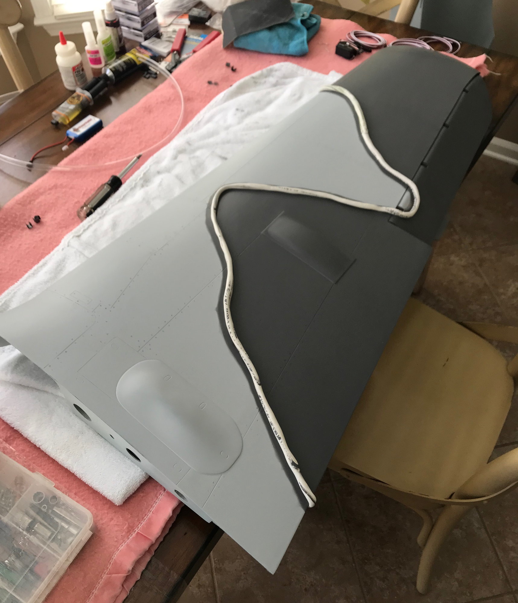
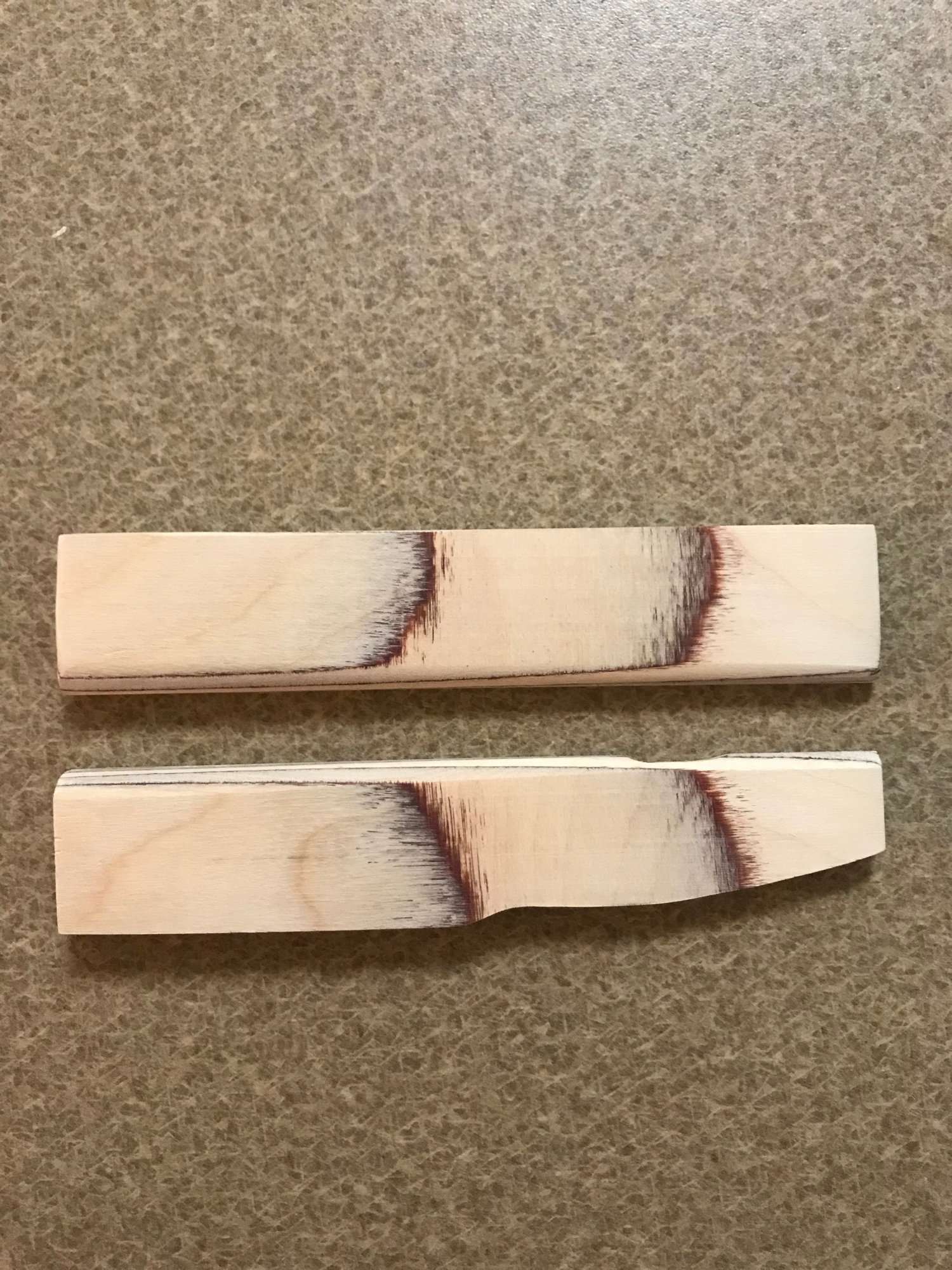
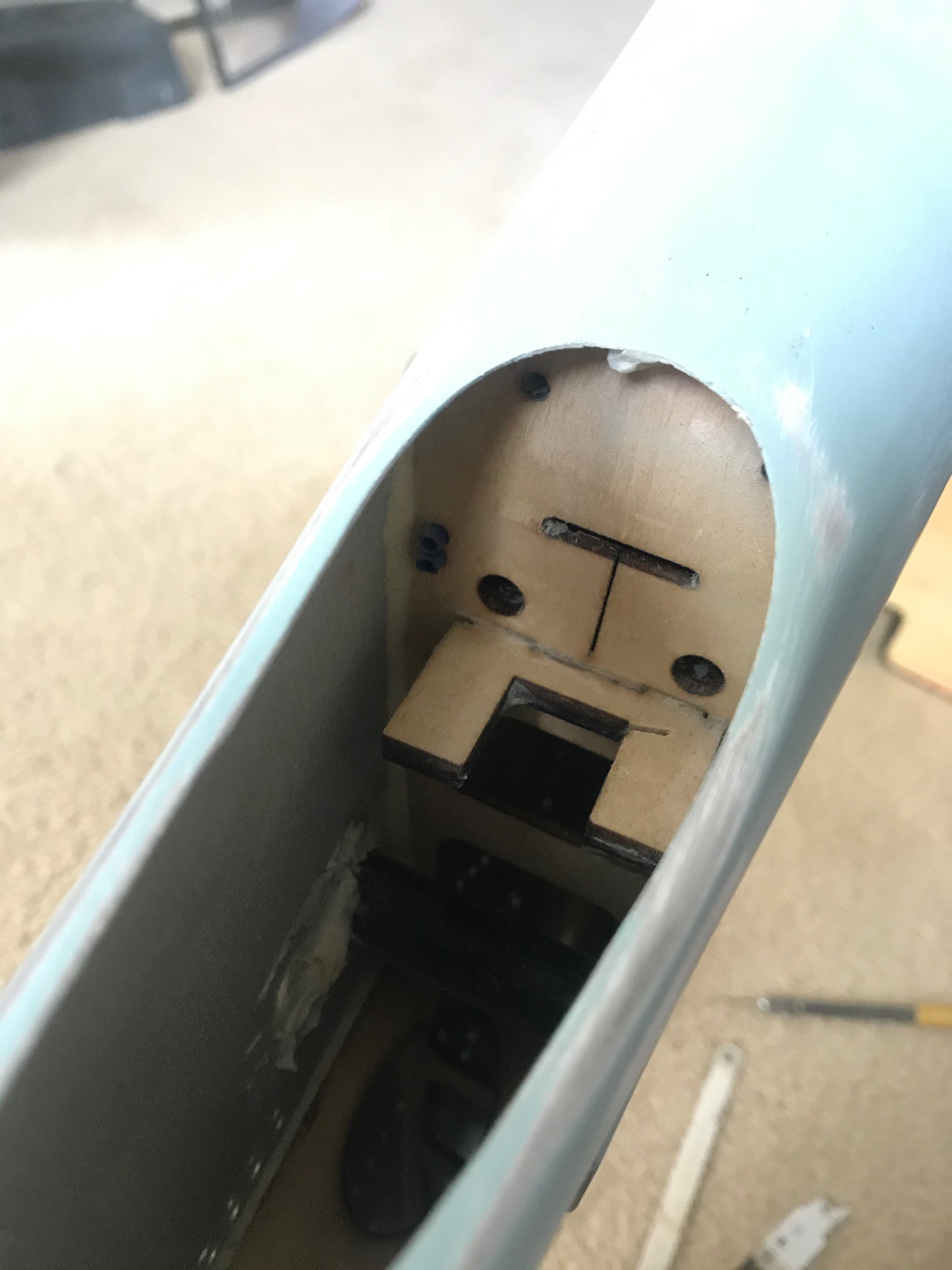
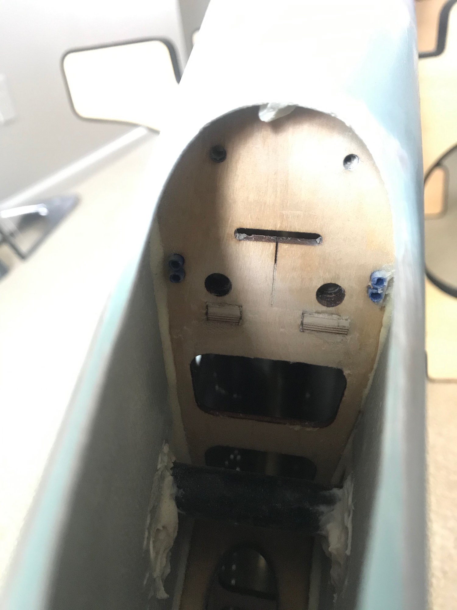
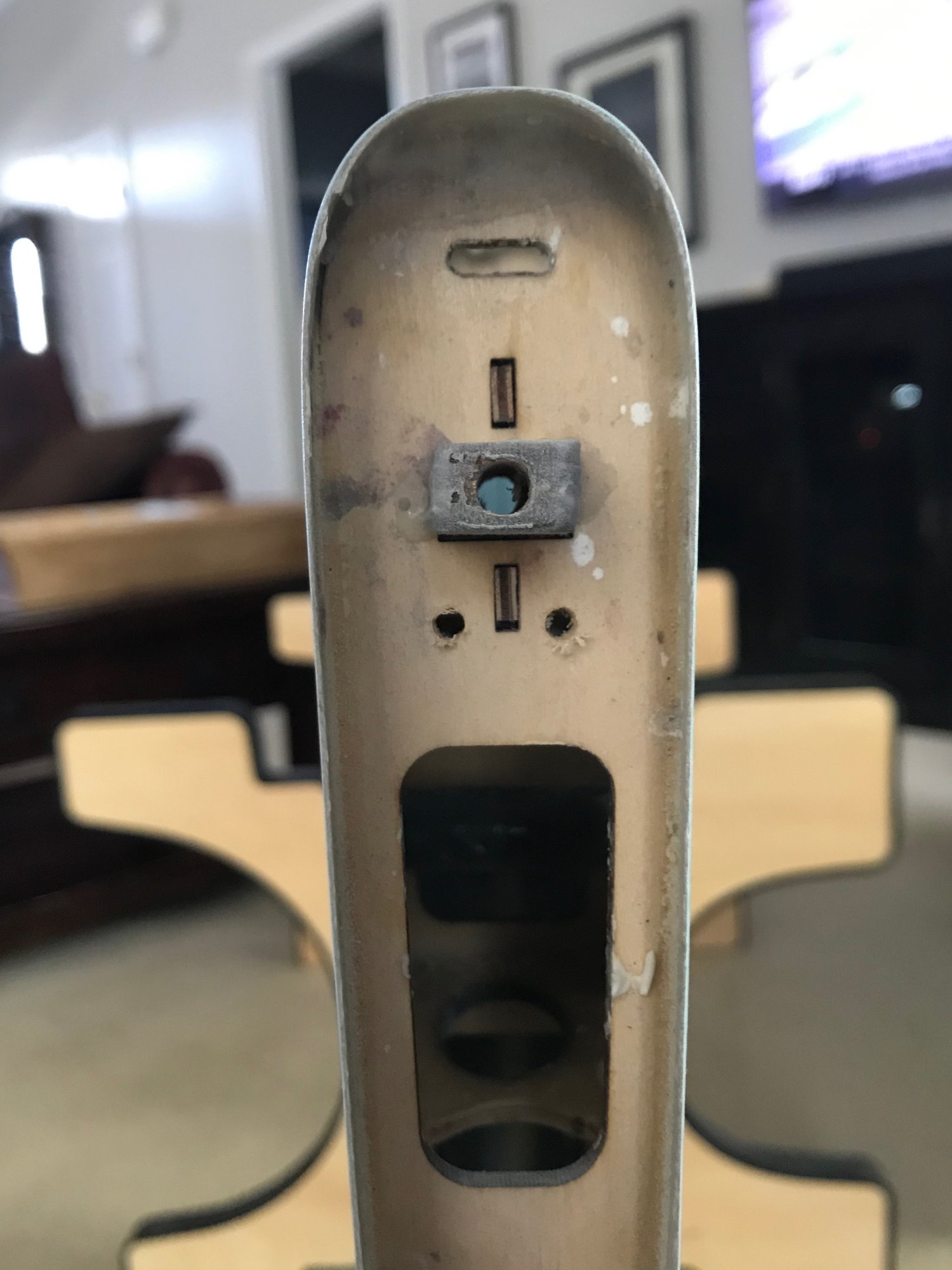
#875
One thing to mention is i ran across a post early on this thread that there was some concern of the area of the fuse where the vertical stab meets the fuselage. Indeed, I felt the same way as there is no former back there and allows for some flexing of the fuselage skins. I know damn well from my days of flying in the Unlimited Class of IMAC that there is concern for fuselage twisting when the aircraft is under high stresses. I know the FW won't go through nearly the amount of stress that i put my aerobatic planes through, but I am not going to let something like this go by me and not try to stiffen the area up a bit.; so I decided to make a former for that area. As a reference for you guys, I placed the former on the aft side of the red stripe on the fuselage. I had cut an access hole on the underside of the fuselage to allow access for installing the former - also, it allows access to the rudder/steering cables and elevator servo wires. In order to get the former shape, I used a contour gauge and transferred it to a piece of 1/8" lite ply - worked like a charm! I then added some 1/32" ply to the fuse so i can make the hatch removable.