


LOCKHEED P-38J “LIGHTNING”. A giant 1/4 scale scratch built model


 07-24-2018, 08:59 AM
#27

Thread Starter

Join Date: Oct 2012
Location: ZARAGOZA, SPAIN
Posts: 97
Likes: 0
Received 0 Likes
on
0 Posts
You may find the thread below interesting if you are not aware of it already.
https://www.rcscalebuilder.com/forum/forum_posts.asp?TID=23228&PN=1
https://www.rcscalebuilder.com/forum/forum_posts.asp?TID=23228&PN=1
07-24-2018, 09:08 AM
#28
Thread Starter
Join Date: Oct 2012
Location: ZARAGOZA, SPAIN
Posts: 97
Likes: 0
Received 0 Likes
on
0 Posts
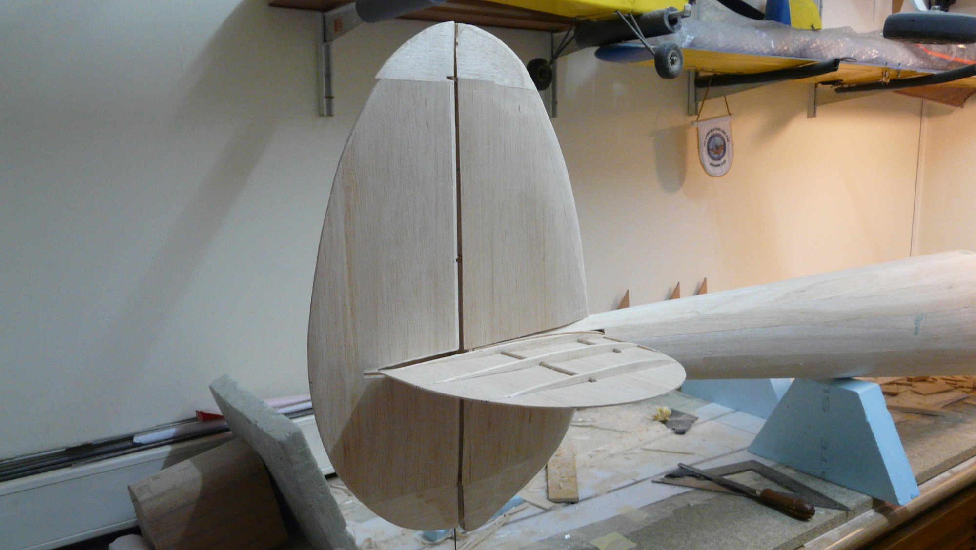
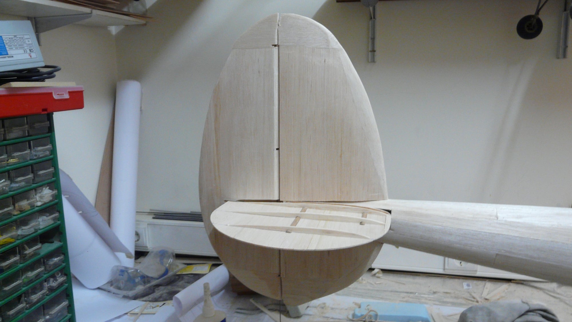
Estabilizer
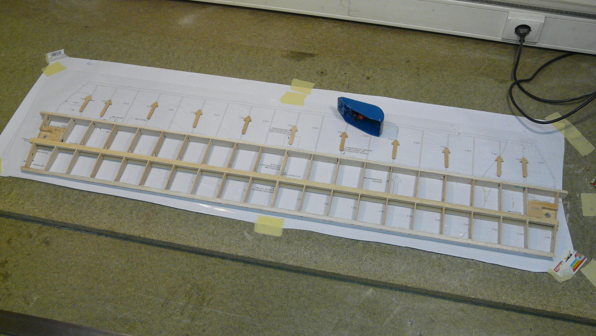
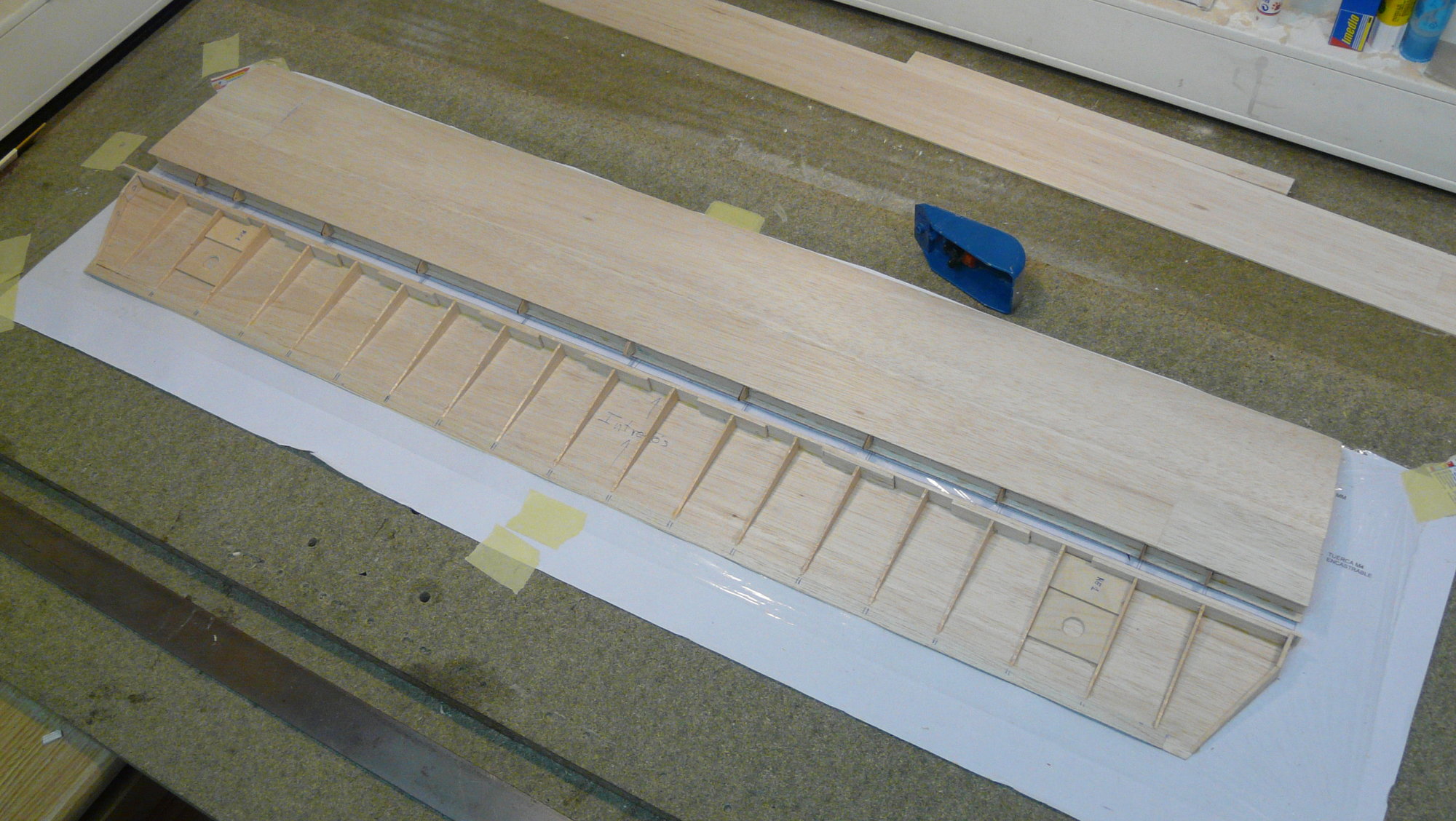
It should be built before the main fuselages, as it is a fundamental piece to ensure a perfect settlement of these on the assembly of the gondola and central wing. It is a light structure of main stringers in samba, with ribs and sheeting of 2 mm.
The symmetrical profile has been provided with a thickness of 10%, in order to locate the two servos of the elevator lying in its interior and obtain a direct control without gaps by not having to manipulate the links in the assembly.
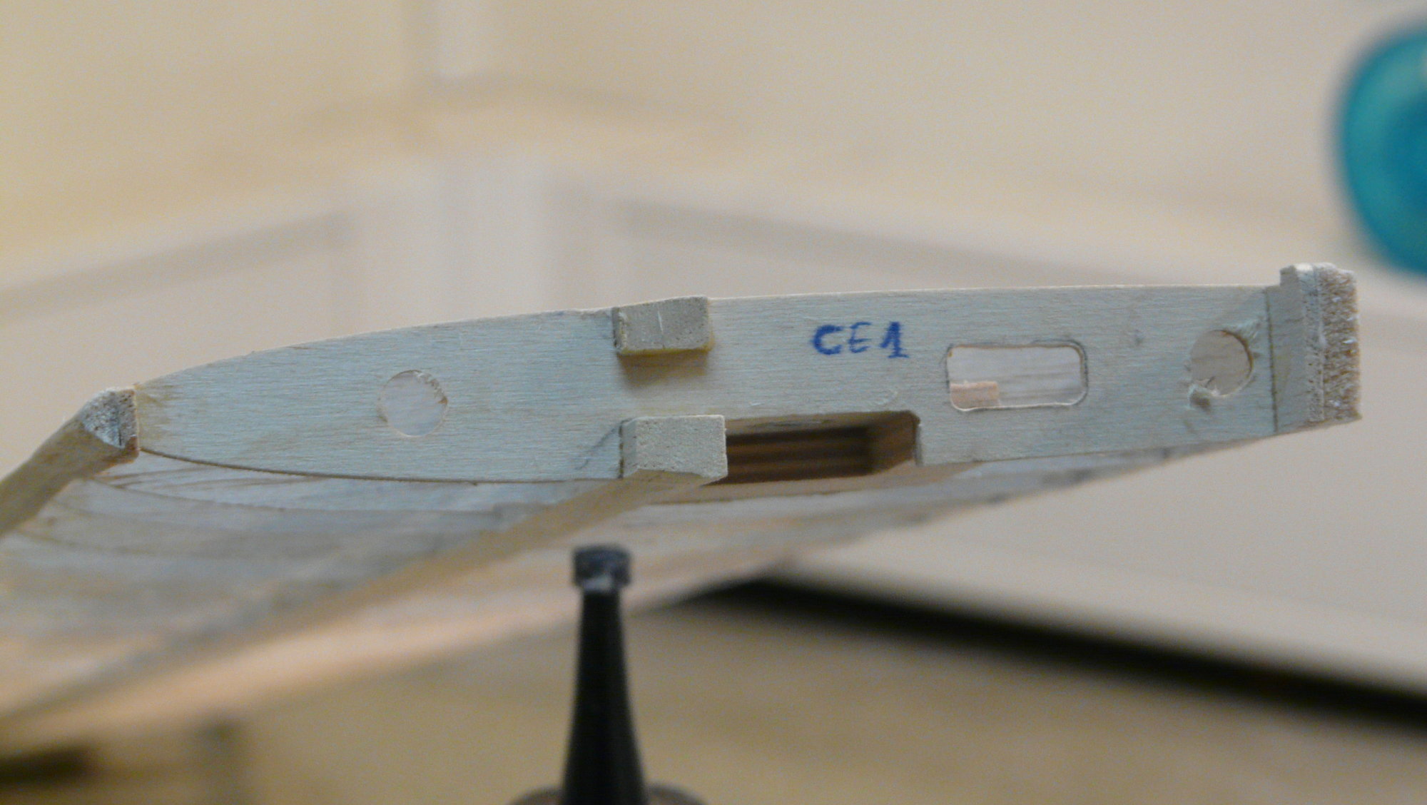
The hinges have been made with 2 mm aeronautical ply attached to the ribs of the fixed part, crossed by a 1.5 mm steel rod shaft. This axle runs through the interior of a Sullivan Gold-N-Rod® yellow polygonal transmission that fits into the moving part. If another type of more conventional hinges is preferred, the plane will have to be reinforced conveniently. With this choice, I can disassemble the elevator easily by removing the rod from the side.
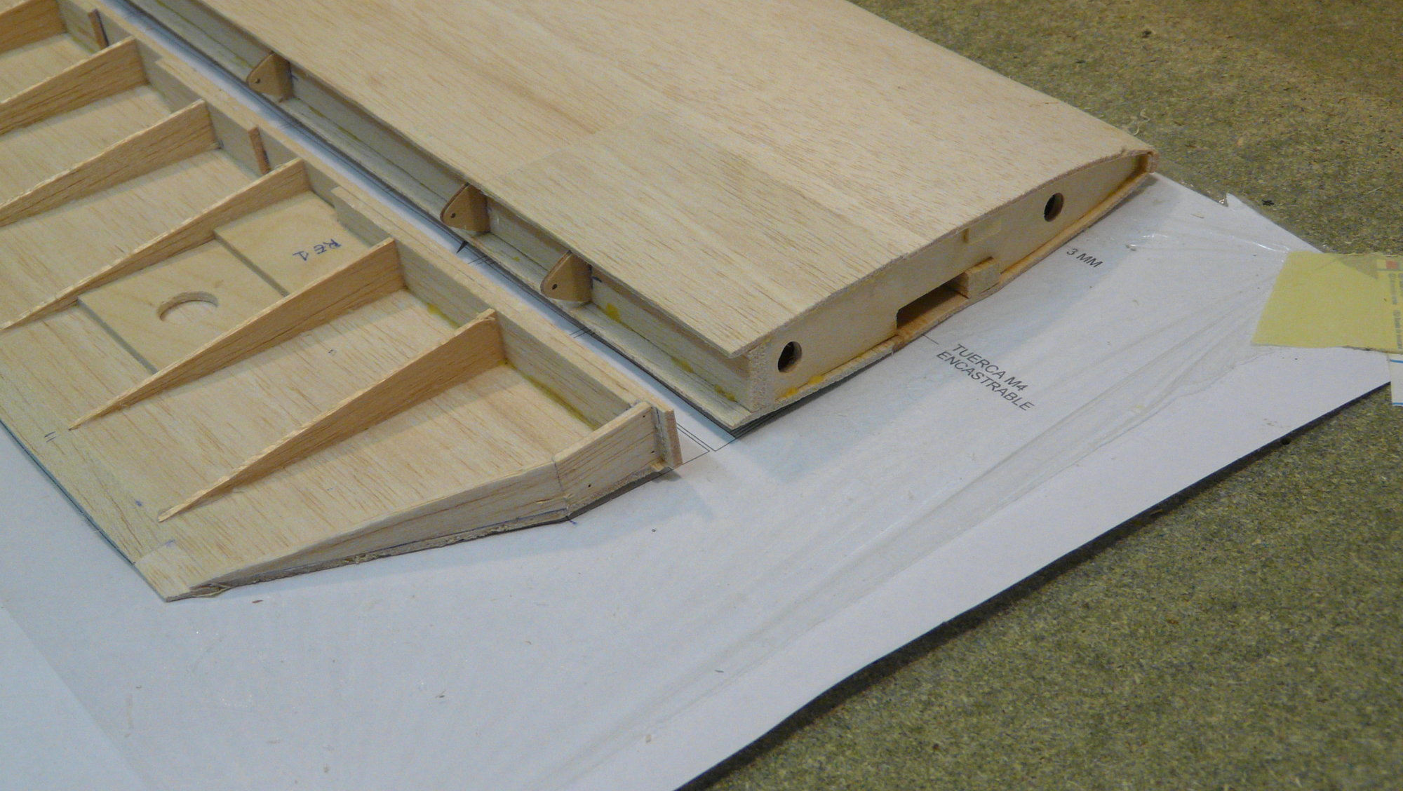
The fixation to the fuselages has been solved with four beech dowels and two M4 self-powered nuts.
Last edited by fbielsa; 07-24-2018 at 09:26 AM.
 07-30-2018, 06:24 AM
#30
Thread Starter
Join Date: Oct 2012
Location: ZARAGOZA, SPAIN
Posts: 97
Likes: 0
Received 0 Likes
on
0 Posts
Fuselages
As both fuselages are almost identical, I also recommend building them simultaneously.
In this case, two mounting boards are required, about 250 x 40 cm (100''x18''), and caution to clearly differentiate the right and the left when applying the reinforcements of the wing seats, the benches of the landing gear, the engine and the seats of the horizontal stabilizer, that go to mirror in each one of them. Take care with the difference in the lateral incidence of the normal rotation engines for the construction of their benches: left at 0 degrees, right at 2 degrees on the right (in the case of using a counter-rotating engine on the right side, the two benches should go to 0 degrees). Both engines are set with 4 degrees of positive incidence, with respect to the horizontal of the fuselage assembly crutch.
Here we go with them..
08-02-2018, 02:48 AM
#31
Thread Starter
Join Date: Oct 2012
Location: ZARAGOZA, SPAIN
Posts: 97
Likes: 0
Received 0 Likes
on
0 Posts
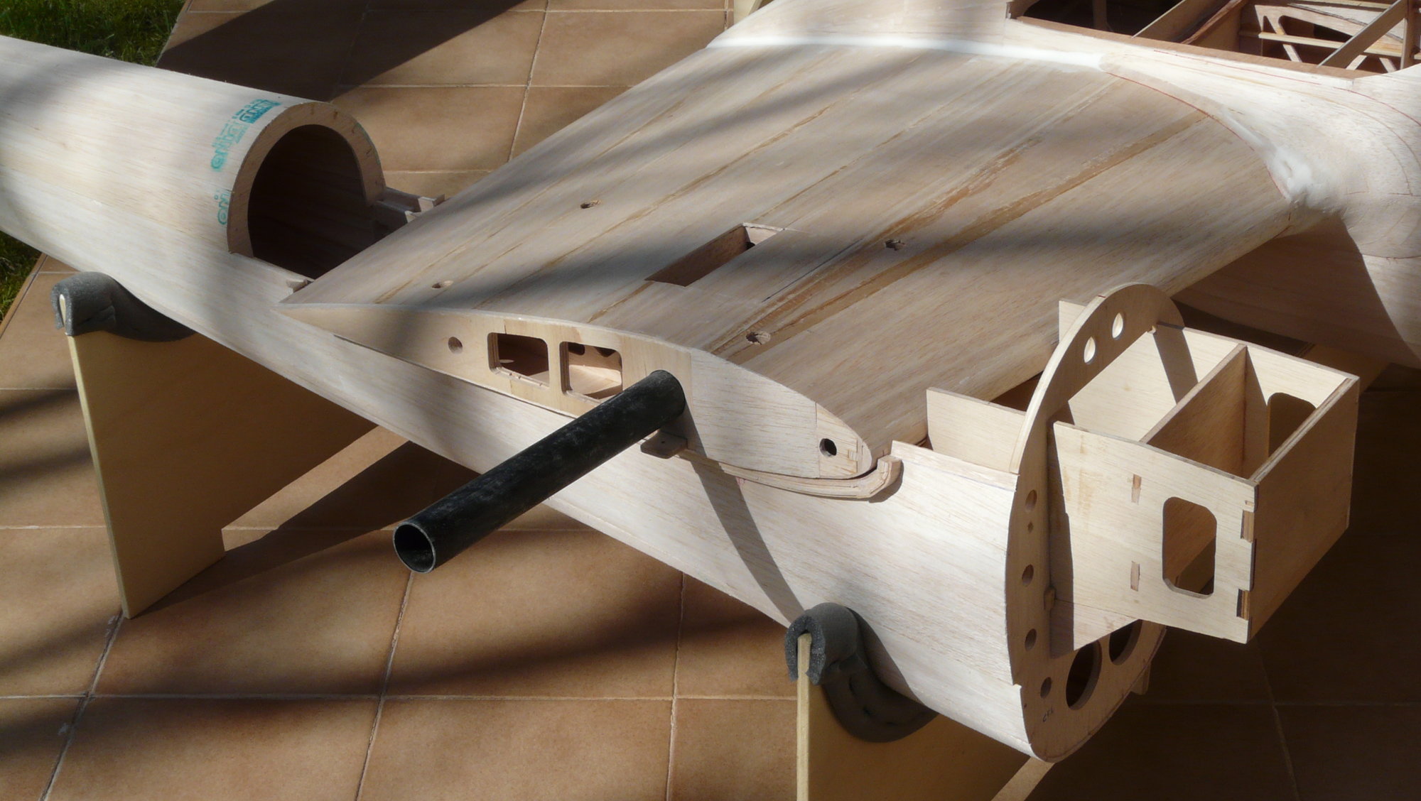
The assembly is similar to that of the central nacelle, that is, on a crutch based on samba stringers in which the 3 mm ply formers (1/8'') and their 3 x 7 mm samba spars are applied. It does not present a special complication, except in the gluing of all the reinforcements that make up the wing seat, and in the positioning of the formerss inclined 5 degrees with respect to the horizontal of the crutch (at 90 degrees with respect to the upper line of the fuselage). For information purposes, the wing at this point has a positive incidence of about 7 degrees with respect to the mains spars of the crutch.
General view of the crutch
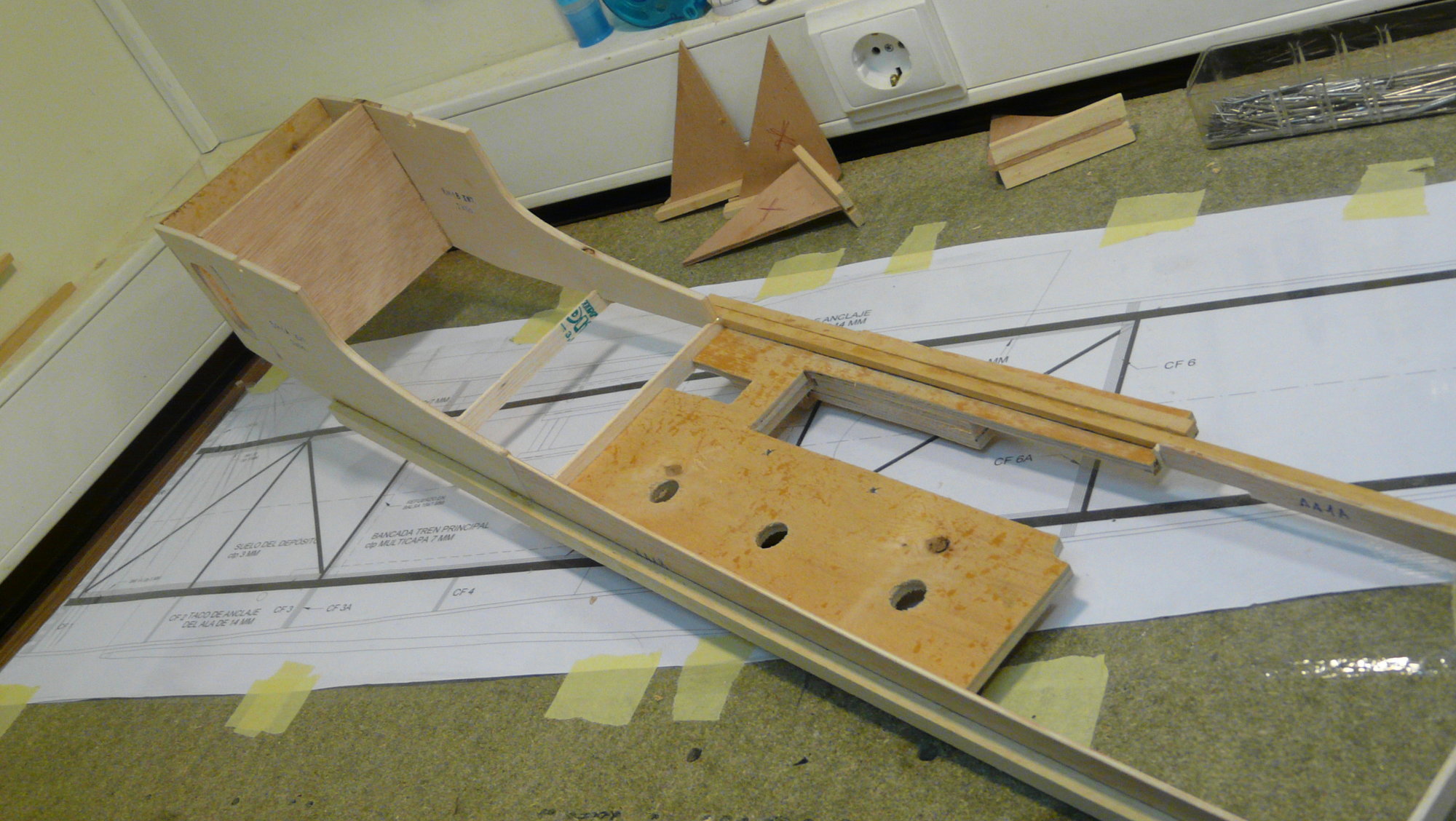
Engine and main landing gear bench
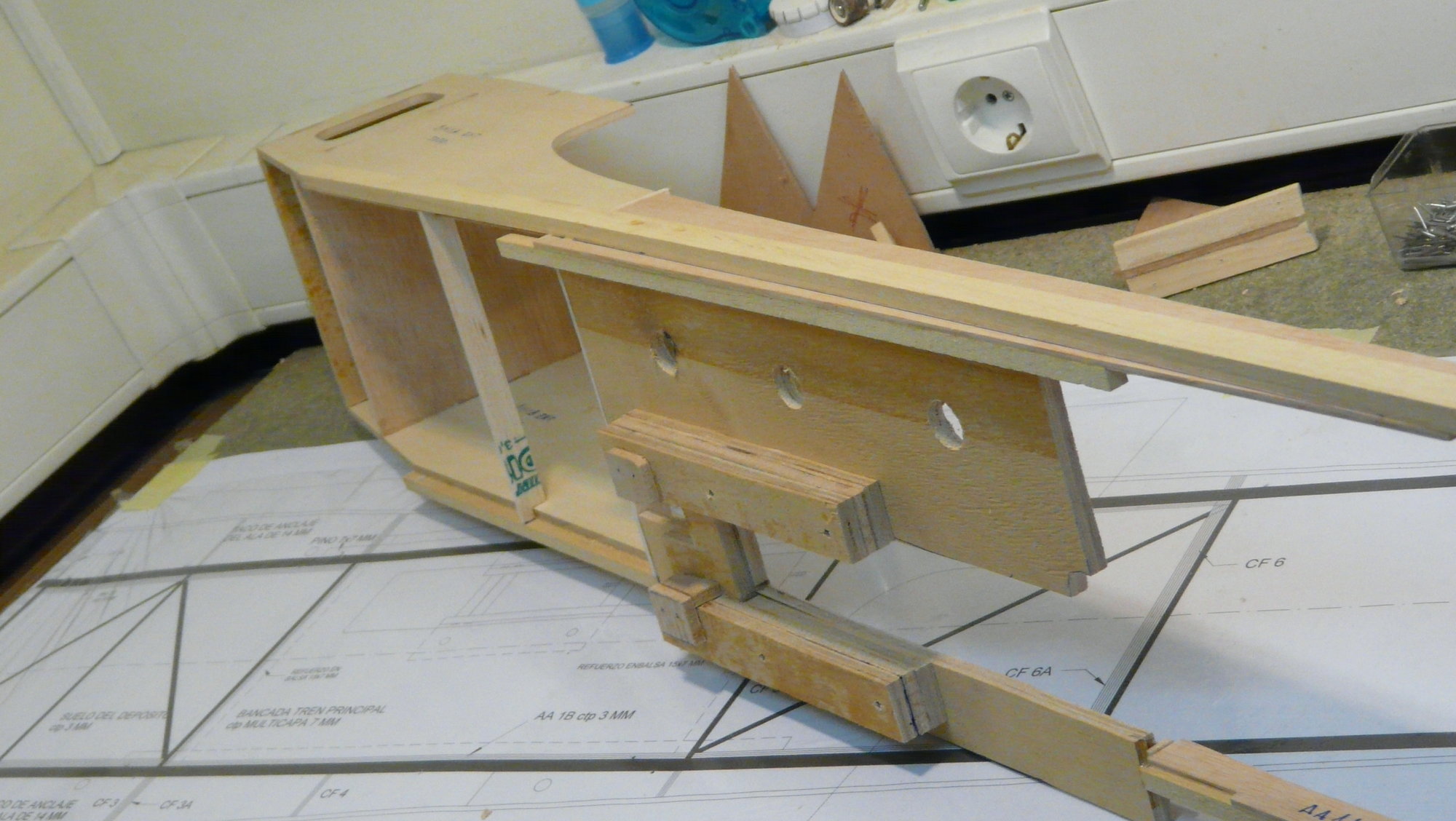
Reinforcements for receiving stabilizer
General view of the crutch
Engine and main landing gear bench
Reinforcements for receiving stabilizer
 08-07-2018, 08:33 AM
#33
Thread Starter
Join Date: Oct 2012
Location: ZARAGOZA, SPAIN
Posts: 97
Likes: 0
Received 0 Likes
on
0 Posts
The plans are self-drawn using a CAD app. This process took me 6 months, So, it is not a comercial kit but a scratch buid project. Fortunately, I had the chance to cut all the ribs and frames with a CNC milling machine in a friend's workshop.
Keep in mind that there are more than 300 pieces. A lot of work to do it by hand.
08-07-2018, 08:52 AM
#34
Thread Starter
Join Date: Oct 2012
Location: ZARAGOZA, SPAIN
Posts: 97
Likes: 0
Received 0 Likes
on
0 Posts
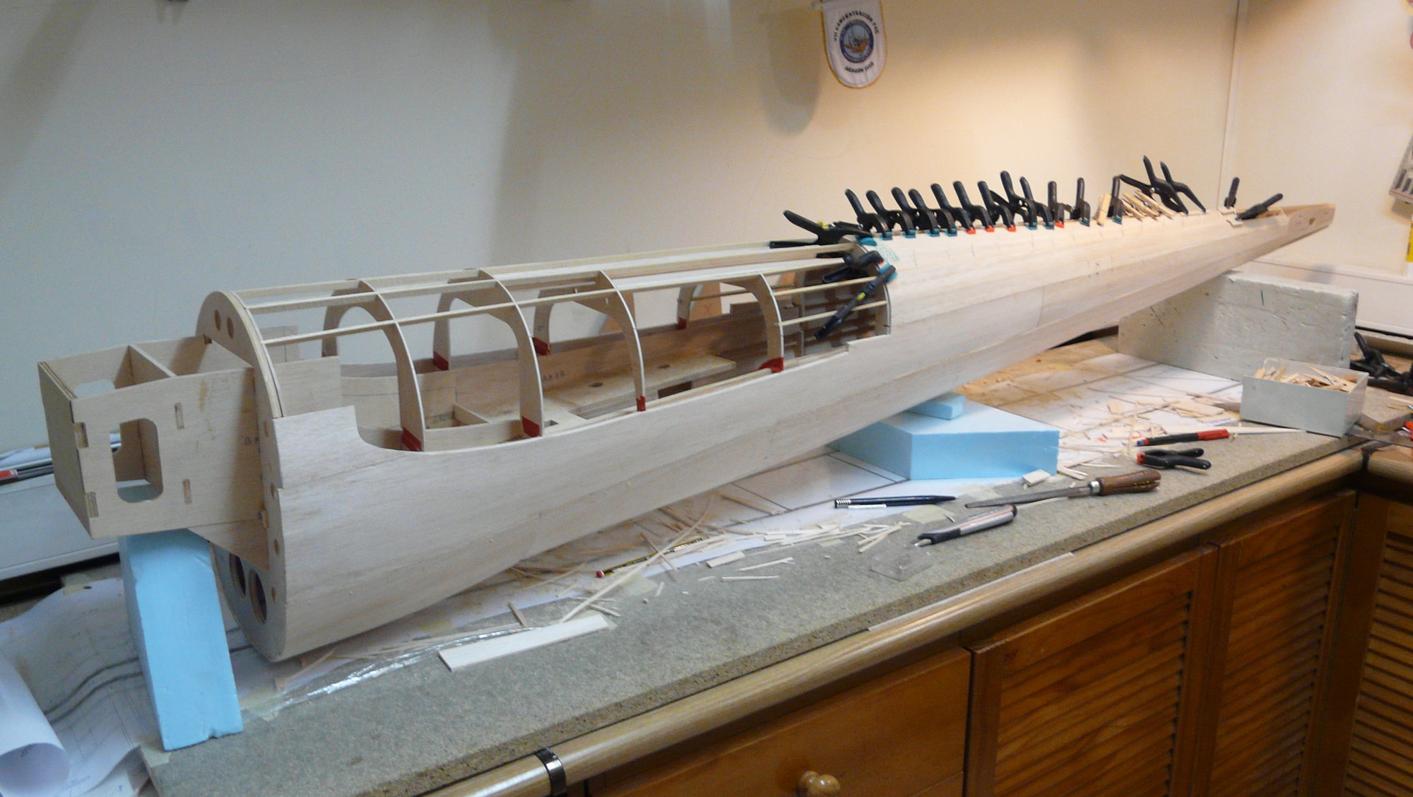
Following with the fuses...some pics of several steps of the process.
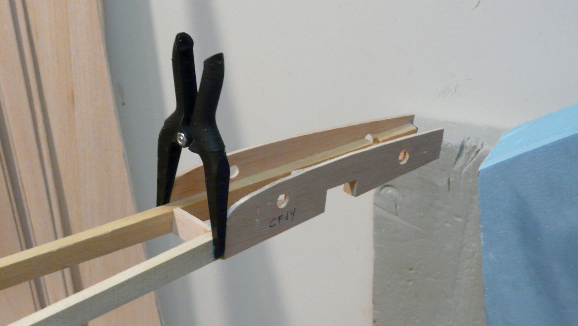
Note that there is no difference with the way you build any classic fuselage, but the size and perfection of the alignments make the task enormously difficult.
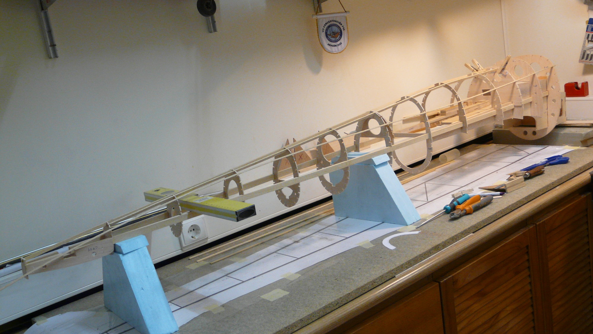
The crutch ready to receive formers and stringers
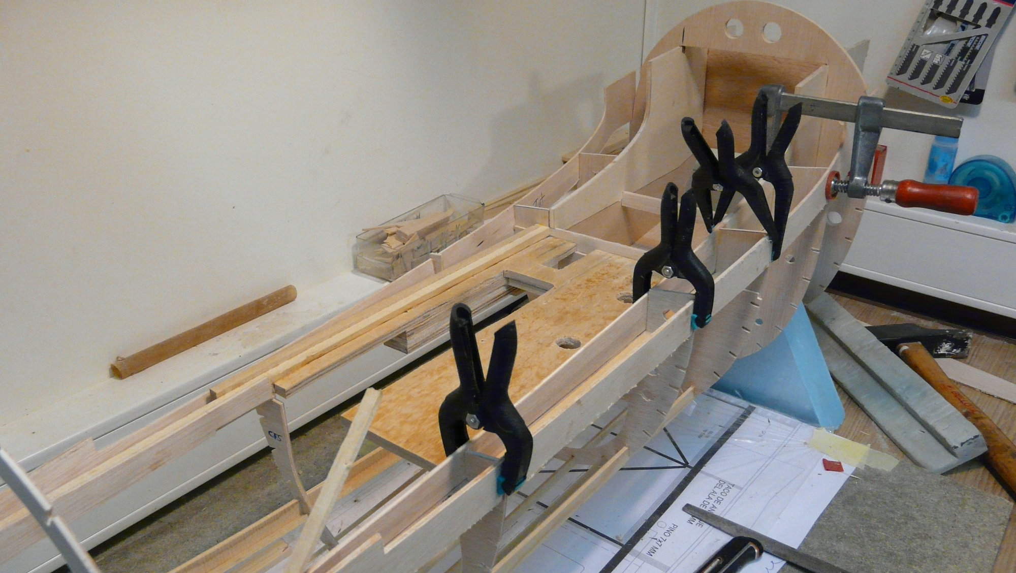
Gluing the wing base reinforcements
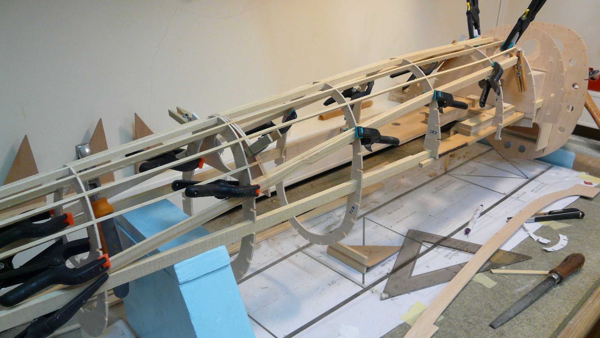
More and more stringers. This time gluing the gear doors ones
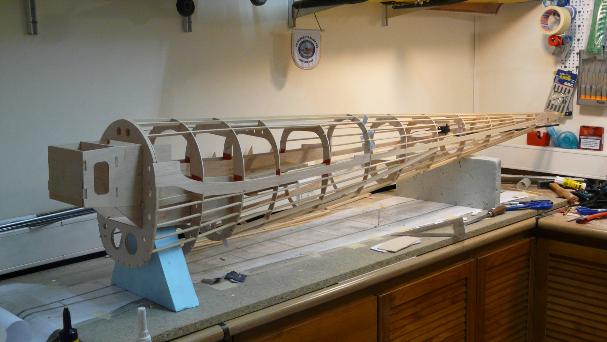
One fuselage ready to be sheeted
As I said in a post above, I recommend building both fuselages at the same time, in two different workbenches. You will save a significant amount of time
Note that there is no difference with the way you build any classic fuselage, but the size and perfection of the alignments make the task enormously difficult.
The crutch ready to receive formers and stringers
Gluing the wing base reinforcements
More and more stringers. This time gluing the gear doors ones
One fuselage ready to be sheeted
As I said in a post above, I recommend building both fuselages at the same time, in two different workbenches. You will save a significant amount of time
08-15-2018, 10:31 AM
#37
Thread Starter
Join Date: Oct 2012
Location: ZARAGOZA, SPAIN
Posts: 97
Likes: 0
Received 0 Likes
on
0 Posts
Hi, mates.
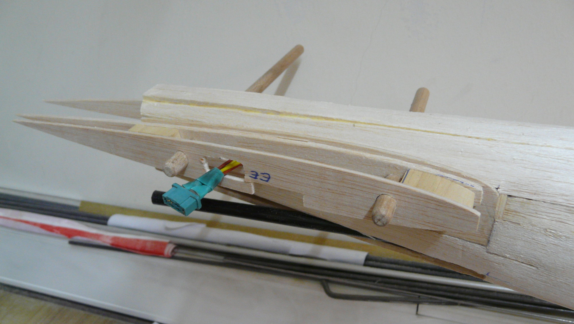
Going on with the thread. As you can see, I have chosen to mount each rudder servo halfway along the length of the fuselage, which, once covered, will be under a trapdoor accessible from the inners radiators, in order to avoid ballasting the nose (we have already seen that those of elevator go inside the plane of stabilizer). I used special high-strength Sullivan Gold-N-Rod® transmission (S518 / 4-40) for this purpose.
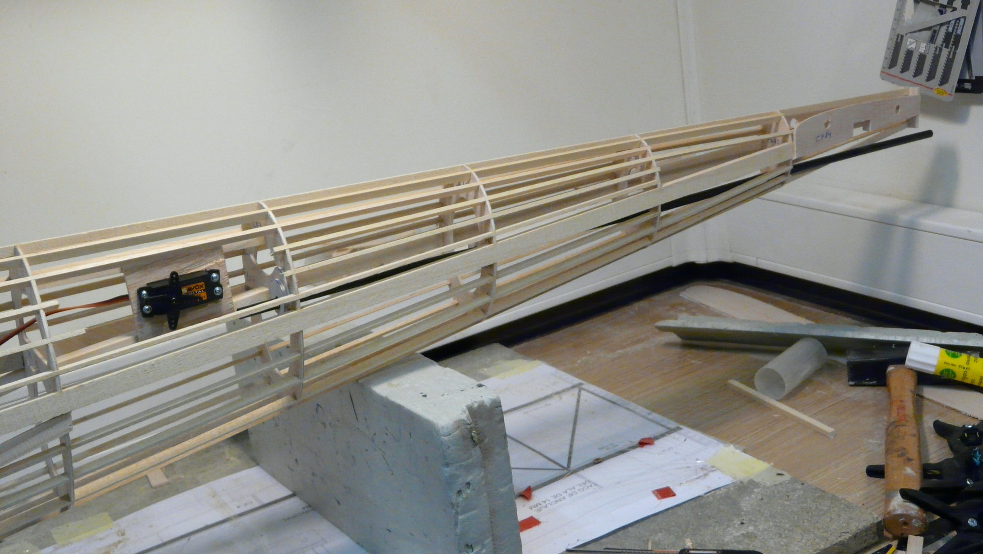
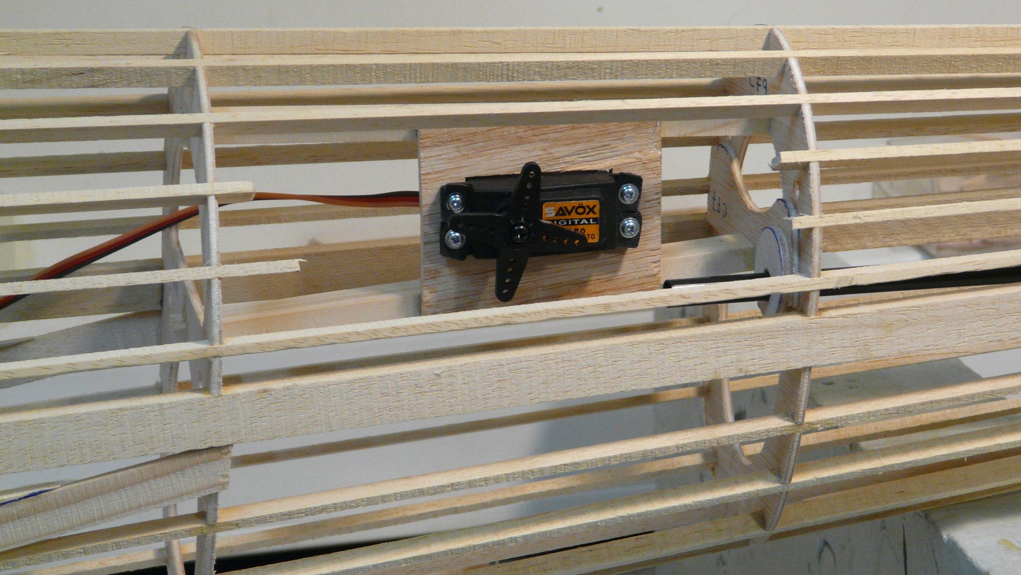
Closed view of the right rudder servo
Going on with the thread. As you can see, I have chosen to mount each rudder servo halfway along the length of the fuselage, which, once covered, will be under a trapdoor accessible from the inners radiators, in order to avoid ballasting the nose (we have already seen that those of elevator go inside the plane of stabilizer). I used special high-strength Sullivan Gold-N-Rod® transmission (S518 / 4-40) for this purpose.
Closed view of the right rudder servo
08-15-2018, 10:36 AM
#38
Thread Starter
Join Date: Oct 2012
Location: ZARAGOZA, SPAIN
Posts: 97
Likes: 0
Received 0 Likes
on
0 Posts
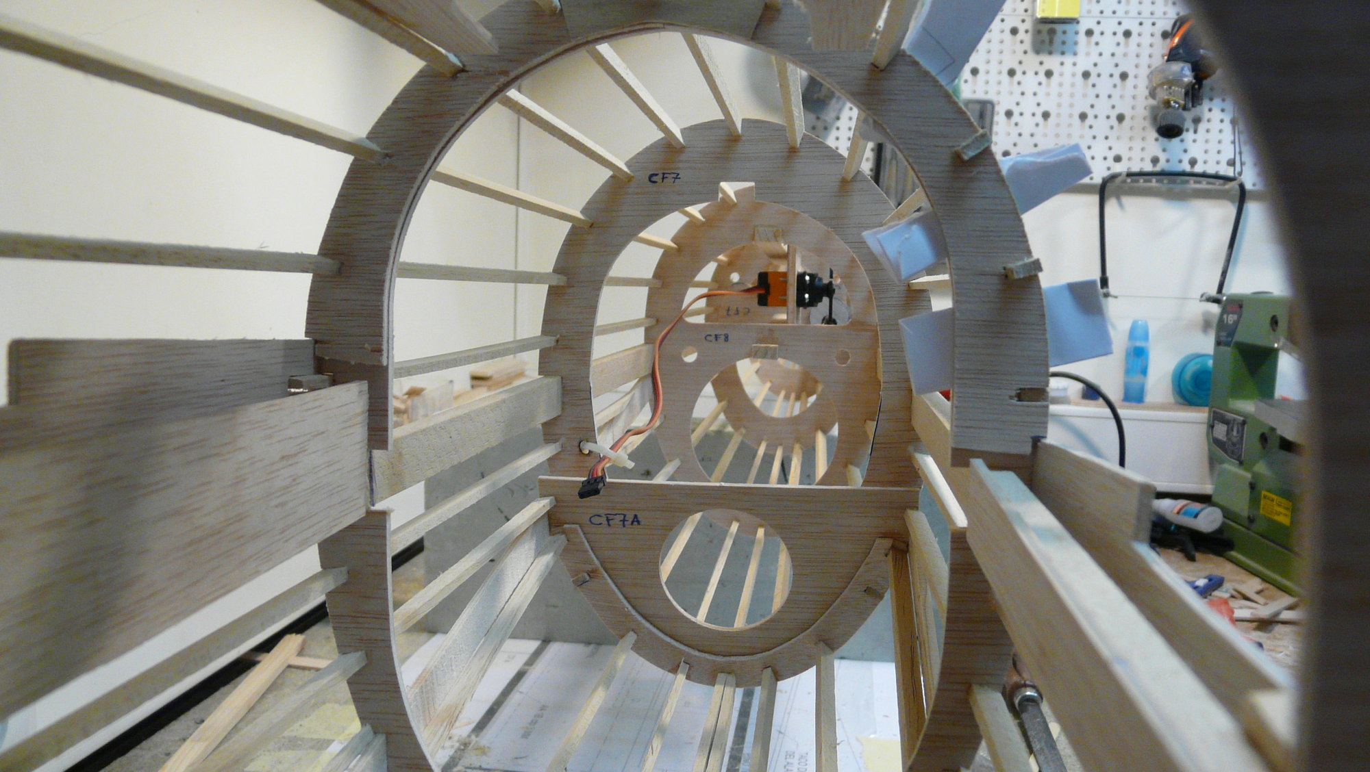
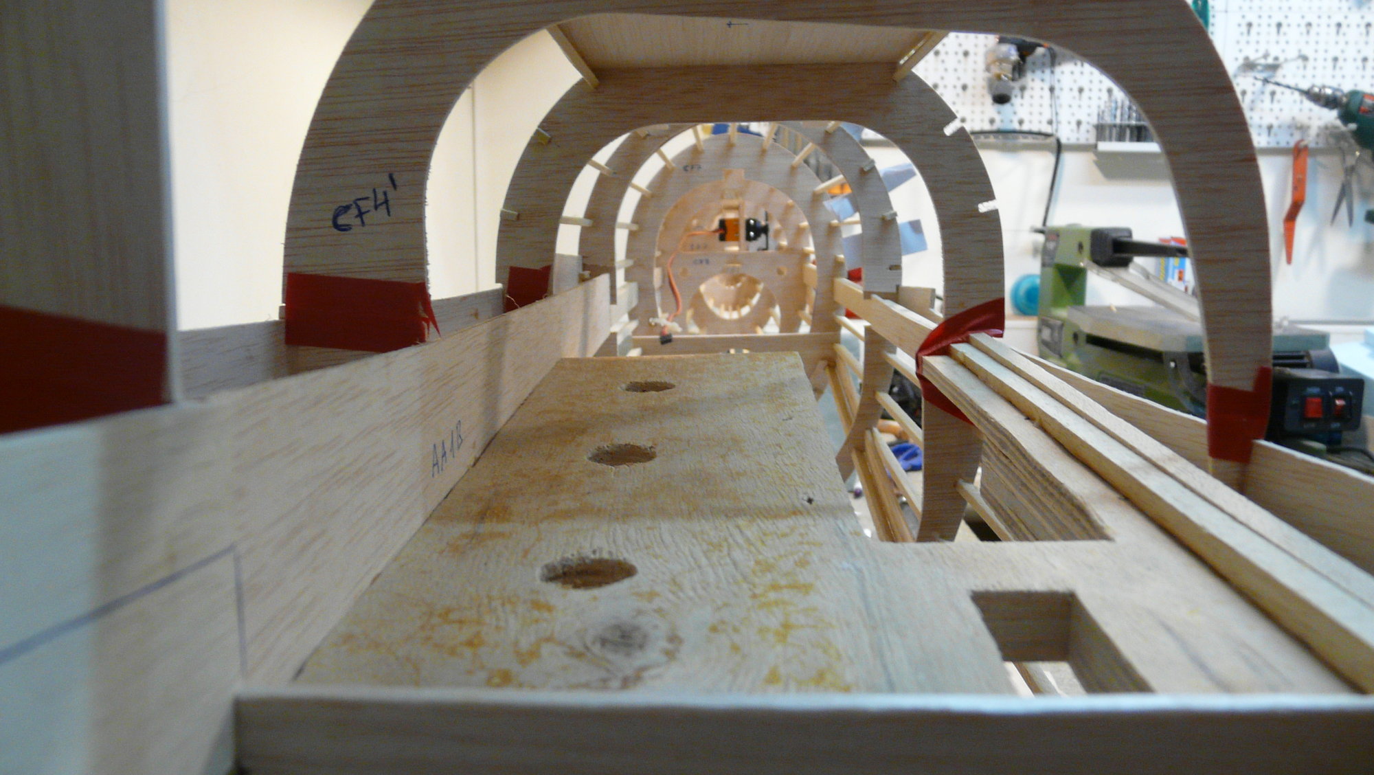
More details of the fuselage, seen from the inside. You will see some frames joined with adhesive tape, already pre-cut just where the seat of the central wing will pass
08-22-2018, 10:16 AM
#39
Thread Starter
Join Date: Oct 2012
Location: ZARAGOZA, SPAIN
Posts: 97
Likes: 0
Received 0 Likes
on
0 Posts
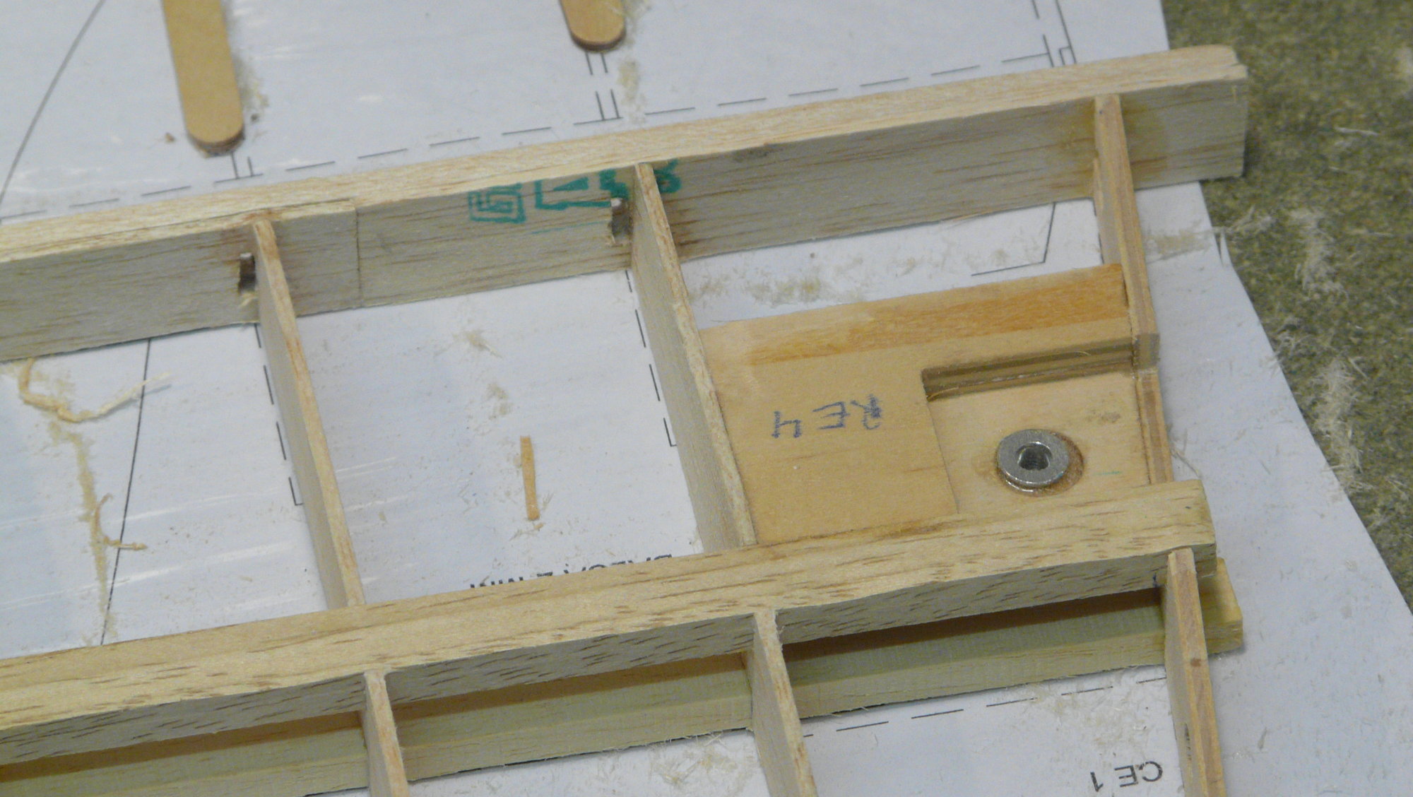
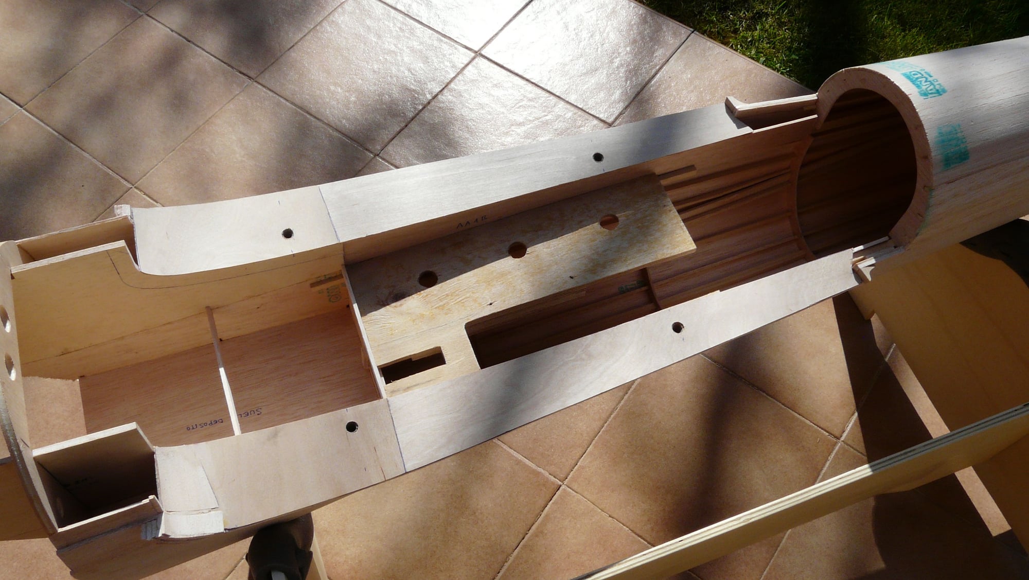
After the fuselages have been sheeted with 3 mm (1/8'') balsa wood using the same method used in the nacelle, the beechwood wing mounts blocks are glued in with slow epoxy, in which the central section of the wing is screwed and the beech dowels used to assemble the stabilizer are inserted. horizontal. In this way, the stabilizer surface remains with a positive incidence of 5 degrees respecting the horizontal of the fuselage mounting frame.
Finally, the hollow in the fuselage through which the central sections of the wing run is cut with a scalpel blade, helped with a profile template in that location. The upper and lower fillets are finished with the corresponding "kármán" of balsa transition and light putty.
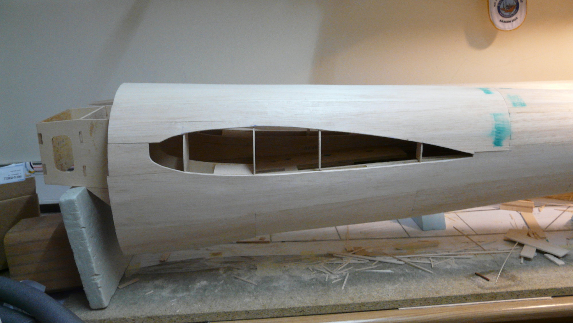
Wing mount blocks
Finally, the hollow in the fuselage through which the central sections of the wing run is cut with a scalpel blade, helped with a profile template in that location. The upper and lower fillets are finished with the corresponding "kármán" of balsa transition and light putty.
Wing mount blocks
08-26-2018, 07:04 AM
#41
Thread Starter
Join Date: Oct 2012
Location: ZARAGOZA, SPAIN
Posts: 97
Likes: 0
Received 0 Likes
on
0 Posts
Hi, Swordsn.
As I said at post #9, I decided to use a pair of two stroke single-cylinder, 9-hp each, because it is not convenient to exceed the power in this type of twin-engine. In-line motors can give overheating problems and the flat engines do not fit inside the cowl. Due to the type of construction and its lightness, I have been able to avoid using 100-120 cc engines (6.1-7.32 in3). I invite you to stay tuned for my next posts because I do not want to advance content to not alter the thread. Later I will comment on the brand and engine displacement.
As I said at post #9, I decided to use a pair of two stroke single-cylinder, 9-hp each, because it is not convenient to exceed the power in this type of twin-engine. In-line motors can give overheating problems and the flat engines do not fit inside the cowl. Due to the type of construction and its lightness, I have been able to avoid using 100-120 cc engines (6.1-7.32 in3). I invite you to stay tuned for my next posts because I do not want to advance content to not alter the thread. Later I will comment on the brand and engine displacement.
08-26-2018, 07:25 AM
#42
Thread Starter
Join Date: Oct 2012
Location: ZARAGOZA, SPAIN
Posts: 97
Likes: 0
Received 0 Likes
on
0 Posts
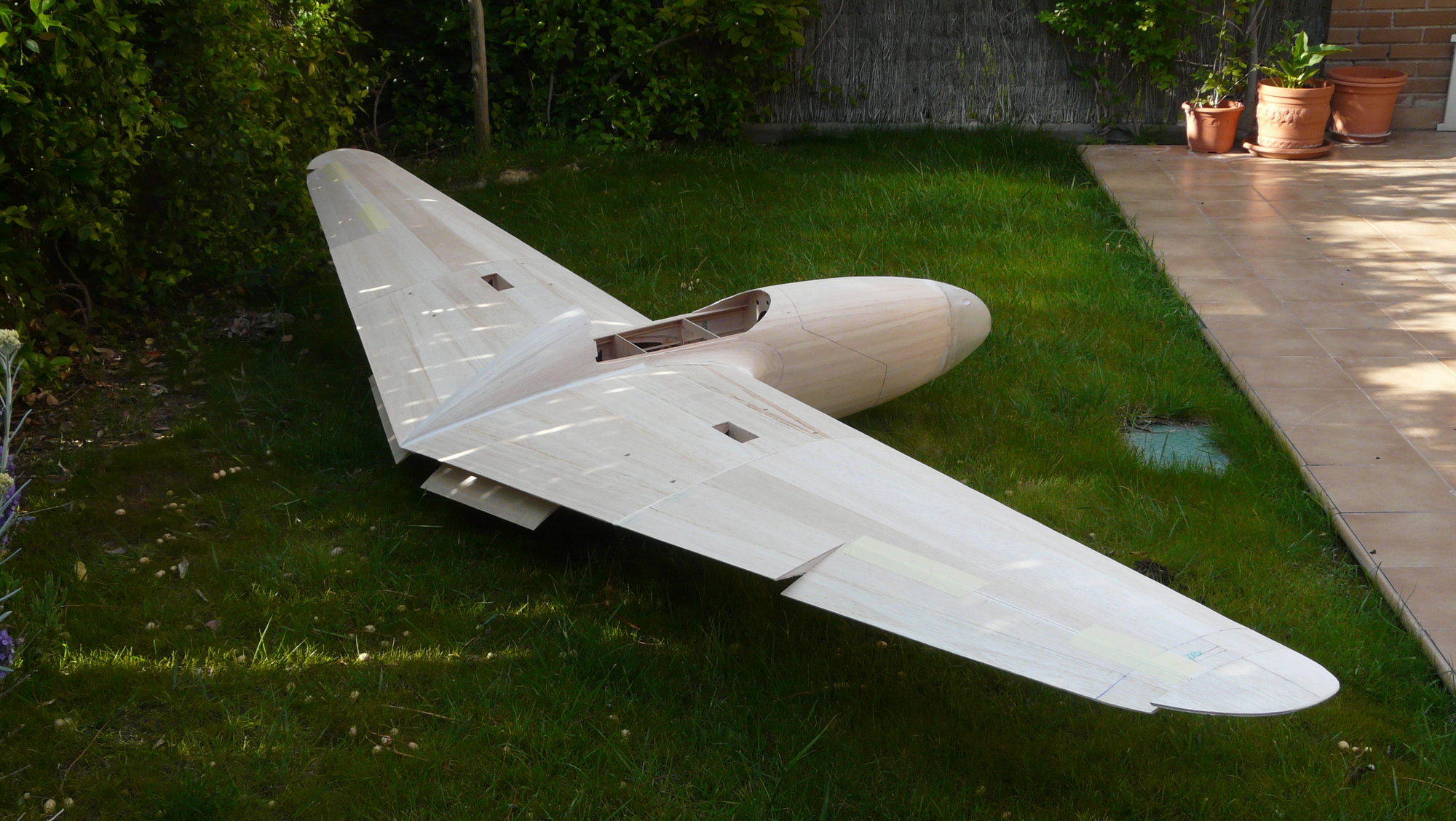
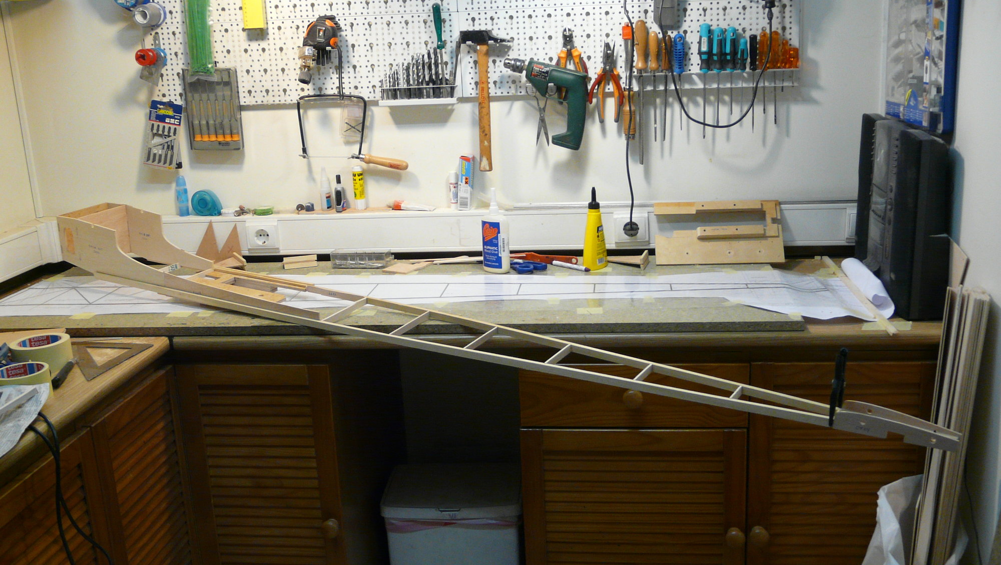
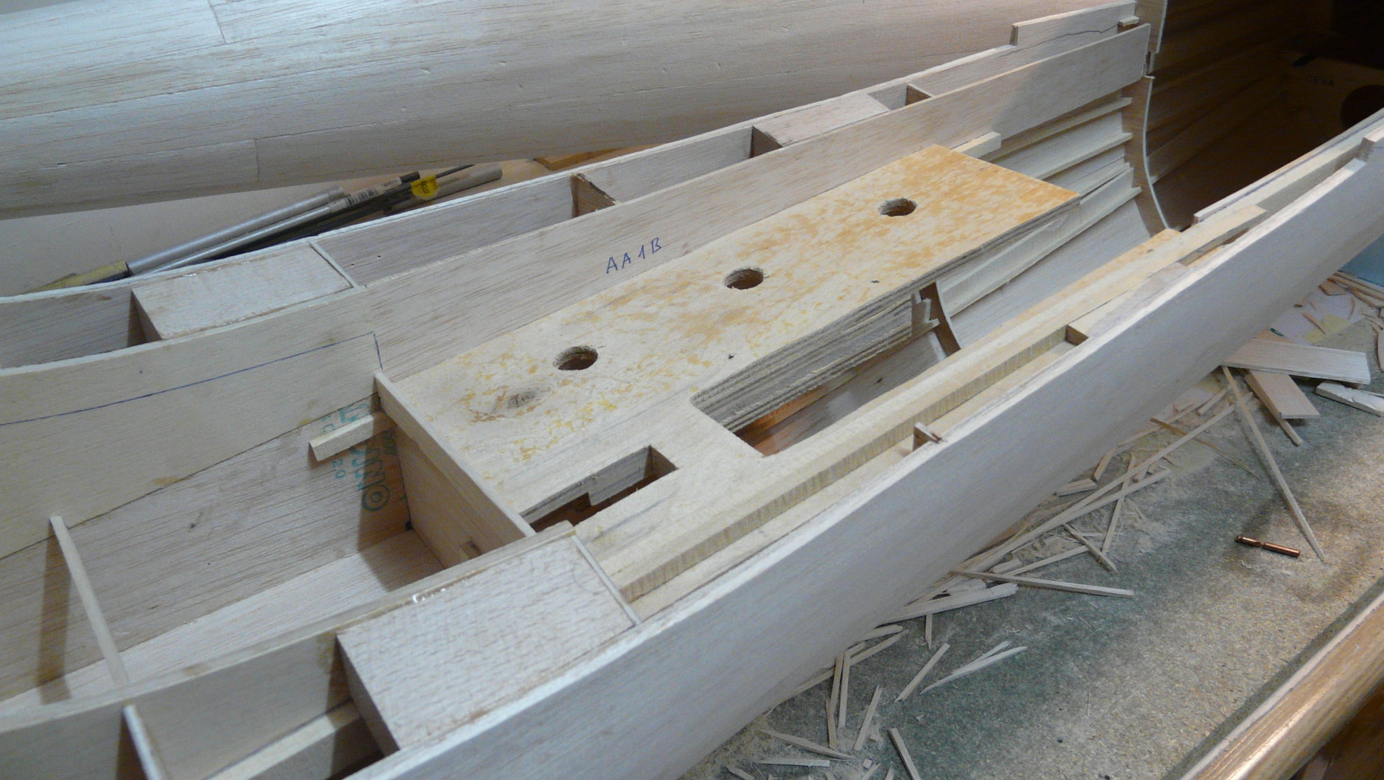
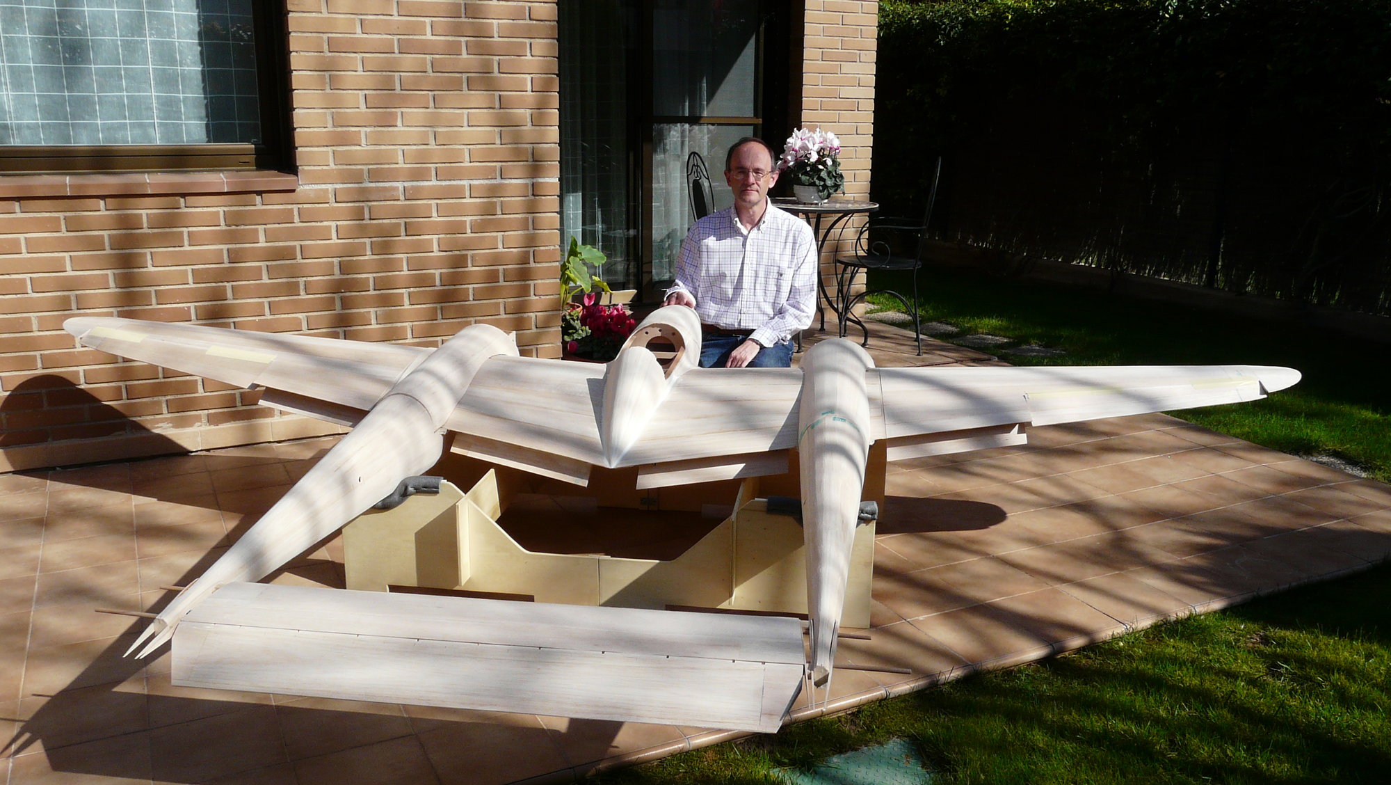
A critical moment of the construction takes place, without a doubt, when practicing the holes on the beech wing mounting blocks of the fuselages, since it is necessary to do it with all the modules built up to now (fuselages, section of nacelle-central wing, horizontal stabilizer and outer wings) perfectly assembled and aligned. Any failure will revert in a serious problem of geometry in the airplane. So, if we are not lucky enough to have a large enough workshop, it is time to storm the living room, with the necessary family permit and furniture clearance.
To do this, I built a folding bench in wood to rest the model on the fuselages, which, by the way, would be useful for mounting on the airfield. Said bench must place both fuselages equidistant from each other, parallel and horizontal, with the wing and horizontal stabilizer perfectly seated and square, so that the beech blocks of the section of the central wing coincide perfectly with those of the fuselage and the geometry of the airplane is the adequate You have to take your time to be sure of it.
Aligned set to drilling the mounting blocks
Wing tube
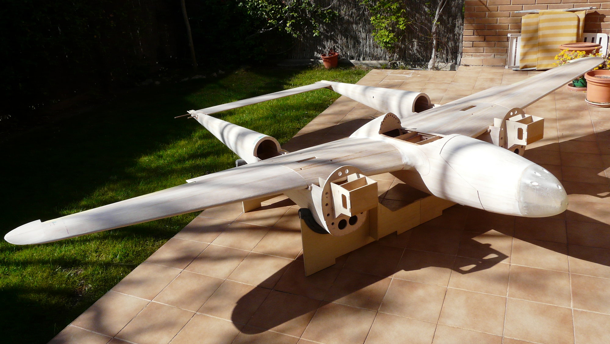
Outer wings must be in place before drilling to ensure the geometry
Through the holes already made in the wing, with a long drill of 6.5 mm the four blocks of each fuselage are marked slightly. It is convenient to remove the wing and check that the markings are correct. With the wing back in place, finish drilling them with the same drill. Once the wing has been removed, the holes are permanently tapped into M8 and the settlements of the heads of the eight M8 stainless steel screws in the wing blocks are countersunk. Apply several layers of cyano with intermediate threads to reinforce the thread in the fuselage blocks.
Result of the "surgical intervention"
To do this, I built a folding bench in wood to rest the model on the fuselages, which, by the way, would be useful for mounting on the airfield. Said bench must place both fuselages equidistant from each other, parallel and horizontal, with the wing and horizontal stabilizer perfectly seated and square, so that the beech blocks of the section of the central wing coincide perfectly with those of the fuselage and the geometry of the airplane is the adequate You have to take your time to be sure of it.
Aligned set to drilling the mounting blocks
Wing tube
Outer wings must be in place before drilling to ensure the geometry
Through the holes already made in the wing, with a long drill of 6.5 mm the four blocks of each fuselage are marked slightly. It is convenient to remove the wing and check that the markings are correct. With the wing back in place, finish drilling them with the same drill. Once the wing has been removed, the holes are permanently tapped into M8 and the settlements of the heads of the eight M8 stainless steel screws in the wing blocks are countersunk. Apply several layers of cyano with intermediate threads to reinforce the thread in the fuselage blocks.
Result of the "surgical intervention"
08-30-2018, 10:01 AM
#43
Thread Starter
Join Date: Oct 2012
Location: ZARAGOZA, SPAIN
Posts: 97
Likes: 0
Received 0 Likes
on
0 Posts
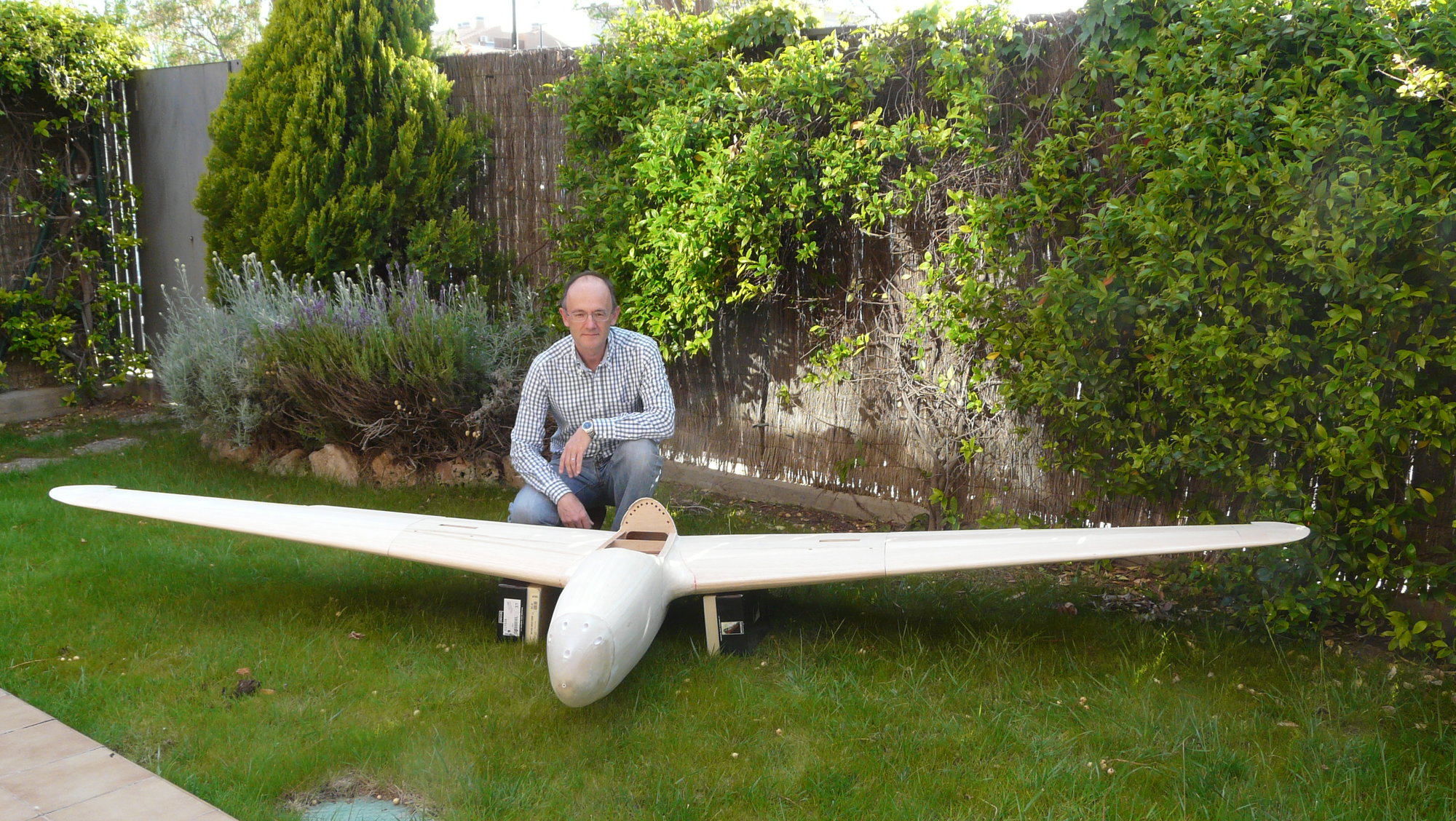
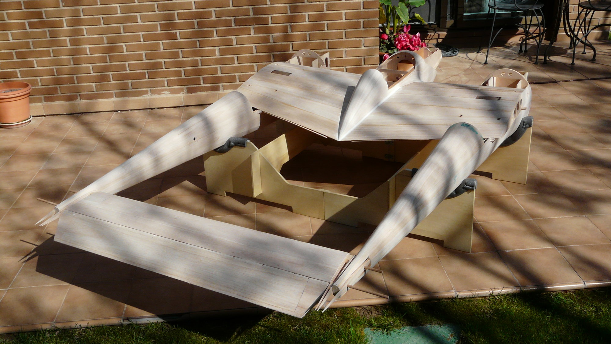
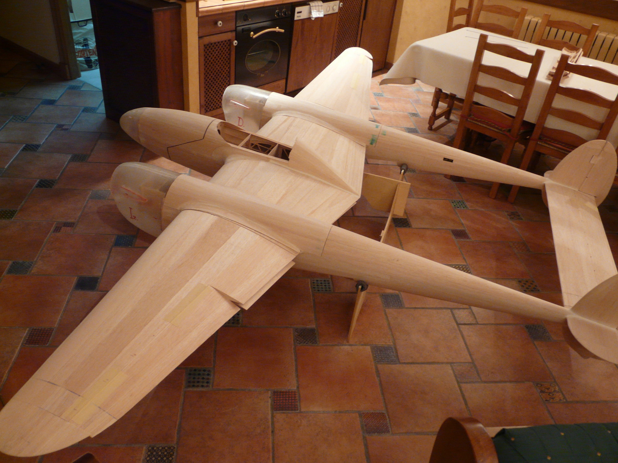
Some more pictures that I left "on the road", once the assembly's holes of all the modules were made. Sorry to be present in one, but I could not think of another way to give a real idea of its dimensions.
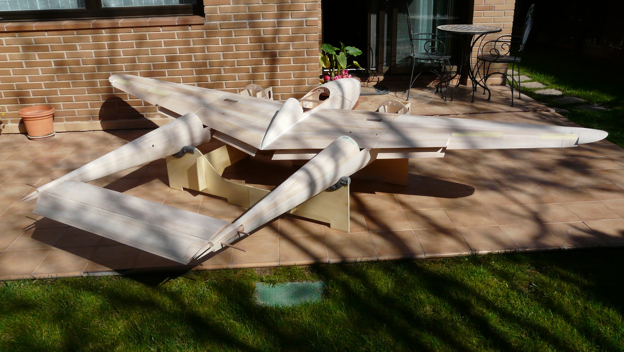
Assembly with full flaps
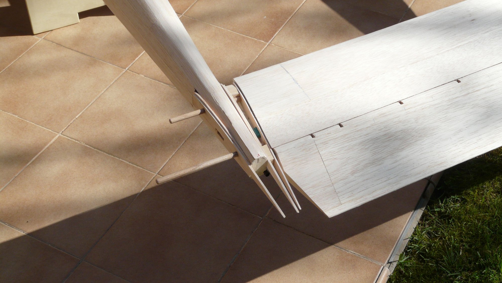
Stabilizer joint in detail. The outboard dowels are for mounting the stabilizer tips
Assembly with full flaps
Stabilizer joint in detail. The outboard dowels are for mounting the stabilizer tips
08-31-2018, 10:12 AM
#45
Thread Starter
Join Date: Oct 2012
Location: ZARAGOZA, SPAIN
Posts: 97
Likes: 0
Received 0 Likes
on
0 Posts
09-04-2018, 09:08 AM
#46
Thread Starter
Join Date: Oct 2012
Location: ZARAGOZA, SPAIN
Posts: 97
Likes: 0
Received 0 Likes
on
0 Posts
After a few days of rest and a few flights over the weekend, I continue with the completion of the structure of the fuselage.
Finally, the fins are built with the aircraft assembled to secure the square, based on balsa and samba stringers, 2 mm (3/32) balsa ribs, and 2 mm balsa sheeting. The rudders are hinged in the same way as the horizontal stabilizer, so they are also removable
.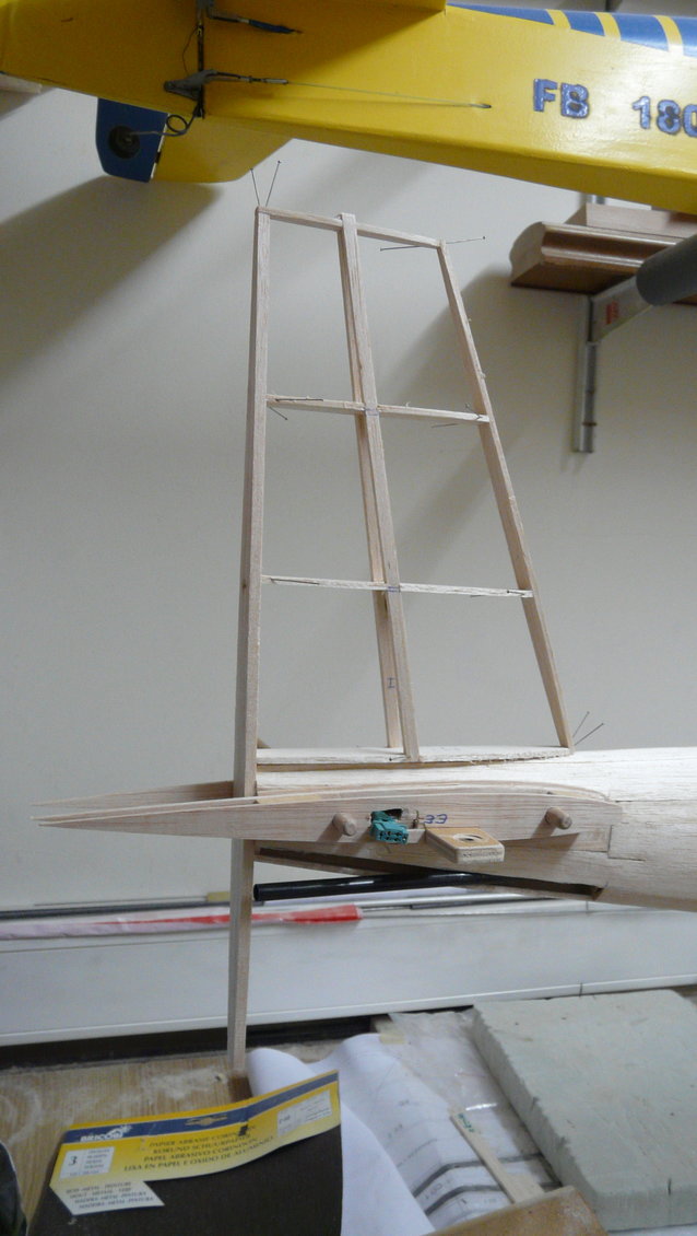
Fin structure
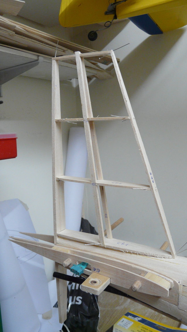
MPX connector for both stabilizer servos and rudder control rod
Sheeting the fin
Semi-ribs for the stabilizer tip
Finally, the fins are built with the aircraft assembled to secure the square, based on balsa and samba stringers, 2 mm (3/32) balsa ribs, and 2 mm balsa sheeting. The rudders are hinged in the same way as the horizontal stabilizer, so they are also removable
.
Fin structure
MPX connector for both stabilizer servos and rudder control rod
Sheeting the fin
Semi-ribs for the stabilizer tip
09-10-2018, 08:28 AM
#47
Thread Starter
Join Date: Oct 2012
Location: ZARAGOZA, SPAIN
Posts: 97
Likes: 0
Received 0 Likes
on
0 Posts
Finally, after a perfect sanding to round the joints of the sheeting staves, the landing doors are manufactured in fiberglass reinforced with carbon strips, in the same way that I described on the occasion of the nacelle landing door.
Since both fuselages are identical in this area, fortunately it is only necessary to obtain a mold. Finally, the hollows of the doors in the fuselage are cut with a scalpel blade and the pieces obtained in fiber are adapted, which are hinged, in my case, with hinges made with fiber printed circuit. Do not forget to make the double interior balsa wall.
I regret not having photographs of the landing doors in this phase, although you will see them in later descriptions.
09-27-2018, 08:41 AM
#48
Thread Starter
Join Date: Oct 2012
Location: ZARAGOZA, SPAIN
Posts: 97
Likes: 0
Received 0 Likes
on
0 Posts
Cowls, fairings, canopy and other items
The P-38 Lightning is a multi-cowl aircraft, with many air-scoops, grilles and trap doors that complicate the task. If we add to that the aggravation of the scale, we will see that the work is arduous and endless.
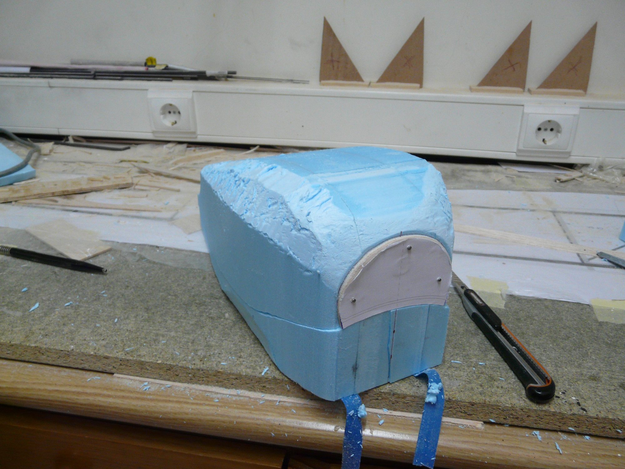
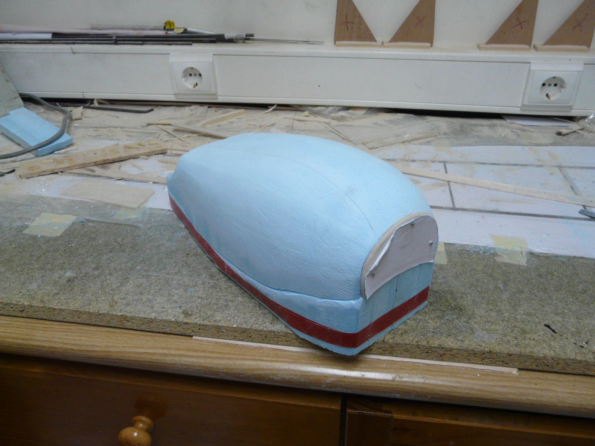
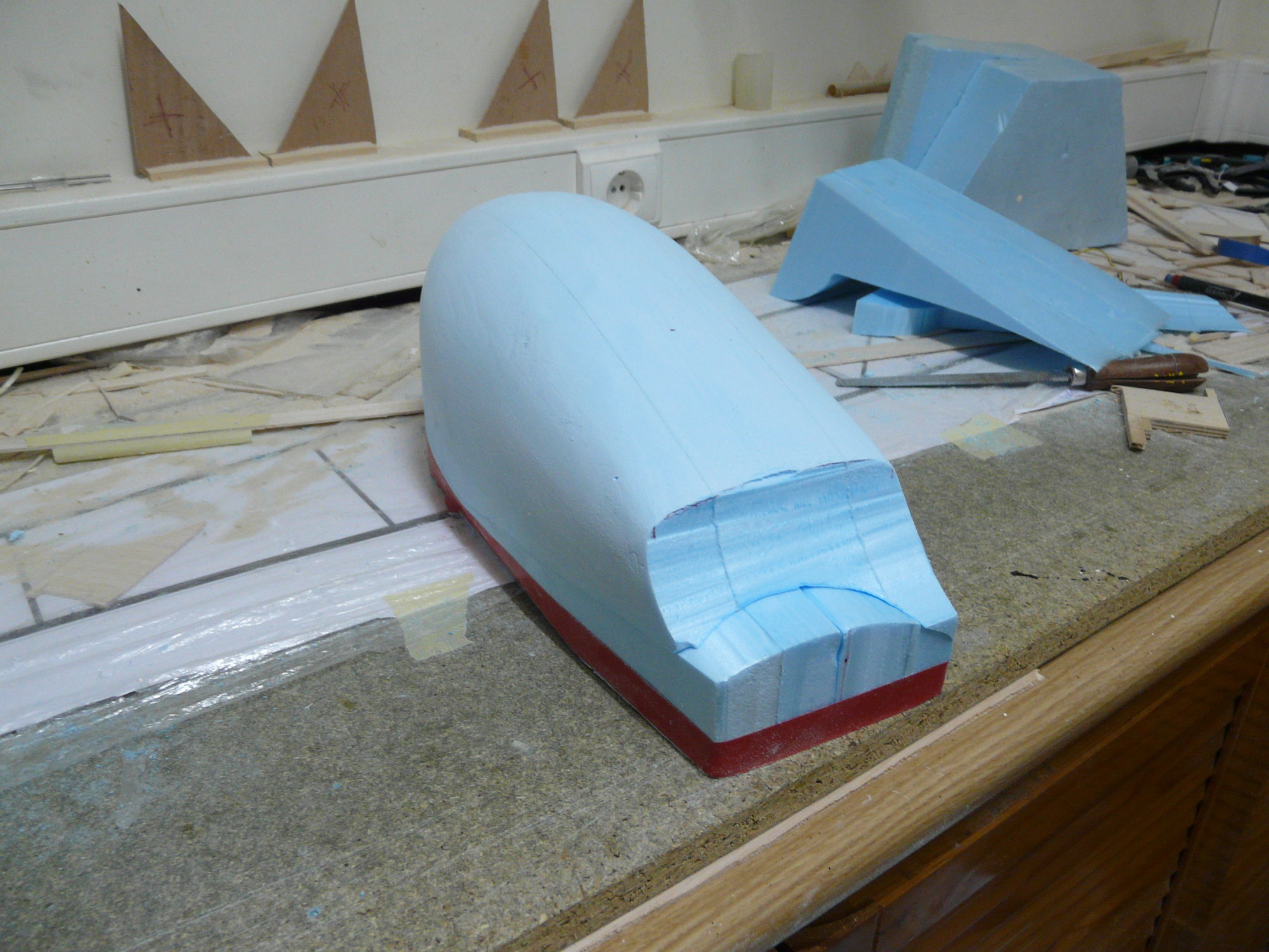
All have been manufactured in fiberglass and epoxy resin with recoverable mold, even at the cost of more work. Nothing to add to the technique used, which is the usual in these arts, with bivalve molds in most cases. In most cases, Styrofoam® (Blue board) has been used as the plug to be carved; in others, soft wood.
We must bear in mind that, except for the nose of the gondola, everything is double, so with a mold we can make the two symmetrical pieces in the fuselages; however, the bulky fairings of both engines are different, since, when turning in the same direction, the frontal incidence of the right is different from the left.
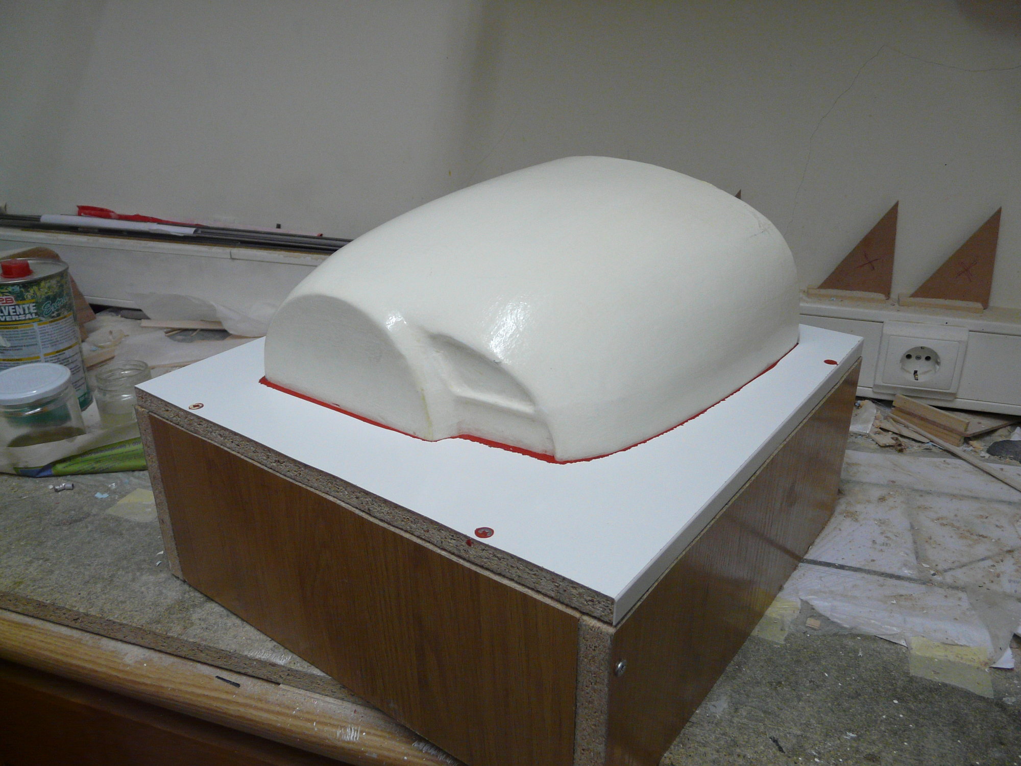
I do not know about the meters of fiberglass and resin that it carries, although I have tried to make all the pieces as light as possible.
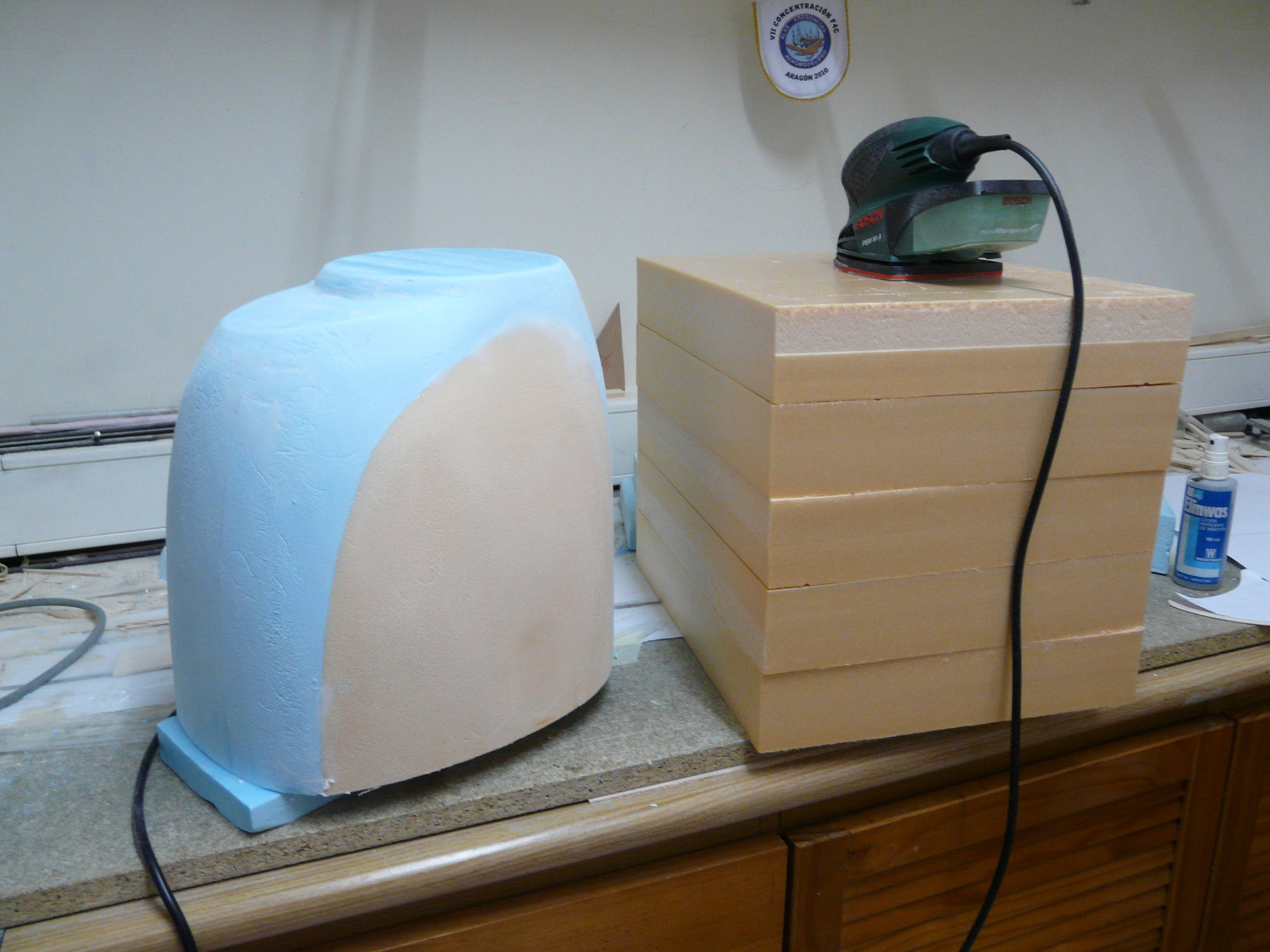
The plug of the engine cowl, ready to be primed
Before laying fiber and epoxy
Cowling almost finished
The P-38 Lightning is a multi-cowl aircraft, with many air-scoops, grilles and trap doors that complicate the task. If we add to that the aggravation of the scale, we will see that the work is arduous and endless.
All have been manufactured in fiberglass and epoxy resin with recoverable mold, even at the cost of more work. Nothing to add to the technique used, which is the usual in these arts, with bivalve molds in most cases. In most cases, Styrofoam® (Blue board) has been used as the plug to be carved; in others, soft wood.
We must bear in mind that, except for the nose of the gondola, everything is double, so with a mold we can make the two symmetrical pieces in the fuselages; however, the bulky fairings of both engines are different, since, when turning in the same direction, the frontal incidence of the right is different from the left.
I do not know about the meters of fiberglass and resin that it carries, although I have tried to make all the pieces as light as possible.
The plug of the engine cowl, ready to be primed
Before laying fiber and epoxy
Cowling almost finished
09-27-2018, 09:02 AM
#49
Thread Starter
Join Date: Oct 2012
Location: ZARAGOZA, SPAIN
Posts: 97
Likes: 0
Received 0 Likes
on
0 Posts
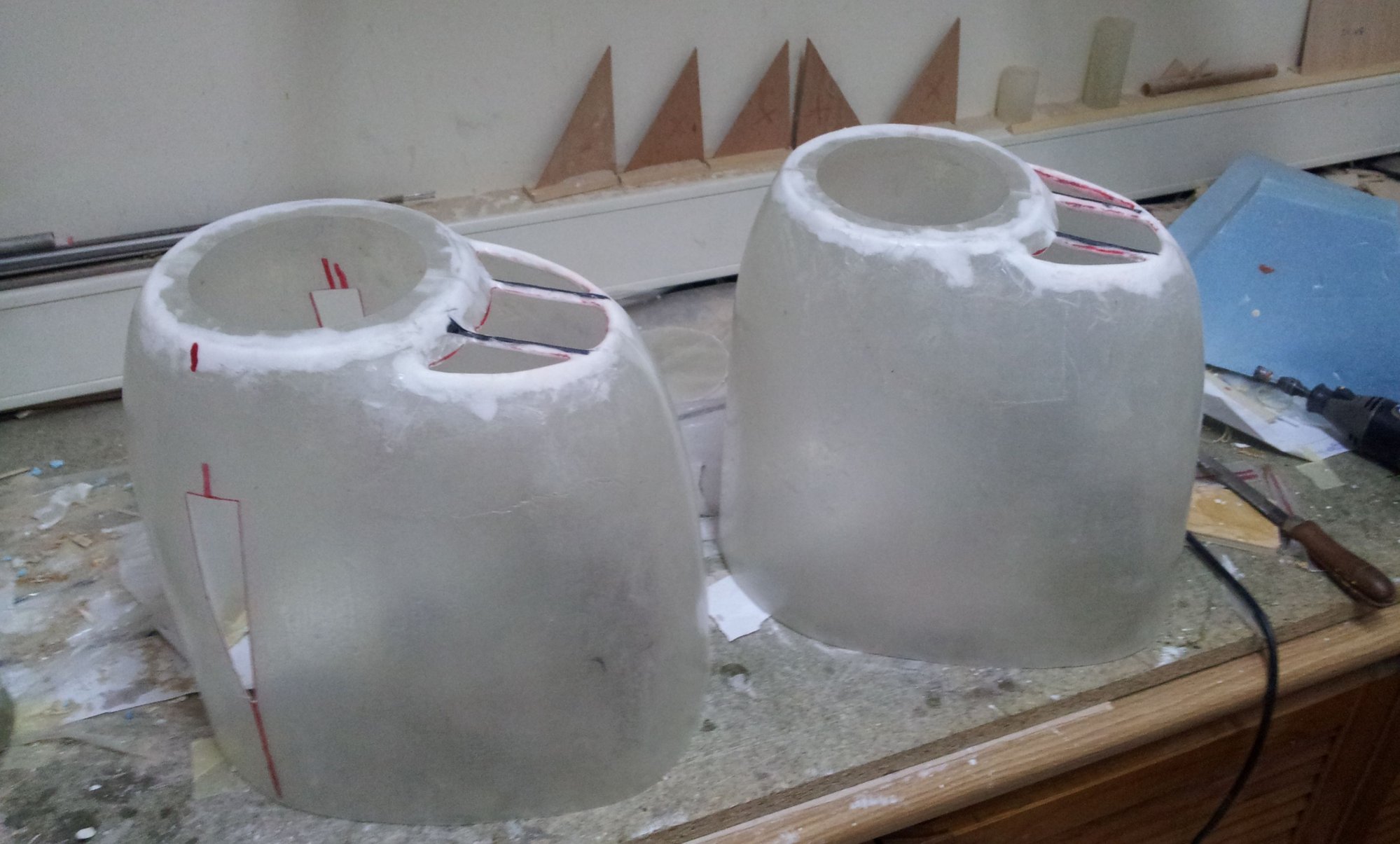
In the same way as the landing gear doors, the fairings of the turbochargers have been obtained from the mold on the fuselage.
The molds of the prominent side radiators of the fuselages, however, have required two solid plugs carved in Styrofoam® (Blue board) that must previously fit perfectly on their settlement.
Carving the radiator fairing
The prop spinners have been manufactured with mold in hard wood carved by CNC
The nose of the gondola and the different nozzles are easier to make, although its location on some of the fairings takes time
Superchargers air-scoops
10-06-2018, 07:02 AM
#50
Thread Starter
Join Date: Oct 2012
Location: ZARAGOZA, SPAIN
Posts: 97
Likes: 0
Received 0 Likes
on
0 Posts
Now it is time to go placing the different fairings to check their fit. The different scoops and inlet grids are made with new partial molds.
Observe access to the rudder servo that is hidden by the inner radiator fairing
Observe access to the rudder servo that is hidden by the inner radiator fairing

